
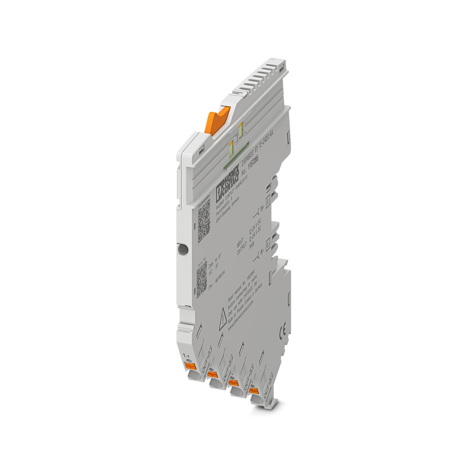
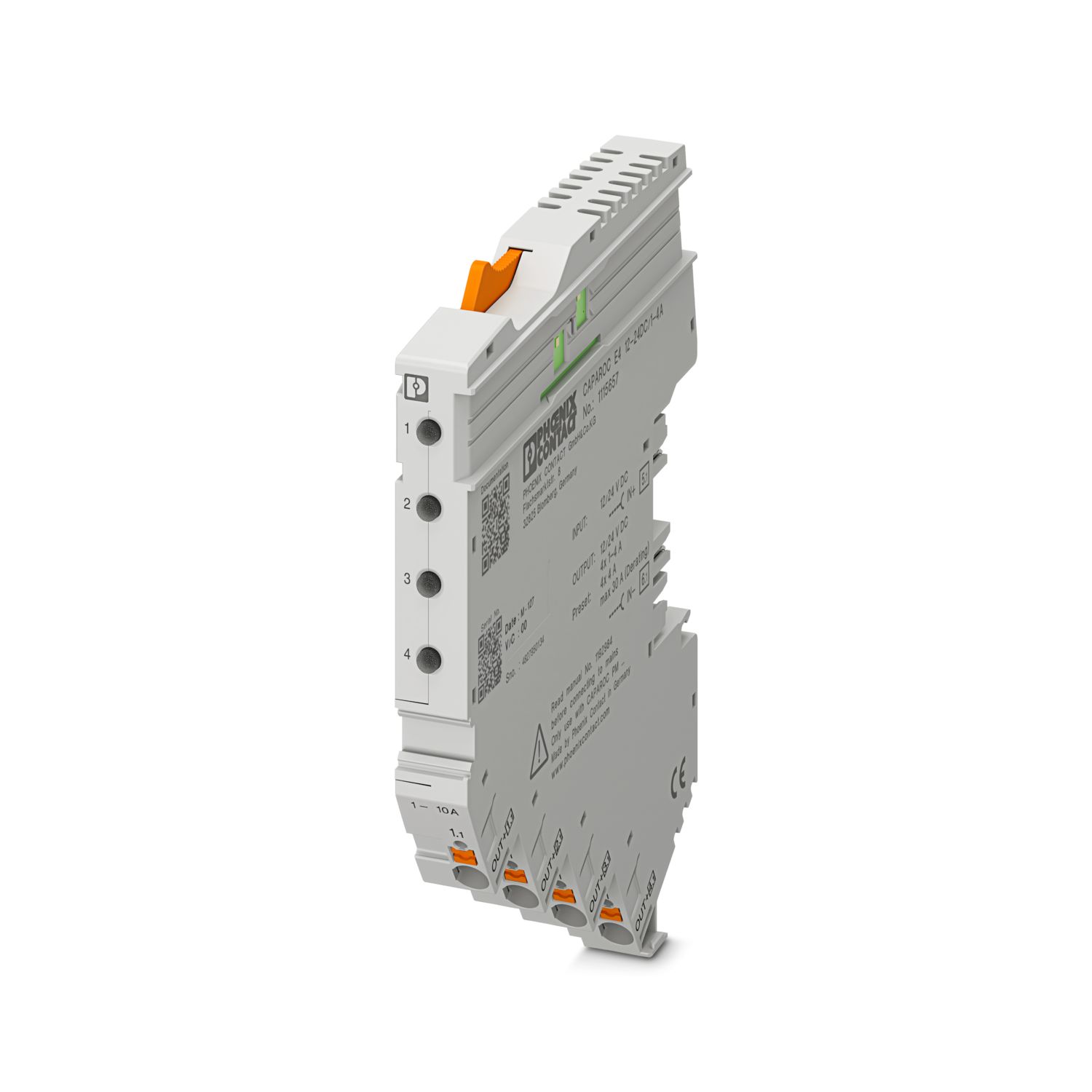
CAPAROC PM S-R
-
電源モジュール
1115661
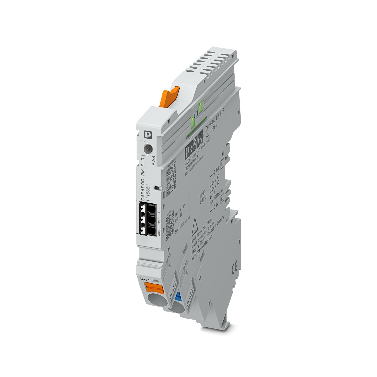

CAPAROCサーキットブレーカシステムに12または24 V DCを供給するための状態出力とリセット入力を備えた電源モジュール。CAPAROCカレントレールを介したDINレール設置用
この製品を操作するには追加の製品が必要となります。
必須アクセサリ
製品の詳細
| 概要 | |
| 注記 | LABSリリース―テスト仕様VW PV 3.10.7:2005-0に準拠 |
| 電線を接続する際は、CAPAROCモジュールが引張力によって引き離されていないことを確認してください。モジュール間にギャップを作らないようにしてください。 | |
| 製品の種類 | 機器用ミニチュアサーキットブレーカ |
| 製品シリーズ | CAPAROC |
| タイプ | プラグインモジュール |
| スロット数 | 2 |
| 絶縁特性 | |
| 保護クラス | III |
| 汚染度 | 2 |
| 概要 | |
| 定各電圧 | 10 V DC ... 30 V DC |
| 定格電圧 | 12 V DC |
| 24 V DC | |
| 定格電流IN | 45 A (総電流入力) |
| 定格サージ電圧 | 0.5 kV |
| 引き外し方式 | E(電子仕様) |
| 耐電圧 | 35 V DC (負荷回路) |
| 効率 | > 99 % |
| 閉回路電流I0 | 通常 9 mA (無負荷、24 V時) |
| 電力損失 | 通常 0.22 W (無負荷、24 V時) |
| < 1.5 W (24 Vおよび45 Aでの公称動作時) | |
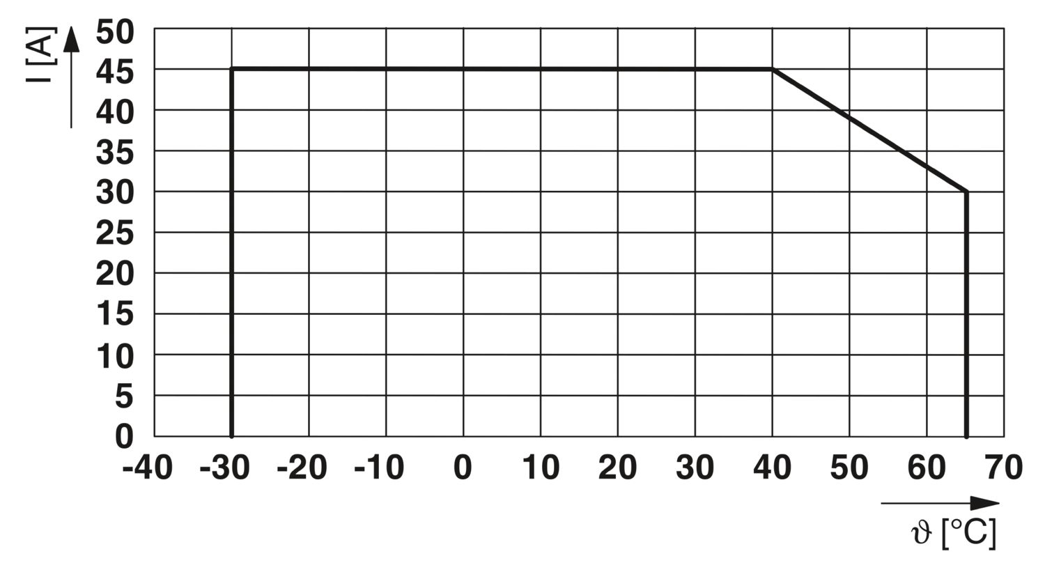
| 温度ディレーティング | 45 A (40°C時の総電流) |
| 30 A (65 °C時の総電流) | |
| MTBF (IEC 61709, SN 29500) | 18886912.65 h (負荷21%で25°C時) |
| 5907048.64 h (負荷34.25 %で40 °C時) | |
| 933563.97 h (負荷 100%で40°C 時) | |
| 電圧降下 | 0.03 V (45 A時) |
| 負荷回路 | |
| 不足電圧スイッチオフ | ≤ 9.2 V DC (アクティブ) |
| ≥ 10.2 V DC (非アクティブ) | |
| 過電圧スイッチオフ | ≥ 30.5 V DC (アクティブ) |
| ≤ 29.5 V DC (非アクティブ) | |
| リセット | |
| 入力電圧範囲 | 7 V DC ... 30 V DC (立下りエッジでリセット) |
| 消費電流 | 通常 0.5 mA (約 24 V DC) |
| パルス長 | ≥ 50 ms |
| 剥き線長さ | 8 mm |
| 接続電線サイズ、単線 | 0.2 mm² ... 1.5 mm² |
| 接続電線断面積AWG | 24 ... 16 |
| 撚線接続断面積、フェルールあり、プラスチックスリーブあり | 0.2 mm² ... 0.75 mm² |
| 接続電線断面積/撚線、棒端子あり、プラスチックスリーブなし | 0.2 mm² ... 1.5 mm² |
| 状態出力 | |
| 出力電圧 | 最大 30 V DC (入力電圧±5%(エラーなしの場合)) |
| 0 V DC (エラー) | |
| 出力定格電流 | 最大 20 mA |
| 剥き線長さ | 8 mm |
| 接続電線サイズ、単線 | 0.2 mm² ... 1.5 mm² |
| 接続電線断面積AWG | 24 ... 16 |
| 撚線接続断面積、フェルールあり、プラスチックスリーブあり | 0.2 mm² ... 0.75 mm² |
| 接続電線断面積/撚線、棒端子あり、プラスチックスリーブなし | 0.2 mm² ... 1.5 mm² |
| 状態出力 | |
| 出力電圧 | 最大 30 V DC (少なくとも1チャネルでI >80%の場合、入力電圧±5%) |
| 出力定格電流 | 最大 20 mA |
| 剥き線長さ | 8 mm |
| 接続電線サイズ、単線 | 0.2 mm² ... 1.5 mm² |
| 接続電線断面積AWG | 24 ... 16 |
| 撚線接続断面積、フェルールあり、プラスチックスリーブあり | 0.2 mm² ... 0.75 mm² |
| 接続電線断面積/撚線、棒端子あり、プラスチックスリーブなし | 0.2 mm² ... 1.5 mm² |
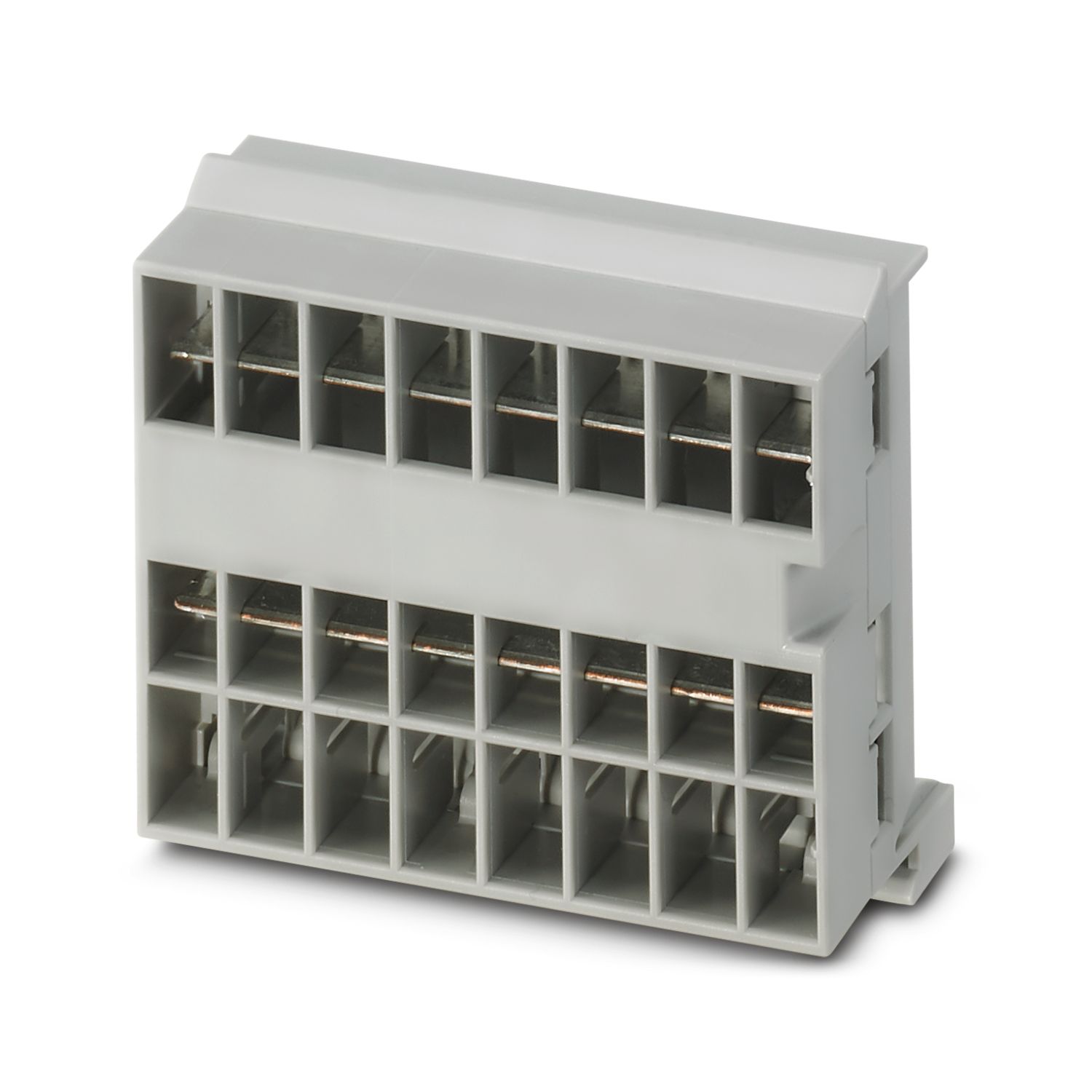
| 主回路IN+ | |
| 接続方法 | プッシュイン式 |
| 剥き線長さ | 18 mm |
| 接続電線サイズ、単線 | 0.5 mm² ... 16 mm² |
| 接続電線断面積AWG | 20 ... 8 |
| 撚線接続断面積、フェルールあり、プラスチックスリーブあり | 0.5 mm² ... 16 mm² |
| 接続電線断面積/撚線、棒端子あり、プラスチックスリーブなし | 0.5 mm² ... 16 mm² |
| 主回路IN- | |
| 接続方法 | プッシュイン式 |
| 剥き線長さ | 18 mm |
| 接続電線サイズ、単線 | 0.5 mm² ... 16 mm² |
| 接続電線断面積AWG | 20 ... 8 |
| 撚線接続断面積、フェルールあり、プラスチックスリーブあり | 0.5 mm² ... 16 mm² |
| 接続電線断面積/撚線、棒端子あり、プラスチックスリーブなし | 0.5 mm² ... 16 mm² |
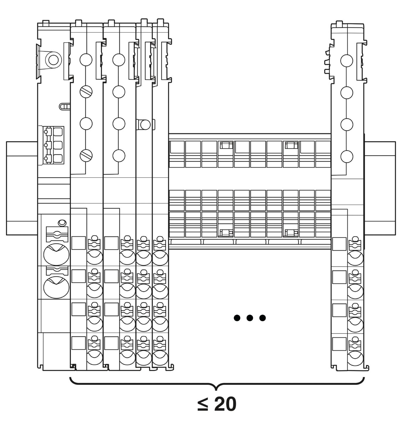
| 最大限のシステム拡張 | ≤ 20 (CAPAROCモジュールは配列可能です) |
| 電源(PWR)LED緑 | 点灯 (チャネルエラーなし) |
| 点灯 (電源電圧(定格範囲)) | |
| 点滅 (3倍(プログラミングロック解除時)) | |
| 電源(PWR)LED赤 | 点灯 (電源電圧(定格範囲外)) |
| 電源(PWR)LED黄 | 点滅 (3倍(プログラミングロック作動時)) |
| 信号LED緑 | 点灯 (チャネルエラーなし) |
| 点灯 (電源電圧(定格範囲)) | |
| 信号LED黄 | 点灯 (少なくとも1チャネルでI > 80%時) |
| 信号LED赤 | 点灯 (少なくとも1つのチャンネルエラーあり) |
| 点灯 (電源電圧(定格範囲外)) |
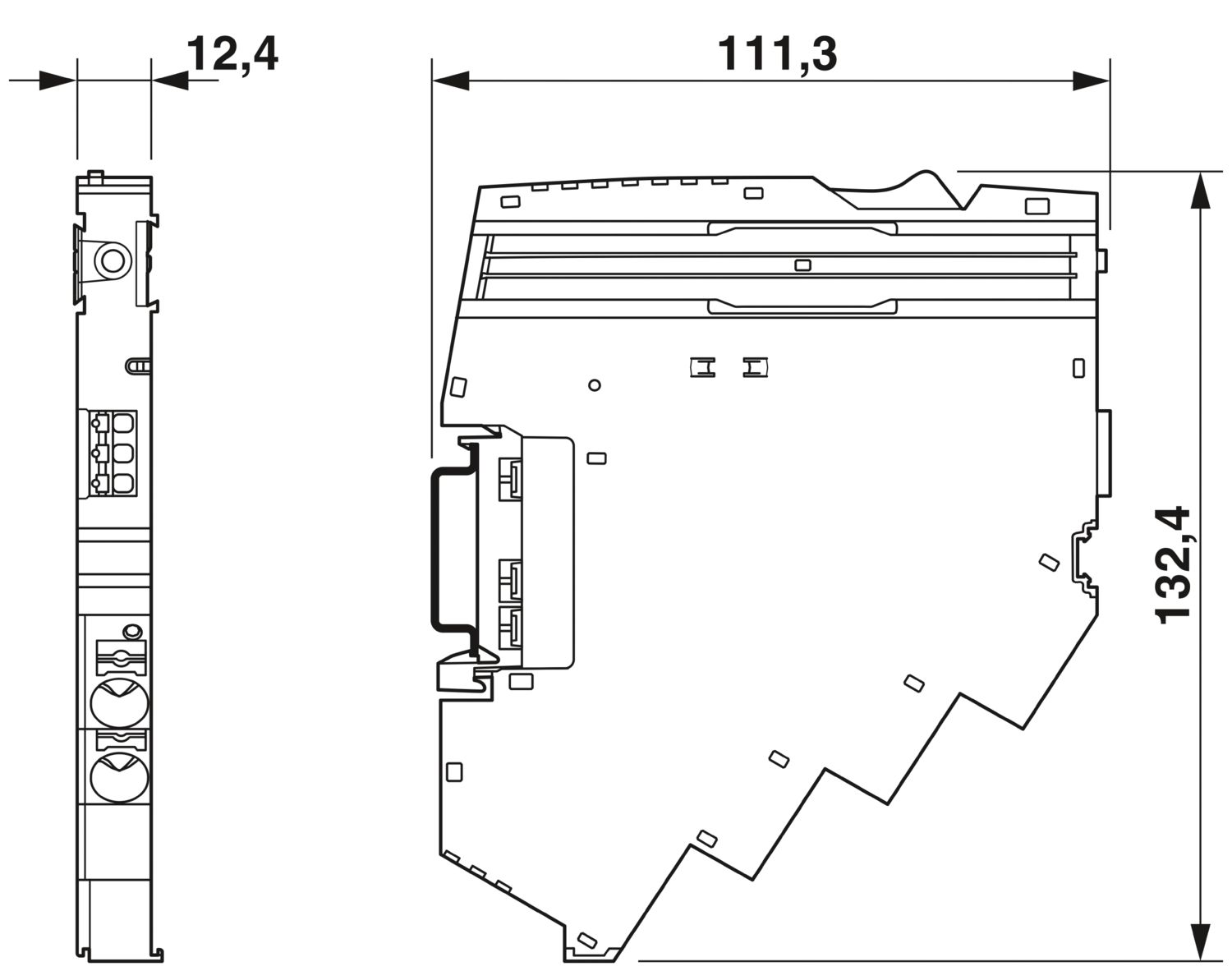
| 外形寸法 |
|
| 幅 | 12.4 mm |
| 高さ | 132.4 mm |
| 奥行き | 111.3 mm (DINレール 7.5 mmを含む) |
| 色 | ライトグレー (RAL 7035) |
| 部材 | PA 6 |
| PA 6 | |
| PA 6 | |
| PC | |
| UL94難燃性クラス | V-0 |
| 周囲条件 | |
| 保護等級 | IP20 |
| 使用周囲温度 | -30 °C ... 65 °C |
| 周囲温度(保管時/運搬時) | -40 °C ... 70 °C |
| 高度 | ≤ 4000 m (amsl) |
| 湿度試験 | 96時間、相対湿度95 %、40 °C |
| 衝撃(動作時) | 30g (11 ms間隔、半正弦衝撃波、IEC 60068-2-27に準拠) |
| 25g (6 msの継続時間、IEC 60068-2-27準拠の正弦半波の衝撃パルス、連続衝撃) | |
| 振動(動作時) | 5g (10 Hz ... 150 Hz / 10サイクル / 軸 / X、Y、Z) |
| UL認証 | |
| 表示記号 | UL/C-UL Listed UL 508 |
| UL 121201 Class I, Division 2, Groups A, B, C, D, T4A | |
| 腐食性ガス試験 | |
| 表示記号 | ISA S71.04.2013 G3 Harsh Group A |
| 標準/仕様 | EN 61000-6-2 |
| 注記 | EMC―工業地域向けのイミュニティ |
| 標準/仕様 | EN 61000-6-3 |
| 注記 | EMC―居住用、企業用、商業用不動産および小規模事業のエミッション |
| 標準/仕様 | EN 60068-2-78 |
| 注記 | 環境への影響―湿度と熱、一定 |
| 標準/仕様 | EN 50178 |
| 注記 | 電源設備に電子機器を装備 |
| 標準/仕様 | EN 60068-2-6 |
| 注記 | 環境への影響―振動(正弦波) |
| 標準/仕様 | EN 60068-2-27 |
| 注記 | 環境への影響―衝撃 |
| 取付けタイプ | CAPAROC CR…カレントレールにプラグ着脱可能 |


特長
単一の信号を選択してカスタマイズできるベンチマークとPROFINET通信までのリセット
工具不要の組立て、バスバーへの直接送電、明確な動作状態により、どなたでも操作が非常に簡単
包括的なデジタルデータパケットとPROFINETファンクションブロックにより、非常に簡単なデザインイン

よくある質問
CAPAROC PM S-R電源モジュールはどのような信号を供給しますか。
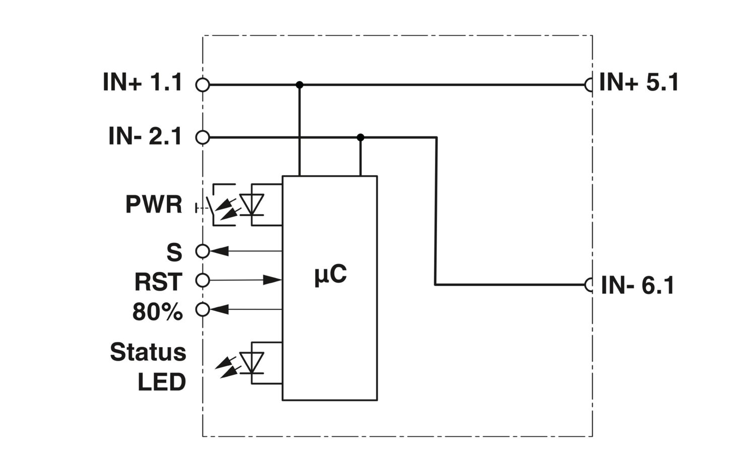
モジュールには、信号用に3種類の接続オプションがあります:
S - ステータス出力:電位基準付きの集約信号で、システムの状態を示します。故障停止が1件でも発生すると、メッセージが出力されます。
High (24 V) = 異常なし
Low (0 V) = 少なくとも1件の故障停止あり
最大電流20 mA
RST - リセット入力:エラーによってオフになったチャンネルは、立ち下がりエッジによって再びオンになります。
I > 8...
もっと見る
モジュールには、信号用に3種類の接続オプションがあります:
S - ステータス出力:電位基準付きの集約信号で、システムの状態を示します。故障停止が1件でも発生すると、メッセージが出力されます。
High (24 V) = 異常なし
Low (0 V) = 少なくとも1件の故障停止あり
最大電流20 mA
RST - リセット入力:エラーによってオフになったチャンネルは、立ち下がりエッジによって再びオンになります。
I > 80%信号出力:電位基準付きの集約信号。チャンネルに流れる電流が設定された定格電流の80%を超えると、HIGH信号(24 V)が出力されます。
CAPAROCの機能が説明されているハードウェアの紹介動画はありますか。
インフィードモジュールの下流には、サーキットブレーカモジュールを何台接続できますか。
CAPAROC PM S-R:サーキットブレーカモジュールx 20
CAPAROC PM IOL:20チャンネル
CAPAROC PM PN:サーキットブレーカモジュールx 16
CAPAROC PM EIP:サーキットブレーカモジュールx 16
CAPAROC PM MB:サーキットブレーカモジュールx 16
CAPAROC PM EC:サーキットブレーカモジュールx 16
チャンネルLEDは、4秒ごとに2回黄色に点滅します。 これは何を意味するのでしょうか。
これは、電源モジュールとの内部通信が遮断されているか、または故障していることを意味します。
モジュールが正しく取り付けられ、モジュール間に隙間がないことを確認してください。それでも通信が切断される場合は、点滅している最初のモジュール(左)の側面接点を確認してください。接点が曲がっている、モジュールの中に入り込みすぎている、ハウジング開口部の中心からずれている、またはその他の損傷がある場合は、モジュールを交換してください。
設定電流の設定をブロックできますか。
電流はさまざまな方法でロックすることができます:
1.プログラミングロック:電源モジュールのPWRボタンを3秒以上押すと、PWR LEDが黄色に3回点滅し、設定がロックされます。 もう一度3秒以上押すと、LEDが緑色に3回点滅し、再びロックが解除されます。
2.ロックは通信インターフェース経由でも設定や解除ができます。操作ロックもここで設定でき、これにより機器の操作や設定ができなくなります。その後、ロックはインターフェイス経由でのみ解除できます。