cUL認証済み
認証ID: E118976-20230317| 定格電圧UN | 定格電流IN | 適合線サイズAWG | 適合線サイズ mm2 | |
|---|---|---|---|---|
| keine | ||||
| 29.9 V | 1.4 A | |||
UL 認証
認証ID: E118976-20230317| 定格電圧UN | 定格電流IN | 適合線サイズAWG | 適合線サイズ mm2 | |
|---|---|---|---|---|
| keine | ||||
| 29.9 V | 2 A | |||

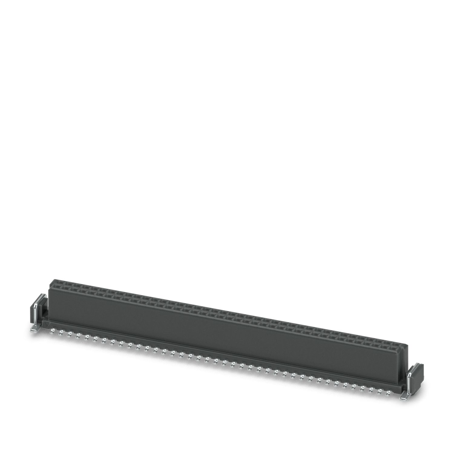
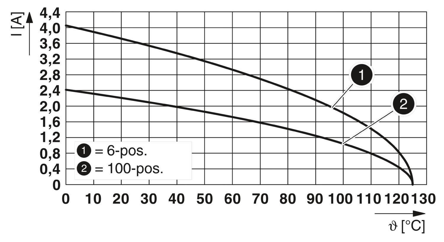
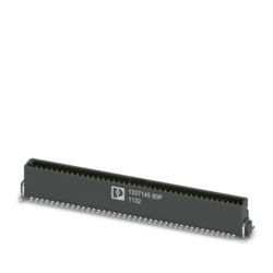
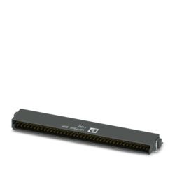
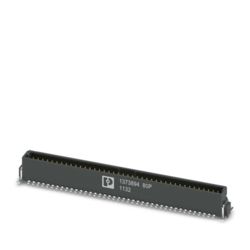
SMDメスコネクタ、 定格電流: 2.2 A、 試験電圧: 840 V AC、 極数: 80、 ピッチ: 1.27 mm、 色: 黒、 コンタクト表面: Au、 コンタクトタイプ: メス、 取付け方法: SMDハンダ接続
| 製品ライン | SMDメスコネクタ |
| 製品シリーズ | FR 1,27/...-FV 6,25 |
| 極数 | 80 |
| ピッチ | 1.27 mm |
| 行の数 | 2 |
| ピン配列 | 線形パッド形状 |
| 特性 | |
| 標準規格 IN | 2.2 A IEC 60512-5-2:2002-02 (20°C時、100極) |
| 接触抵抗 | 10 mΩ |
| 試験電圧 | 840 V AC IEC 60512-4-1:2003-05 |
| データ伝送 | |
| データ伝送速度 | 12 Gbps |
| 取付けタイプ | SMDハンダ接続 |
| ピン配列 | 線形パッド形状 |
| プロセスメモ | |
| プロセス | リフローはんだ付け |
| 吸湿感度レベル(MSL) | MSL 1 |
| 分類温度Tc | 260 °C |
| リフローでのはんだ付け回数 | 3 |
| 材質のデータ - コンタクト先 | |
| 注記 | WEEE / RoHS準拠、ウィスカフリー、IEC 60068-2-82/JEDEC JESD 201準拠 |
| コンタクト材質 | 銅合金 |
| 表面特性 | 選択的コーティング |
| 金属表面処理 コンタクト部(仕上) | 金 (Au) |
| 金属表面処理 コンタクト部(下地) | ニッケル (Ni) |
| 金属表面処理 はんだ付け部(仕上) | すず (Sn) |
| 金属表面処理 はんだ付け部(下地) | ニッケル (Ni) |
| 材質のデータ - ハウジング | |
| 色 (ハウジング) | 黒 (9005) |
| 絶縁材質 | LCP |
| 絶縁材質グループ | IIIb |
| CTI、IEC 60112準拠 | 150 |
| UL94難燃性クラス | V0 |
| 動作時の注記 | 動作中の許容電圧は、IEC 60664-1準拠の絶縁要件の範囲内での空間距離と沿面距離を考慮して、アプリケーションによって異なります。 |
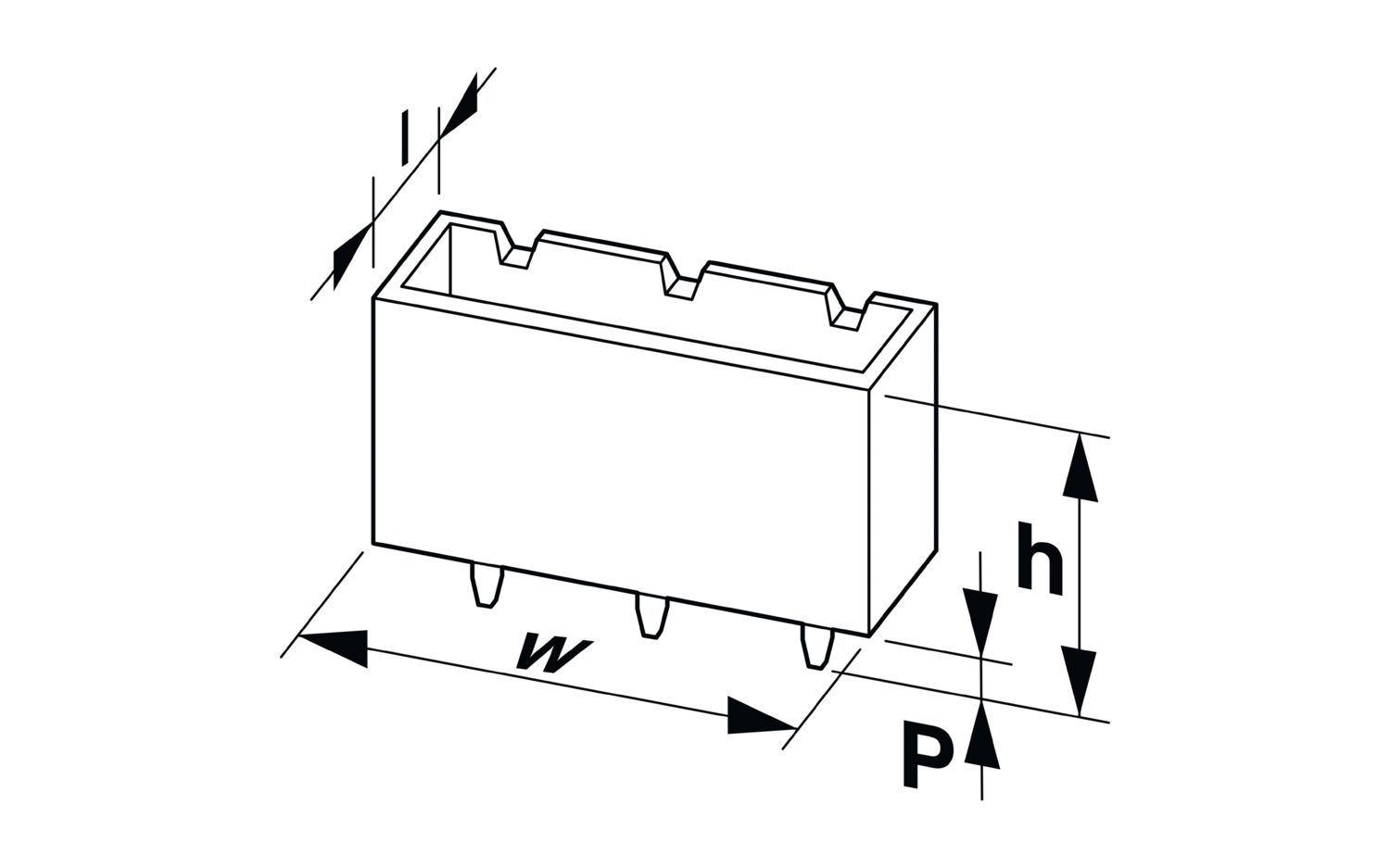
| 外形寸法 |
|
| ピッチ | 1.27 mm |
| 幅 [w] | 56.49 mm |
| 高さ [h] | 7 mm |
| 長さ[l] | 7.2 mm |
| 基板上高さ | 6.25 mm |
| アプリケーション | |
| コンタクトカバー | 0.9 mm |
| センターオフセット | ± 0.7 mm 縦方向と横方向 |
| スタック高さ | 8 mm 誤差範囲: +1.5 mm (組合せ時 製品範囲:FR 1,27/...-MV 1,75) |
| 9.5 mm 誤差範囲: +1.5 mm (組合せ時 製品範囲:FR 1,27/...-MV 3,25) | |
| 重複部分の長さ | 1.5 mm |
| 角度公差 | ± 5 ° 縦方向と横方向 |
| プリント基板設計 | |
| パッド形状 | 0.8 x 1.1 mm |
| 温度試験 | 試験グループC | |
| 仕様 | IEC 60512-5-2:2002-02 |
| 絶縁抵抗 | |
| 仕様 | IEC 60512-3-1:2002-02 |
| 絶縁抵抗、隣接する極 | ≥ 5 GΩ |
| 空間距離と沿面距離 | | |
| 絶縁材質グループ | IIIb |
| 空間距離および沿面距離の最小値 | 0.43 mm |
| 振動試験 | |
| 仕様 | IEC 60068-2-6:2007-12 |
| 周波数 | 10 - 2000 - 10 Hz |
| スイープ速度 | 1オクターブ/最小 |
| 振幅 | 1.5 mm (10 Hz ... 58 Hz) |
| 加速 | 200 m/s² (58 Hz ... 2000 Hz) |
| 各軸のテスト時間 | 2.5 h |
| 試験方向 | X、Y、Z軸 |
| 耐久試験 | |
| 仕様 | IEC 60512-9-1:2010-03(以下) |
| 接触抵抗R1 | 10 mΩ |
| 接触抵抗R2 | 15 mΩ |
| 挿抜回数 | 500 |
| 絶縁抵抗、隣接する極 | ≥ 5 GΩ |
| 衝撃試験 | |
| 仕様 | IEC 60068-2-27:2008-02 |
| パルス形状 | 半正弦波 |
| 加速 | 490 m/s² |
| 衝撃時間 | 11 ms |
| 試験方向 | X、Y、Z軸(正および負) |
| 周囲条件 | |
| 周囲温度(作動時) | -55 °C ... 125 °C |
| 周囲温度(保管時/運搬時) | -40 °C ... 70 °C |
| 相対湿度(保管時/運搬時) | 30 % ... 70 % |
| 周囲温度(配線時) | -5 °C ... 100 °C |
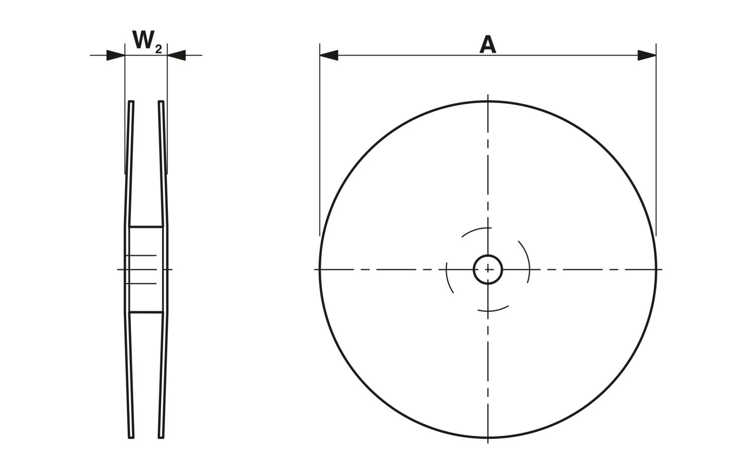
| 外形寸法 |
|
| 梱包の種類 | 72 mm幅のテープ |
| [W]テープ幅 | 72 mm |
| [W2]リール全体のサイズ | ≤ 78.4 mm |
| [A]リール径 | ≤ 330 mm |
| 外部梱包の種類 | 透明のバッグ |
| 定格電圧UN | 定格電流IN | 適合線サイズAWG | 適合線サイズ mm2 | |
|---|---|---|---|---|
| keine | ||||
| 29.9 V | 1.4 A | |||
| 定格電圧UN | 定格電流IN | 適合線サイズAWG | 適合線サイズ mm2 | |
|---|---|---|---|---|
| keine | ||||
| 29.9 V | 2 A | |||
特注のバージョンを入手することも可能ですか。
はい、標準製品に加えて、機器内のプリント基板接続用にお客様指定のバージョンも開発しています。お客様のご要求の設計や実施についてのご相談を承っております。
基板対基板コネクタFR 1,27の特長は何でしょうか。
接点あたりの定格電流を2.3 A超にすることも可能ですか。
現在、別のメーカー製の基板対基板コネクタ(1.27 mmピッチ)を使用しています。新しいFR 1,27に変更する場合、多額のコストがかかったり複雑だったりしますか。
いいえ、新しいコネクタFR 1,27は関連競合他社の製品とも互換性があります。対応する試験報告書はご要望に応じて提供可能です。
基板対基板コネクタFR 1,27シリーズで利用可能な極数はどれですか。
コネクタFR 1,27は、以下の極数でご利用可能です:6、12、16、20、26、32、40、50、68、80、100。
IDC式プラグコネクタには、12極、16極、20極、26極、32極、40極、50極、68極、80極のバージョンがあります。
Does the specified data transmission rate apply to all combinations?
No, the specified data transmission rate refers to an example combination. It may vary depending on the item combination. Factors such as different stack heights - due to longer or shorter contacts - influence the signal quality and thus the achievab... もっと見る
No, the specified data transmission rate refers to an example combination. It may vary depending on the item combination. Factors such as different stack heights - due to longer or shorter contacts - influence the signal quality and thus the achievable data rate. We can work with you to optimize high-speed data transmission for individual applications. Feel free to contact us.
もっと見るWhere is position 1?
Position a1 (row a, pin 1) is marked on the item. Position 1 is also marked in the TecDoc drawings (product family drawing and packaging drawing). The orientation of the item for PCB assembly and the plug-in direction are thus clearly defined. The cu... もっと見る
Position a1 (row a, pin 1) is marked on the item. Position 1 is also marked in the TecDoc drawings (product family drawing and packaging drawing). The orientation of the item for PCB assembly and the plug-in direction are thus clearly defined. The customer can provide a different definition in its own documentation.
もっと見るWhere can I find information on extended air clearances and creepage distances to realize the necessary voltage requirements in my application?
The minimum distances are specified in the technical data. We are happy to calculate distances for partially assembled connectors or between omitted pins (so-called death metal parts) on request. This means that increased voltage requirements can also be realized.
Where can I find out more about board-to-board connectors?
You can find white papers, new products, product information, videos, etc., under ’Board-to-board connectors’ in the ’Products’ section of our website. Download the ‘FINEPITCH board-to-board connectors’ brochure as an e-paper. This provides details o... もっと見る
You can find white papers, new products, product information, videos, etc., under ’Board-to-board connectors’ in the ’Products’ section of our website. Download the ‘FINEPITCH board-to-board connectors’ brochure as an e-paper. This provides details on applications, contact systems, and the technical properties of the products. It also provides information on data transmission, electromagnetic compatibility (EMC), and the SMD soldering process.
もっと見る