
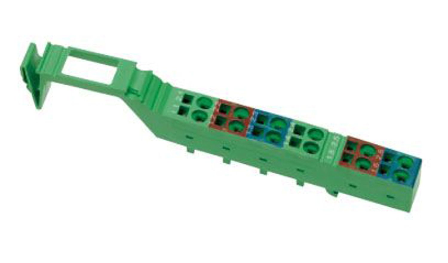
The terminal is designed for use within an Inline station. It is used to acquire digital signals. Thanks to special engineering measures and tests, the terminal can be used under extreme ambient conditions.
IB IL 24 DI 4-XC-PAC
-
Digital module
2701152
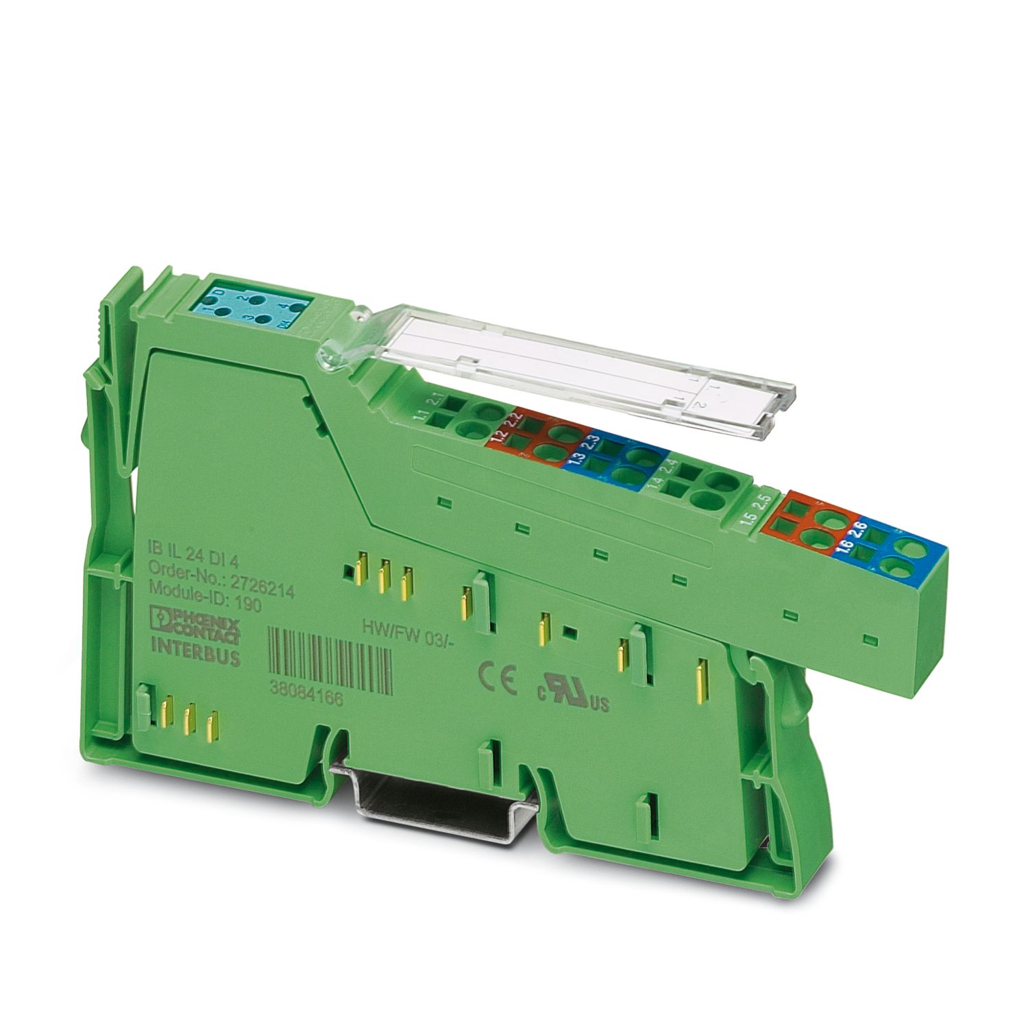

Inline, Digital input terminal, Digital inputs: 4, 24 V DC, connection technology: 3-conductor, Extreme conditions version, transmission speed in the local bus: 500 kbps, degree of protection: IP20, including Inline connector and labeling field
Maksuton lataus saatavilla.
Ladattavat tiedostot
Tuotetiedot
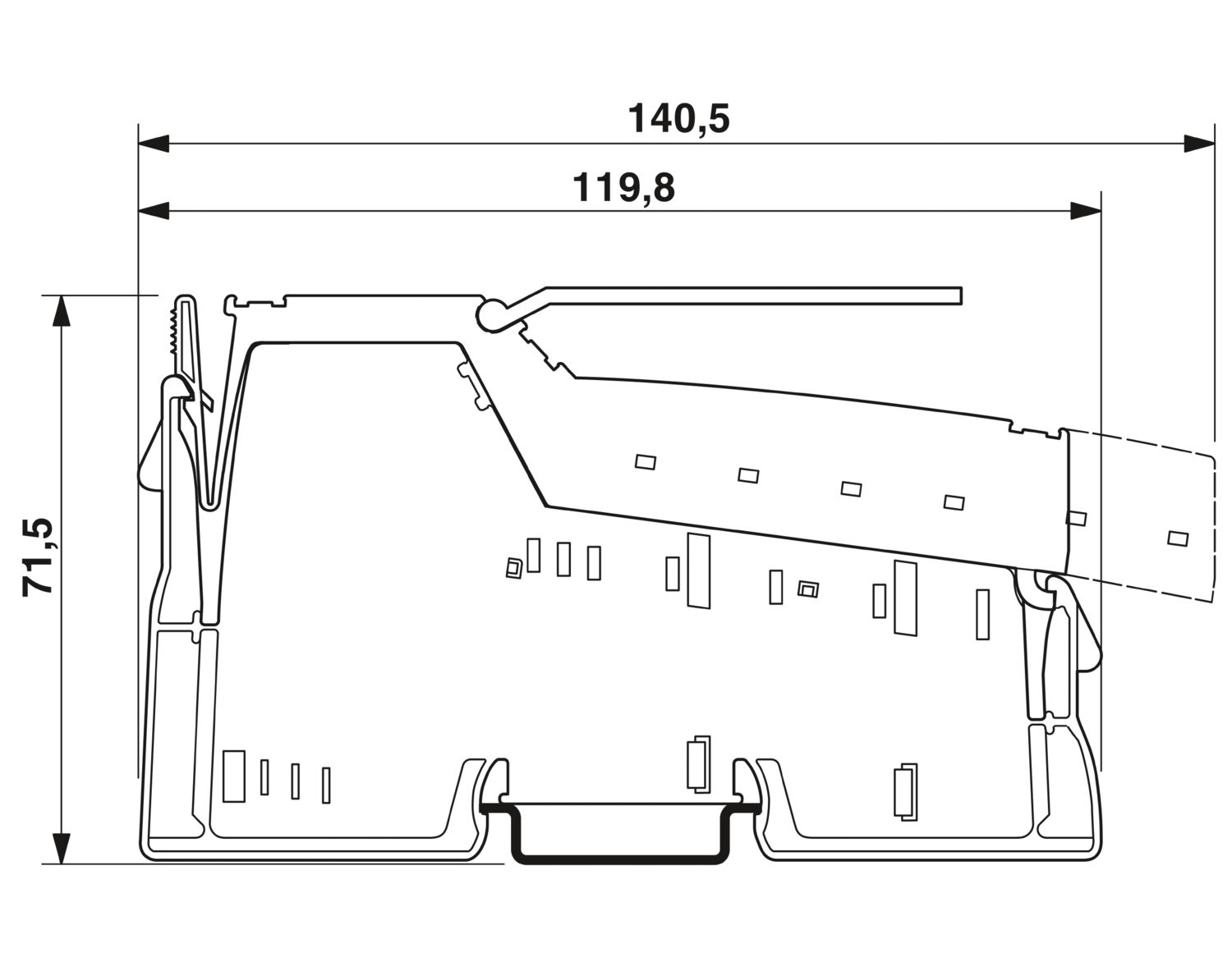
| Dimensional drawing |
|
| Width | 12.2 mm |
| Height | 140.5 mm |
| Depth | 71.5 mm |
| Note on dimensions | Housing dimensions |
| Note on application | |
| Note on application | Only for industrial use |
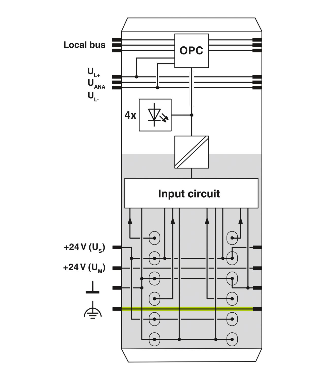
| Inline local bus | |
| Number of interfaces | 2 |
| Connection method | Inline data jumper |
| Transmission speed | 500 kbps |
| Module | |
| ID code (dec.) | 190 |
| ID code (hex) | BE |
| Length code (hex) | 41 |
| Length code (dec) | 65 |
| Process data channel | 4 bit |
| Input address area | 4 bit |
| Output address area | 0 Byte |
| Register length | 4 bit |
| Required parameter data | 1 Byte |
| Required configuration data | 4 Byte |
| Digital: | |
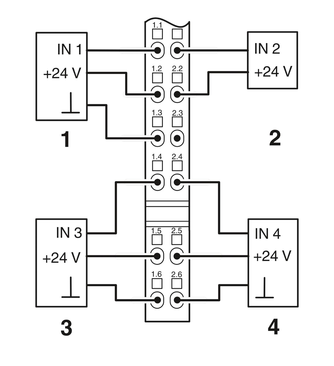
| Input name | Digital inputs |
| Description of the input | EN 61131-2 type 1 |
| Number of inputs | 4 |
| Connection method | Spring-cage connection |
| Connection technology | 3-conductor |
| Input voltage | 24 V DC |
| Input voltage range "0" signal | -3 V DC ... 5 V DC |
| Input voltage range "1" signal | 15 V DC ... 30 V DC |
| Nominal input voltage UIN | 24 V DC |
| Nominal input current at UIN | min. 3 mA (at nominal voltage) |
| Sensor current per channel | max. 250 mA |
| Typical response time | < 1 ms |
| Protective circuit | Short-circuit and overload protection |
| Product type | I/O component |
| Product family | Inline |
| Type | modular |
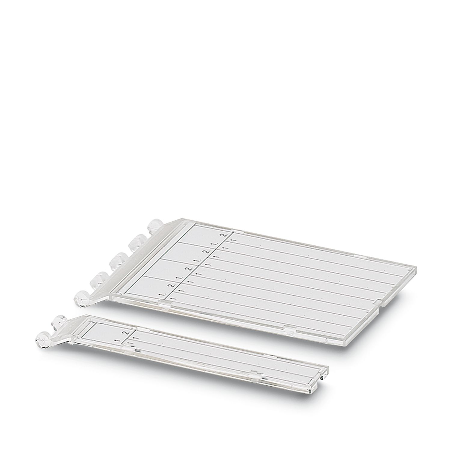
| Scope of supply | including Inline connector and labeling field |
| No. of channels | 4 |
| Operating mode | Process data operation with 4 bits |
| Special properties | Extreme conditions version |
| Protective circuit | Surge protection; Protective elements in the power terminal or the bus coupler |
| Reverse polarity protection; Protective elements in the power terminal or the bus coupler | |
| Potentials: Communications power (UL) | |
| Supply voltage | 7.5 V DC |
| Current draw | max. 40 mA |
| Potentials: Segment circuit supply (US) | |
| Supply voltage | 24 V DC (via voltage jumper) |
| Supply voltage range | 19.2 V DC ... 30 V DC (including all tolerances, including ripple) |
| Current draw | max. 1 A |
| 0 A | |
| Electrical isolation/isolation of the voltage ranges | |
| Test voltage: 5 V supply, incoming remote bus/7.5 V supply (bus logics) | 500 V AC, 50 Hz, 1 min |
| Test voltage: 5 V supply, outgoing remote bus/7.5 V supply (bus logics) | 500 V AC, 50 Hz, 1 min |
| Test voltage: 7.5 V supply (bus logics)/24 V supply (I/O) | 500 V AC, 50 Hz, 1 min |
| Test voltage: 24 V supply (I/O) / functional ground | 500 V AC, 50 Hz, 1 min |
| Connection technology | |
| Connection name | Inline connector |
| Conductor connection | |
| Connection method | Spring-cage connection |
| Conductor cross section rigid | 0.08 mm² ... 1.5 mm² |
| Conductor cross section flexible | 0.08 mm² ... 1.5 mm² |
| Conductor cross section AWG | 28 ... 16 |
| Stripping length | 8 mm |
| Inline connector | |
| Connection method | Spring-cage connection |
| Conductor cross section, rigid | 0.08 mm² ... 1.5 mm² |
| Conductor cross section, flexible | 0.08 mm² ... 1.5 mm² |
| Conductor cross section AWG | 28 ... 16 |
| Stripping length | 8 mm |
| Ambient conditions | |
| Ambient temperature (operation) | -25 °C ... 55 °C (Standard) |
| -40 °C ... 70 °C (Extended, see section “Tested successfully: use under extreme ambient conditions” in the data sheet.) | |
| Degree of protection | IP20 |
| Air pressure (operation) | 70 kPa ... 106 kPa (up to 3000 m above sea level) |
| Air pressure (storage/transport) | 70 kPa ... 106 kPa (up to 3000 m above sea level) |
| Ambient temperature (storage/transport) | -40 °C ... 85 °C |
| Permissible humidity (operation) | 10 % ... 95 % (according to DIN EN 61131-2) |
| Permissible humidity (storage/transport) | 10 % ... 95 % (according to DIN EN 61131-2) |
| Protection class | III (IEC 61140, EN 61140, VDE 0140-1) |
| Mounting type | DIN rail mounting |

Edut
4 digital inputs
Connection of sensors in 2- and 3-conductor technology
Maximum permissible load current per sensor: 250 mA
Maximum permissible load current from the terminal: 1 A
Can be used under extreme ambient conditions
Extended temperature range of -40 °C ... +70 °C (see “Tested successfully: use under extreme ambient conditions” in the data sheet)
Coated PCBs