
Active redundancy module for superior system availability and maximum operational reliability. QUINT S-ORING enables the separate structuring of a redundant system. In combination with the new QUINT POWER power supply, the redundant system is monitored continuously.
QUINT4-S-ORING/12-24DC/1X40
-
Redundancy module
2907752
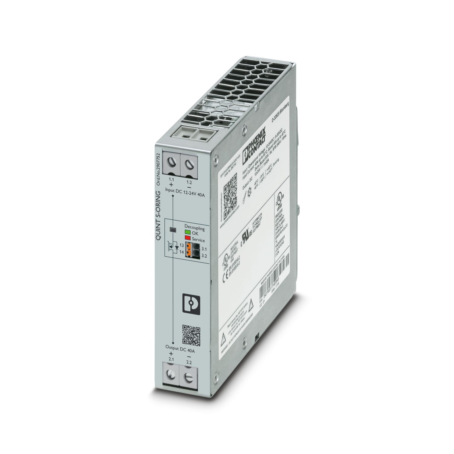

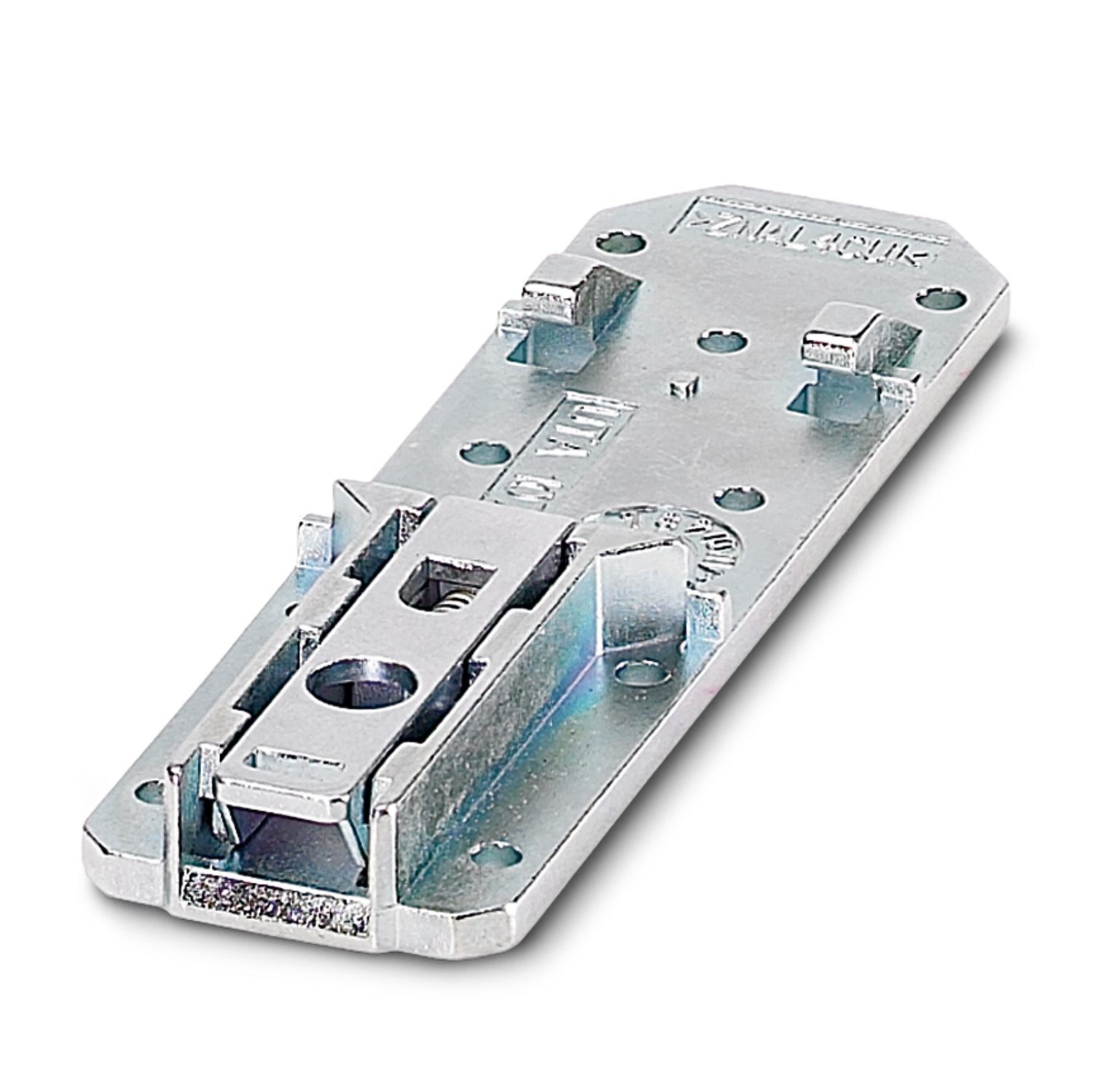
Active QUINT single redundancy module for DIN rail mounting, input: 12 V DC ... 24 V DC, output: 12 V DC ... 24 V DC / 1 x 40 A, incl. mounted UTA 107/30 universal DIN rail adapter
Detalii despre produs
| DC operation | |
| Nominal input voltage range | 12 V DC ... 24 V DC |
| Input voltage range | 8 V DC ... 30 V DC (SELV) |
| Typical national grid voltage | 12 V DC |
| 24 V DC | |
| Voltage type of supply voltage | DC |
| Current consumption | 40 A |
| Static Boost (IStat.Boost) | 45 A |
| Dynamic Boost (IDyn.Boost) | 60 A (5 s) |
| Selective Fuse Breaking (ISFB) | 215 A (15 ms) |
| Reverse polarity protection | yes, < 60 V |
| Nominal input current (IN) | 40 A (-40 °C ... 60 °C) |
| Input current IStatic | 45 A (40 °C) |
| Input current IDynamic | 60 A (5 s) |
| Input current ISFB | 215 A (15 ms) |
| Transient surge protection | Varistor |
| Voltage drop, input/output | 0.1 V DC |
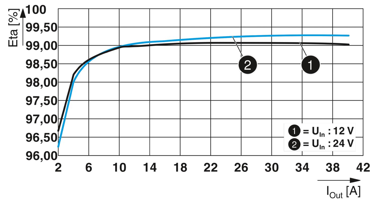
| Efficiency | typ. 99.1 % (12 V DC) |
| typ. 99.3 % (24 V DC) | |
| Nominal output voltage | UIn - 0,1 V DC |
| Nominal output current (IN) | 40 A |
| Static Boost (IStat.Boost) | 45 A |
| Dynamic Boost (IDyn.Boost) | 60 A (5 s) |
| Selective Fuse Breaking (ISFB) | 215 A (15 ms) |
| Derating | 60 °C ... 70 °C (2.5 %/K) |
| Power loss nominal load max. | 6.5 W (IOUT = 40 A) |
| 6 W (IOUT = 40 A) | |
| Connection in series | no |
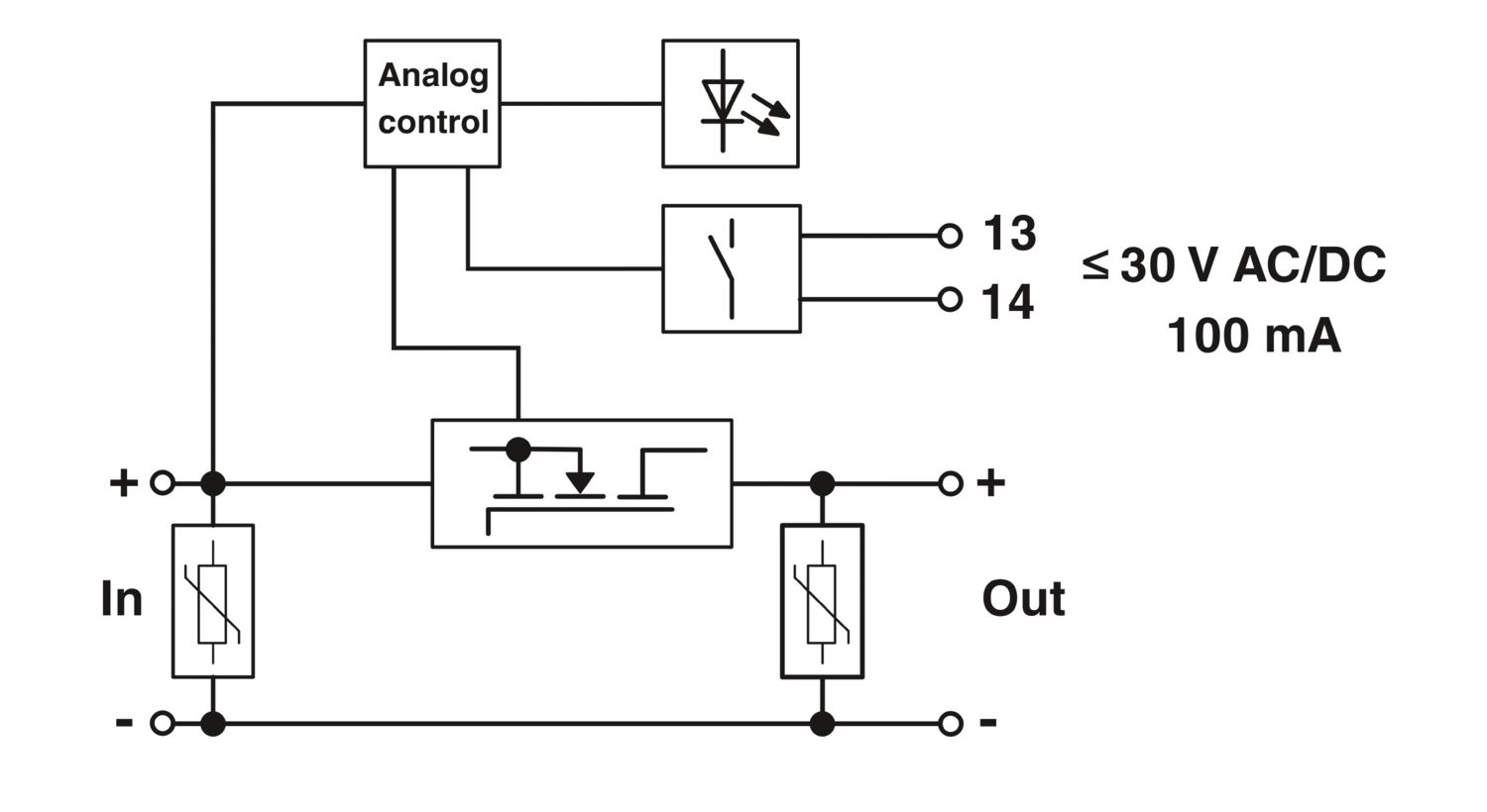
| Signal: OK, 13/14 | |
| Output description | Group contact |
| Maximum switching voltage | max. 30 V AC/DC |
| Maximum inrush current | ≤ 100 mA (short-circuit-proof) |
| Signal relay 13/14 | |
| Default | open |
| Additional text | UIN < 8 V DC |
| Signal relay 13/14 | |
| Default | closed |
| Additional text | UIN > 8 V DC |
| Signal relay 13/14 | |
| Default | open |
| Additional text | Redundancy module defective |
| Input | |
| Connection method | Screw connection |
| Conductor cross-section, rigid min. | 0.5 mm² |
| Conductor cross-section, rigid max. | 16 mm² |
| Conductor cross-section flexible min. | 0.5 mm² |
| Conductor cross-section flexible max. | 16 mm² |
| Single conductor/flexible terminal point with ferrule with plastic sleeve, min. | 0.5 mm² |
| Single conductor/flexible terminal point with ferrule with plastic sleeve, max. | 16 mm² |
| Single conductor/flexible terminal point with ferrule without plastic sleeve, min. | 0.5 mm² |
| Single conductor/flexible terminal point with ferrule without plastic sleeve, max. | 16 mm² |
| Conductor cross-section AWG min. | 20 |
| Conductor cross-section AWG max. | 6 |
| Stripping length | 10 mm |
| Screw thread | M4 |
| Tightening torque, min | 1.2 Nm |
| Tightening torque max | 1.5 Nm |
| Output | |
| Connection method | Screw connection |
| Conductor cross-section, rigid min. | 0.5 mm² |
| Conductor cross-section, rigid max. | 16 mm² |
| Conductor cross-section flexible min. | 0.5 mm² |
| Conductor cross-section flexible max. | 16 mm² |
| Single conductor/flexible terminal point with ferrule with plastic sleeve, min. | 0.5 mm² |
| Single conductor/flexible terminal point with ferrule with plastic sleeve, max. | 16 mm² |
| Single conductor/flexible terminal point with ferrule without plastic sleeve, min. | 0.5 mm² |
| Single conductor/flexible terminal point with ferrule without plastic sleeve, max. | 16 mm² |
| Conductor cross-section AWG min. | 20 |
| Conductor cross-section AWG max. | 6 |
| Stripping length | 10 mm |
| Screw thread | M4 |
| Tightening torque, min | 1.2 Nm |
| Tightening torque max | 1.5 Nm |
| Signal | |
| Connection method | Push-in connection |
| Conductor cross-section, rigid min. | 0.2 mm² |
| Conductor cross-section, rigid max. | 1.5 mm² |
| Conductor cross-section flexible min. | 0.2 mm² |
| Conductor cross-section flexible max. | 1.5 mm² |
| Single conductor/flexible terminal point with ferrule with plastic sleeve, min. | 0.2 mm² |
| Single conductor/flexible terminal point with ferrule with plastic sleeve, max. | 0.75 mm² |
| Single conductor/flexible terminal point with ferrule without plastic sleeve, min. | 0.2 mm² |
| Single conductor/flexible terminal point with ferrule without plastic sleeve, max. | 1.5 mm² |
| Conductor cross-section AWG min. | 24 |
| Conductor cross-section AWG max. | 16 |
| Stripping length | 8 mm |
| Types of signaling | Relay contact, floating, current limited |
| Signal output: OK, 13/14 | |
| UIn < 8 V DC | LED off, input voltage not present or short circuit at redundancy module output |
| UIn > 8 V DC | LED lights up green, input voltage present |
| Redundancy modul faulty | LED lights up red, redundancy module needs to be factory tested |
| Insulation voltage input, output / housing | 500 V DC |
| Product type | Redundancy module |
| Product family | QUINT S-ORING |
| MTBF (IEC 61709, SN 29500) | > 25297000 h (25 °C) |
| > 15153000 h (40 °C) | |
| > 7449000 h (60 °C) | |
| LED | yes |
| Insulation characteristics | |
| Protection class | III |
| Degree of pollution | 2 |
| Life expectancy (electrolytic capacitors) | |
| Current | 40 A |
| Temperature | 40 °C |
| Time | 186000 h |
| Additional text | 12 V DC |
| Life expectancy (electrolytic capacitors) | |
| Current | 40 A |
| Temperature | 40 °C |
| Time | 123000 h |
| Additional text | 24 V DC |
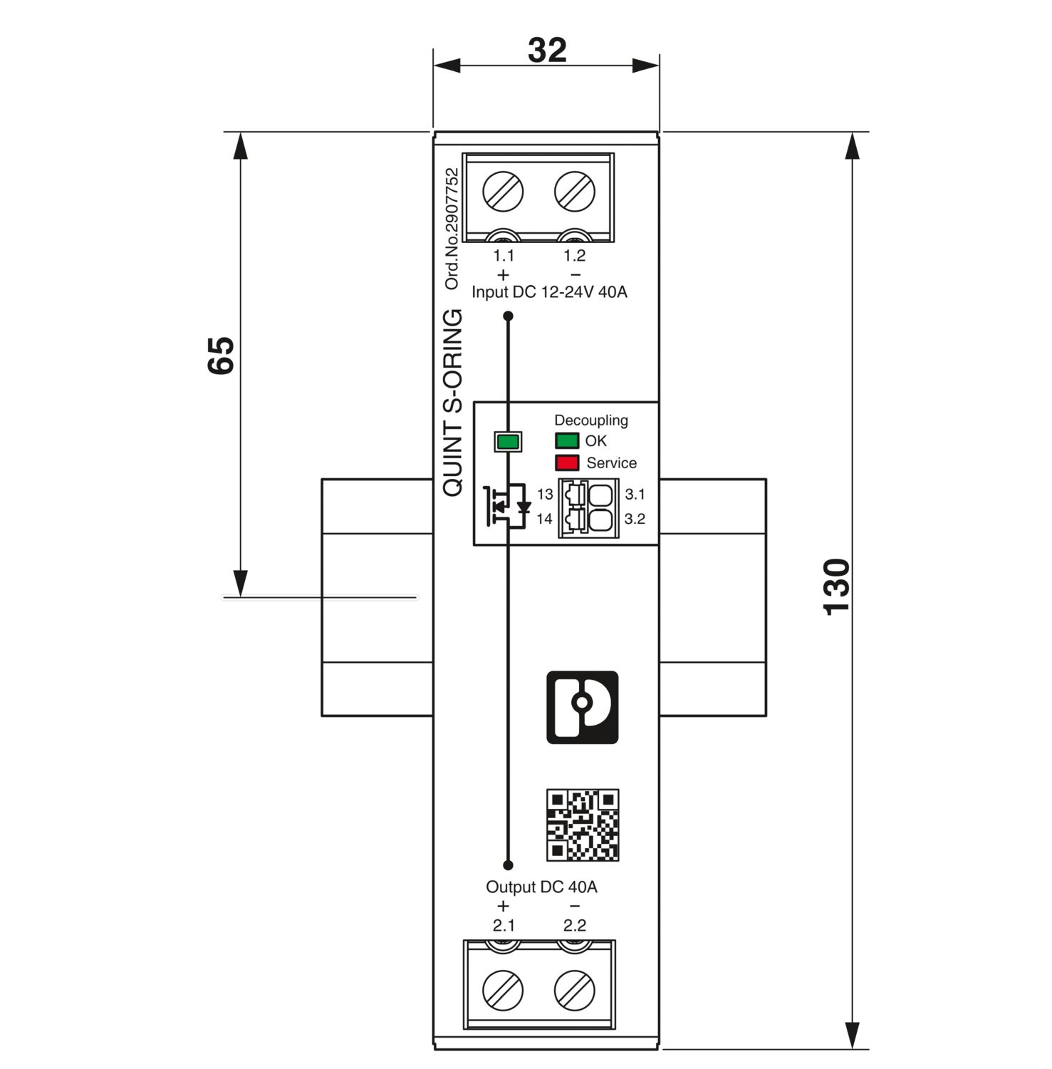
| Dimensional drawing |
|
| Width | 32 mm |
| Height | 130 mm |
| Depth | 125 mm |
| Installation dimensions | |
| Installation distance right/left | 0 mm / 0 mm |
| Installation distance top/bottom | 40 mm / 20 mm |
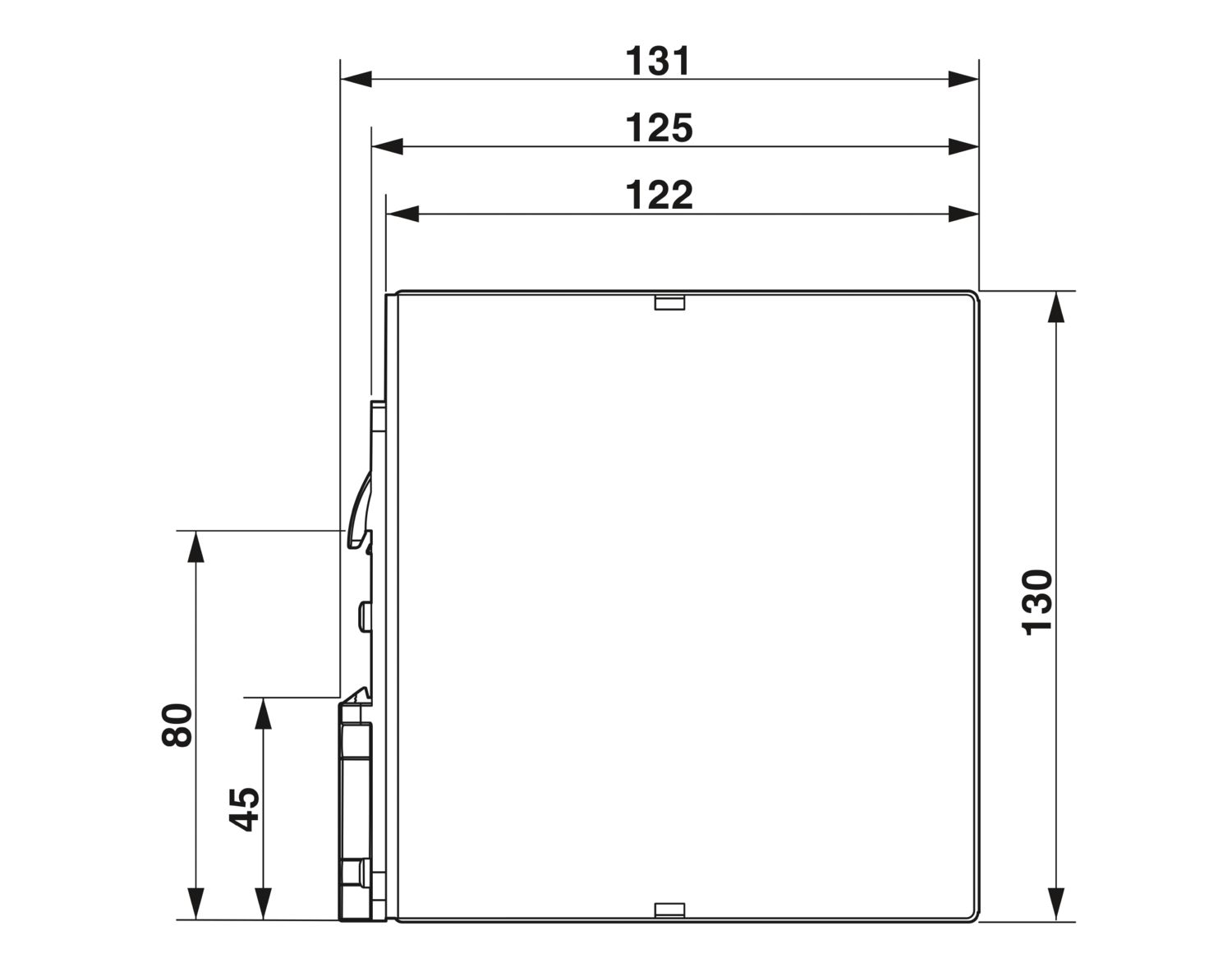
| Alternative assembly | |
| Width | 122 mm |
| Height | 130 mm |
| Depth | 35 mm |
| Mounting type | DIN rail mounting |
| Assembly note | alignable: PN ≥50%, 5 mm horizontally, 15 mm next to active components, 50 mm vertically alignable: PN <50%, 0 mm horizontally, 40 mm vertically top, 20 mm vertically bottom |
| Mounting position | horizontal DIN rail NS 35, EN 60715 |
| Flammability rating according to UL 94 (housing / terminal blocks) | V0 |
| Housing material | Metal |
| Housing material | Aluminum / stainless steel |
| Type of housing | Aluminum (AlMg3) |
| Hood version | Galvanized sheet steel, free from chrome (VI) |
| Ambient conditions | |
| Degree of protection | IP20 |
| Ambient temperature (operation) | -40 °C ... 70 °C (> 60 °C Derating: 2,5 %/K) |
| Ambient temperature (storage/transport) | -40 °C ... 85 °C |
| Maximum altitude | ≤ 5000 m (> 2000 m, observe derating) |
| Climatic class | 3K22 (in accordance with EN 60721-3-3) |
| Max. permissible relative humidity (operation) | ≤ 95 % (at 25 °C, non-condensing) |
| Shock | 18 ms, 30g, in each space direction (according to IEC 60068-2-27) |
| Vibration (operation) | < 15 Hz, amplitude ±2.5 mm (according to IEC 60068-2-6) |
| 15 Hz ... 150 Hz, 2.3g, 90 min. | |
| Temp code | T4 (-25 ... +70 °C; > 60 °C, Derating: 2,5 %/K) |
| Standard - Electrical safety | IEC 62368-1 |
| Standard – Safety extra-low voltage | IEC 62368-1 |
| Shipbuilding approval | DNV, NK |
| UL approvals | UL/C-UL listed UL 508 |
| UL/C-UL Recognized UL 60950-1 | |
| UL 121201 & CSA C22.2 No. 213-17 Class I, Division 2, Groups A, B, C, D T4 (Hazardous Location) | |
| Conformity/Approvals | |
| SIL in accordance with IEC 61508 | 0 |
| Electromagnetic compatibility | Conformance with EMC Directive 2014/30/EU |
| Low Voltage Directive | Conformance with Low Voltage Directive 2014/35/EC |
| EMC requirements for noise emission | EN 61000-6-3 |
| EN 61000-6-4 | |
| EMC requirements for noise immunity | EN 61000-6-1 |
| EN 61000-6-2 | |
| Conducted noise emission | |
| Standards/regulations | EN 55016 |
| EN 61000-6-3 (Class B) | |
| Noise emission | |
| Standards/regulations | Additional basic standard EN 61000-6-5 (immunity in power station) |
| Noise emission | |
| Standards/regulations | EN 55016 |
| EN 61000-6-3 (Class B) | |
| DNV GL conducted noise emissions | |
| DNV | Class A |
| Additional text | Area power distribution |
| DNV GL noise radiation | |
| DNV | Class B |
| Additional text | Bridge and deck area |
| Electrostatic discharge | |
| Standards/regulations | EN 61000-4-2 |
| Electrostatic discharge | |
| Contact discharge | 8 kV (Test Level 4) |
| Discharge in air | 15 kV (Test Level 4) |
| Comments | Criterion A |
| Electromagnetic HF field | |
| Standards/regulations | EN 61000-4-3 |
| Electromagnetic HF field | |
| Frequency range | 80 MHz ... 1 GHz |
| Test field strength | 20 V/m (Test Level 3) |
| Frequency range | 1 GHz ... 6 GHz |
| Test field strength | 10 V/m (Test Level 3) |
| Comments | Criterion A |
| Fast transients (burst) | |
| Standards/regulations | EN 61000-4-4 |
| Fast transients (burst) | |
| Input | 2 kV (Test Level 3 - asymmetrical) |
| Output | 2 kV (Test Level 3 - asymmetrical) |
| Signal | 2 kV (Test Level 4 - asymmetrical) |
| Comments | Criterion B |
| Surge voltage load (surge) | |
| Standards/regulations | EN 61000-4-5 |
| Surge voltage load (surge) | |
| Input | 1 kV (Test Level 3 - symmetrical) |
| 2 kV (Test Level 3 - asymmetrical) | |
| Output | 1 kV (Test Level 3 - symmetrical) |
| 2 kV (Test Level 3 - asymmetrical) | |
| Signal | 1 kV (Test Level 2 - asymmetrical) |
| Comments | Criterion A |
| Conducted interference | |
| Standards/regulations | EN 61000-4-6 |
| Conducted interference | |
| Input/output/signal | asymmetrical |
| Frequency range | 0.15 MHz ... 100 MHz |
| Comments | Criterion A |
| Voltage | 20 V (Test Level 3) |
| Criteria | |
| Criterion A | Normal operating behavior within the specified limits. |
| Criterion B | Temporary impairment to operational behavior that is corrected by the device itself. |
UL Recognized
ID de înregistrare: E211944EAC
ID de înregistrare: RU S-DE.BL08.W.00764UL Listed
ID de înregistrare: E123528cUL Listed
ID de înregistrare: E123528DNV
ID de înregistrare: TAA000011FIECEE CB Scheme
ID de înregistrare: DE/PTZ/0048NK
ID de înregistrare: TA25015MUL Recognized
ID de înregistrare: E211944IECEE CB Scheme
ID de înregistrare: DE/PTZ/0048EAC
ID de înregistrare: RU S-DE.BL08.W.00764cUL Recognized
ID de înregistrare: E211944cUL Listed
ID de înregistrare: E123528UL Listed
ID de înregistrare: E123528NK
ID de înregistrare: TA25015MDNV
ID de înregistrare: TAA000011FcUL Listed
ID de înregistrare: E199827UL Listed
ID de înregistrare: E199827UL Listed
ID de înregistrare: E199827cUL Listed
ID de înregistrare: E199827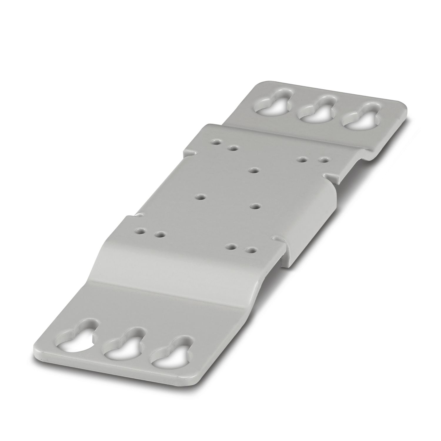
Avantajele dumneavoastră
Consistent redundancy up to the load
Input voltage and decoupling section monitored on a permanent basis
Save energy by decoupling with MOSFET
Întrebări frecvente
Do I only need one QUINT4-S-ORING/12-24DC/1X40 to decouple two power supplies from each other?
No, one QUINT4-S-ORING/12-24DC/1X40 is required for each power supply. The potentials must be brought together at the output of the S-ORING
modules. With this module, n+1 redundancy can thus be set up in the simplest way.
Does the item have integrated surge protection?
No. For surge voltages from 28.8 V, we recommend the QUINT4-S-ORING/12-24DC/1X40/+. For surge voltages from 30 V, we recommend the QUINT4-S-ORING/12-24DC/1X40/VP.