
TRIO-PM/1AC/24DC/2500W
-
Power supply
1635194
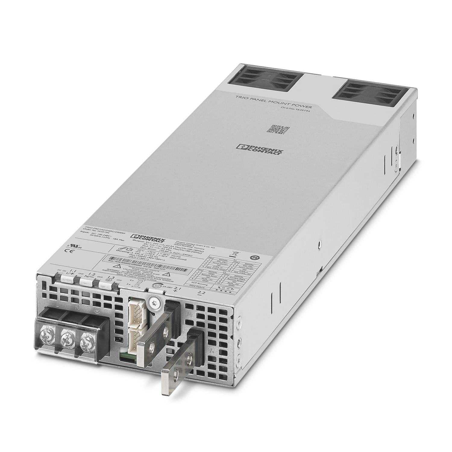

Primary-switched power supply unit, TRIO POWER, Screw connection, CAN bus, Panel mounting, input: 1-phase, output: 24 V DC / 104 A, adjustable from 24 V DC ... 28 V DC
Докладно про виріб
| AC operation | |
| Supply system configuration | Star network (TN, TT, IT (PE)) |
| Nominal input voltage range | 100 V AC ... 240 V AC |
| Input voltage range | 100 V AC ... 240 V AC -15 % ... +10 % |
| 100 V AC ... 240 V AC ±10 % (UL) | |
| Derating | 85 V AC ... 90 V AC (≤1350 W) |
| 90 V AC ... 180 V AC (≤ 1500 W) | |
| 2.5 %/K, > 55 ℃ | |
| Electric strength, max. | 300 V AC 15 s |
| Typical national grid voltage | 120 V AC |
| 230 V AC | |
| Voltage type of supply voltage | AC |
| Inrush current | < 15 A (115 V AC, 25 °C) |
| < 40 A (230 V AC, 25 °C) | |
| Inrush current integral (I2t) | < 3364 A2s |
| Frequency range (fN) | 50 Hz ... 60 Hz ±5 % |
| Mains buffering time | typ. 10 ms (120 V AC) |
| typ. 10 ms (230 V AC@80% load) | |
| Buffer time | typical 16 ms (120 V AC) |
| typical 16 ms (230 V AC@80% load) | |
| Current consumption | 16.7 A (100 V AC) |
| 20 A (85 V AC) | |
| 15 A (180 V AC) | |
| 11.7 A (230 V AC) | |
| max. 18 A (UL) | |
| Protective circuit | Transient protection |
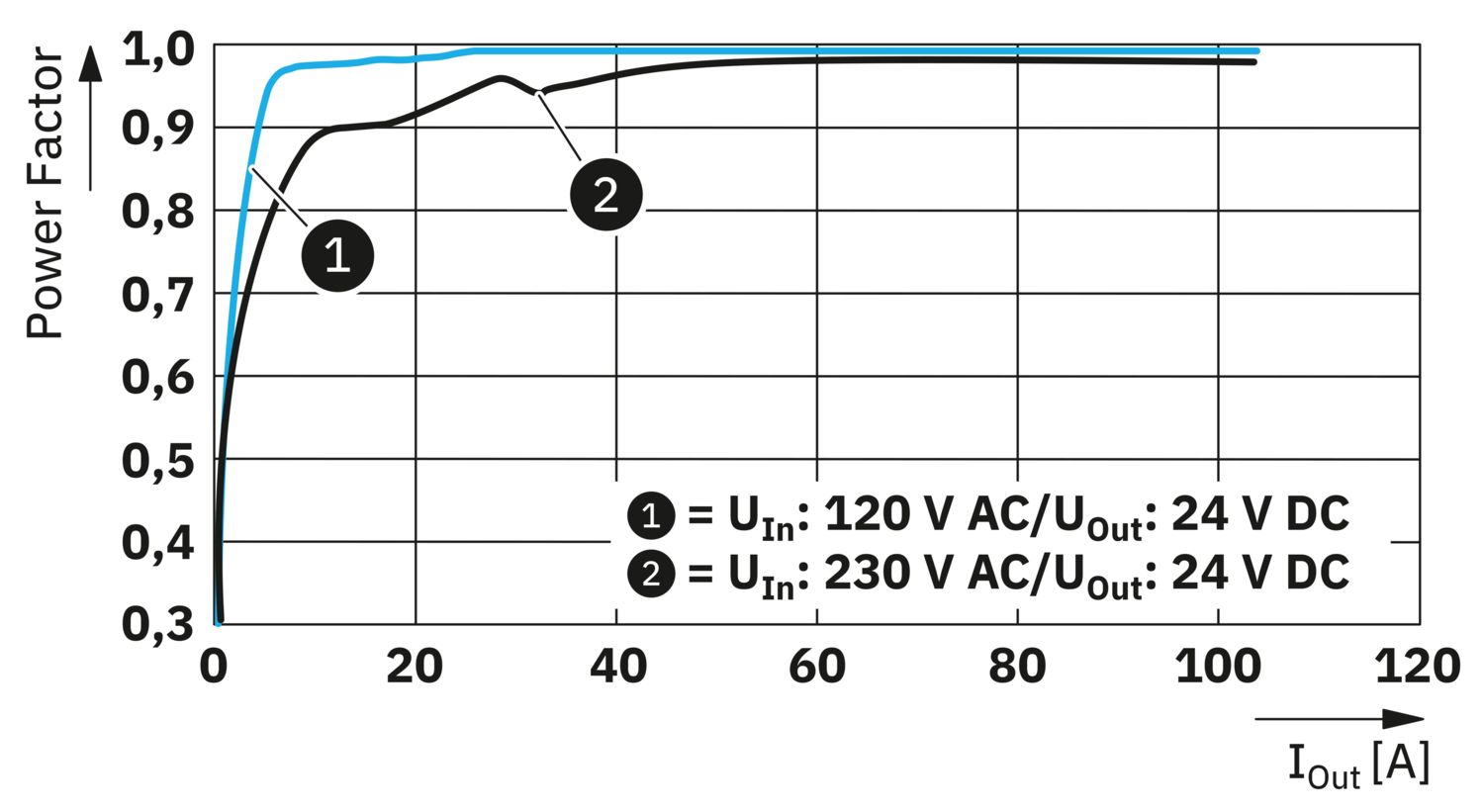
| Power factor (cos phi) | 0.97 (230 V AC) |
| Device mains fuse | 25 A internal (device protection) |
| Discharge current to PE | < 2 mA |
| DC operation | |
| Input voltage range | 140 V DC ... 340 V DC -15 %; +10 % |
| Current consumption | 13.8 A (120 V DC) |
| 7.6 A (350 V DC) | |
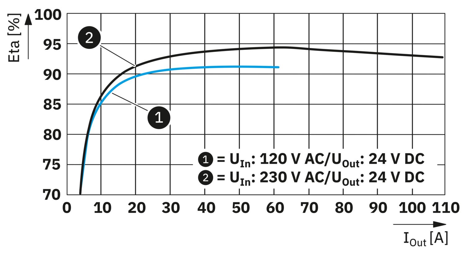
| Efficiency | typ. 92 % (120 V AC) |
| typ. 93.5 % (230 V AC) | |
| Nominal output voltage | 24 V DC |
| Setting range of the output voltage (USet) | 24 V DC ... 28 V DC (> 24 V DC, constant capacity restricted) |
| Nominal output current (IN) | 104 A |
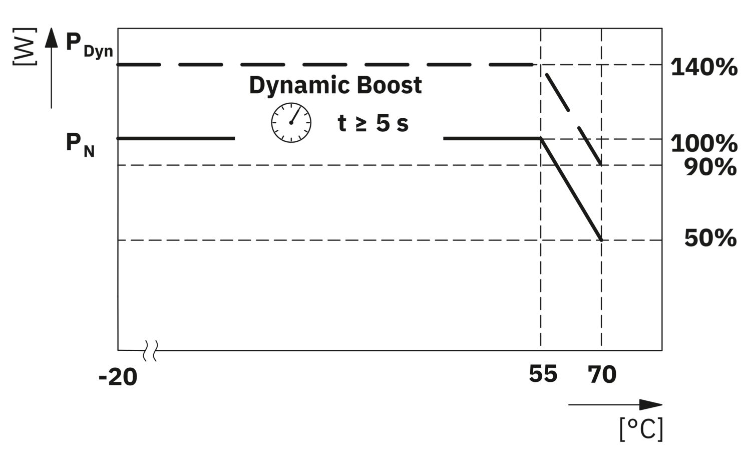
| Dynamic Boost (IDyn.Boost) | max. 145.8 A (5 s) |
| Short-circuit-proof | yes |
| No-load proof | yes |
| Crest factor | typ. 1.43 (120 V AC) |
| typ. 1.44 (230 V AC) | |
| Output power | max. 1500 W (< 180 V AC) |
| Output power (PN) | 2500 W |
| Output power (PDyn. Boost) | max. 3500 W (5 s) |
| Connection in parallel | yes, for increased efficiency and redundancy |
| max. 4 | |
| Connection in series | yes, for increased output voltage (observe SELV limit) |
| max. 2 | |
| Feedback voltage resistance | ≤ 35 V DC |
| Protection against overvoltage at the output (OVP) | ≤ 35 V DC |
| Residual ripple | typ. 240 mVPP (maximum) |
| Control deviation | < 0.5 % (change in load, static 10 % ... 90 %) |
| < 5 % (change in load, dynamic 10 % ... 90 %) | |
| < 0.5 % (change in input voltage ±10 %) | |
| Rise time | ≤ 100 ms (UOut = 10 % ... 90 %) |
| Minimum no-load power dissipation | < 17.67 W (120 V AC) |
| Maximum no-load power dissipation | < 10.75 W (230 V AC) |
| Minimum nominal load power dissipation | < 138.32 W (120 V AC) |
| Power loss nominal load max. | < 175.36 W (230 V AC) |
| Integrated fuse protection | yes |
| Input | |
| Position | 1.x |
| Connection technology | |
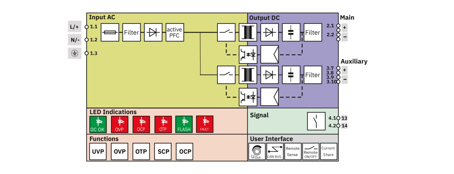
| Position marking | 1.1 (L/+), 1.2 (N/-), 1.3 () |
| Conductor connection | |
| Connection method | Screw connection |
| rigid | 1.3 mm² ... 3 mm² |
| 2.5 mm² (recommended) | |
| flexible | 1.3 mm² ... 3 mm² |
| 2.5 mm² (recommended) | |
| flexible with ferrule without plastic sleeve | 1.3 mm² ... 3 mm² |
| 2.5 mm² (recommended) | |
| flexible with ferrule with plastic sleeve | 1.3 mm² ... 3 mm² |
| 2.5 mm² (recommended) | |
| AWG | 18 ... 12 (Cu) |
| 14 (recommended) | |
| Stripping length | 10 mm (Rigid/flexible/ferrule) |
| Tightening torque | 1.13 Nm ... 1.47 Nm |
| 10 lbf-in. ... 13 lbf-in. | |
| Output | |
| Position | 2.x |
| Connection technology | |
| Position marking | 2.1 (+), 2.2 (-) |
| Conductor connection | |
| Connection method | Screw connection (Busbar) |
| rigid | 0.2 mm² ... 35 mm² |
| 35 mm² (recommended) | |
| flexible | 0.2 mm² ... 35 mm² |
| 35 mm² (recommended) | |
| AWG | 6 ... 2 (Cu) |
| 2 (recommended) | |
| Stripping length | 10 mm (rigid/flexible/ring cable lug/fork-type cable lug) |
| Tightening torque | 3 Nm |
| Signal, communication | |
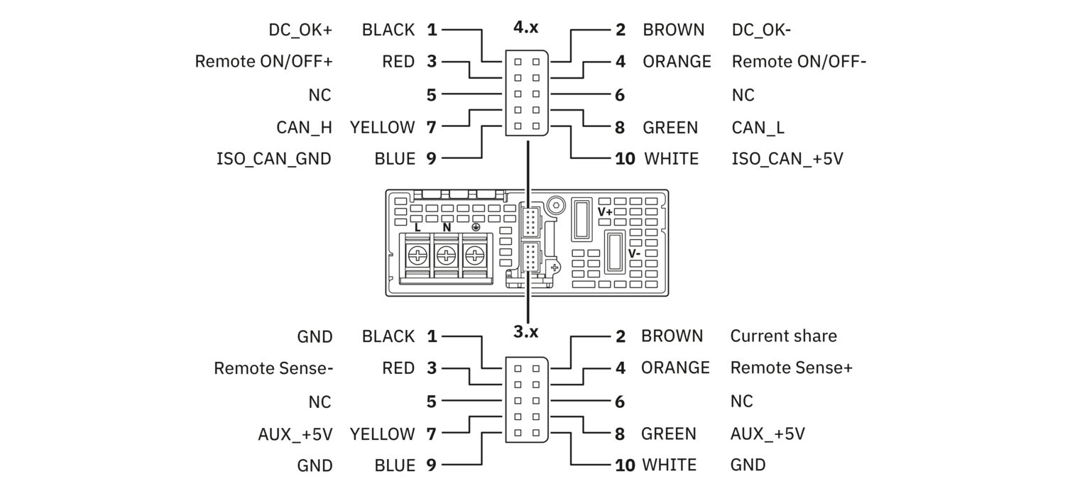
| Position | 3.x, 4.x |
| Connection technology | |
| Position marking | 3.1 - 3.10, 4.1 - 4.10 |
| Conductor connection | |
| Connection method | 2x 10-pos. pin strip |
| rigid | 0.1 mm² ... 0.4 mm² |
| 0.34 mm² (recommended) | |
| flexible | 0.1 mm² ... 0.4 mm² |
| 0.34 mm² (recommended) | |
| flexible with ferrule without plastic sleeve | 0.1 mm² ... 0.4 mm² (Cu) |
| 0.34 mm² (recommended) | |
| flexible with ferrule with plastic sleeve | 0.1 mm² ... 0.4 mm² |
| 0.34 mm² (recommended) | |
| AWG | 30 ... 22 (Cu) |
| 22 (recommended) | |
| CAN-Bus | |
| Interface | CAN bus |
| Number of interfaces | 1 |
| Connection method | 10-pos. system connector |
| Supported protocols | CAN 2.0A, CAN 2.0B |
| Locking | Locking clip |
| Transmission physics | wired |
| Topology | Daisy Chain |
| Transmission speed | 250 kbps |
| Transmission length | max. 20 m |
| Termination resistor | 120 Ω (Terminating the end device) |
| Number of bus devices | max. 16 |
| LED signaling | |
| Types of signaling | LED DC OK - signal state operation (UN = 24 V DC, IOut = IN) |
| Function | Visualization of the operating state of the DC output voltage (DC OK) |
| Color | Red, green (multicolor LED) |
| LED off | Supply voltage input AC not present (Off) |
| LED on (green), DC OK | UOutSet x 0.95 < UOut < UOutSet x 1.05 and IOut < IN (On (green), DC OK) |
| LED on (flashing green) | UOutSet x 1.05 < UOut < UOutSet x 1.1 orUOutSet x 0.9 < UOut < UOutSet x 0.95 orIN < IOut < IN x 1.1 (on (flashing green)) |
| LED on (red) | UOutSet x 0.9 > UOut orUOutSet x 1.1 < UOut orIOut > IN x 1.1, continuously for 6 s (on (red)) |
| LED signaling | |
| Types of signaling | LED OVP - signal state operation (UN = 24 V DC, IOut = IN) |
| Function | Visualization of the surge protection operating state (OVP) |
| Color | Red, green (multicolor LED) |
| LED off | Supply voltage input AC not present (Off) |
| LED on (green) | UOUT < UOutSet x 1.1 (on (green)) |
| LED on (flashing green) | UOutSet x 1.1 < UOut < OVP (on (flashing green)) |
| LED on (red) | UOut > OVP (on (red)) |
| LED signaling | |
| Types of signaling | LED OCP - signal state operation (UN = 24 V DC, IOut = IN) |
| Function | Visualization of the overcurrent protection operating state (OCP) |
| Color | Red, green (multicolor LED) |
| LED off | Supply voltage input AC not present (Off) |
| LED on (green) | IOut < IN x 1.1 (on (green)) |
| LED on (flashing green) | IN x 1.1 < IOut < IN x 1.3 (on (flashing green)) |
| LED on (red) | IOut > IN x 1.3 continuously for 6 s (on (red)) |
| LED signaling | |
| Types of signaling | LED OTP - signal state operation (UN = 24 V DC, IOut = IN) |
| Function | Visualization of the overtemperature protection operating state (OTP) |
| Color | Red, green (multicolor LED) |
| LED off | Supply voltage input AC not present |
| LED on (green) | TAmb < OTP - 10 °C (on (green)) |
| LED on (flashing green) | OTP - 10 °C < TAmb < OTP (on (flashing green)) |
| LED on (red) | OTP < TAmb (on (red)) |
| LED signaling | |
| Types of signaling | LED FAN - signal state operation (UN = 24 V DC, IOut = IN) |
| Function | Visualization of the operating state of the fan (in operation or malfunction) |
| Color | Red, green (multicolor LED) |
| LED on (green) | FAN normal operation (on (4 x LED green)) |
| LED on (red) | FAN failure (on (4 x LED red)) |
| LED signaling | |
| Types of signaling | LED SCP - signal state operation (UN = 24 V DC, IOut = IN) |
| Function | Visualization of the short-circuit protection operating state (SCP) |
| Color | Red, green (multicolor LED) |
| LED on (flowing red) | Short circuit (on (4 x LED red continuous)) |
| LED signaling | |
| Types of signaling | LED Charging Mode – signal state operation (UN = 24 V DC, IOut = IN) |
| Function | Visualization of the charging mode |
| Color | Red, green (multicolor LED) |
| LEDs on (green flashing) | Charging mode activated (on (4 x LED green flashing)) |
| Signal state | |
| State condition | 0.95 * UOutSet |
| Signal output DC OK | |
| Position | 4.x |
| Type of signaling | DC OK switch contact - signal state operation (UN = 24 V DC, IOut = IN) |
| Position marking | 4.1 (13), 4.2 (14) |
| Function | Operating state forwarding |
| Switch contact (floating) | OptoMOS |
| Switching voltage | max. 30 V DC (SELV) |
| Current carrying capacity | max. 100 mA |
| State condition (Contact closed) | Uout < 18 V DC (Contact closed) |
| State condition (Contact open) | Uout > 18 V DC (Contact open) |
| Number of phases | 1 |
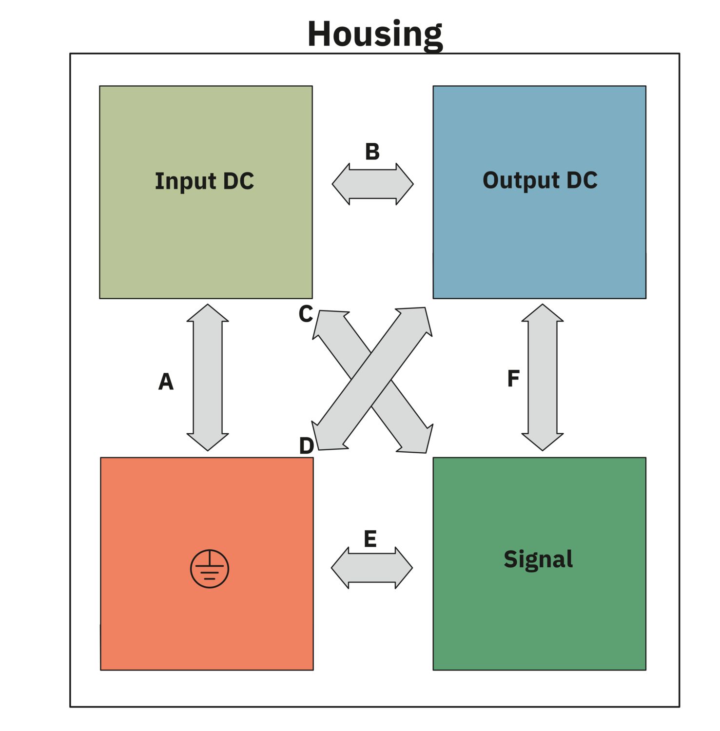
| Insulation voltage input/output | 4 kV AC (type test) |
| 1.5 kV AC (routine test) |
| Product type | Power supply |
| Product family | TRIO POWER |
| MTBF (IEC 61709, SN 29500) | > 500000 h (25 °C) |
| > 250000 h (40 °C) | |
| > 100000 h (55 °C) | |
| Environmental protection directive | RoHS Directive 2011/65/EU |
| Reach | |
| Insulation characteristics | |
| Protection class | I |
| Degree of pollution | 2 |
| Life expectancy (electrolytic capacitors) | |
| Temperature | 25 °C |
| Additional text | 8 years |
| Item dimensions | |
| Width | 108 mm |
| Height | 41 mm |
| Depth | 322 mm |
| Mounting type | Panel mounting |
| Assembly note | Side mounting: 3x M4 screws - installation depth < 4 mm Back mounting: 4x M4 screws - installation depth < 3 mm Mounting with Assembly adapter UWA 20/13 (Item no. 1697537) |
| With protective coating | no |
| Flammability rating according to UL 94 | V0 (Housing, terminal blocks) |
| Hood version | Aluminum (AlMg3) |
| Side element version | Aluminum |
| Ambient conditions | |
| Degree of protection | IP20 |
| Ambient temperature (operation) | -20 °C ... 70 °C (>55 °C Derating: 3,33 %/K) |
| Ambient temperature (storage/transport) | -40 °C ... 85 °C |
| Ambient temperature (start-up type tested) | -40 °C |
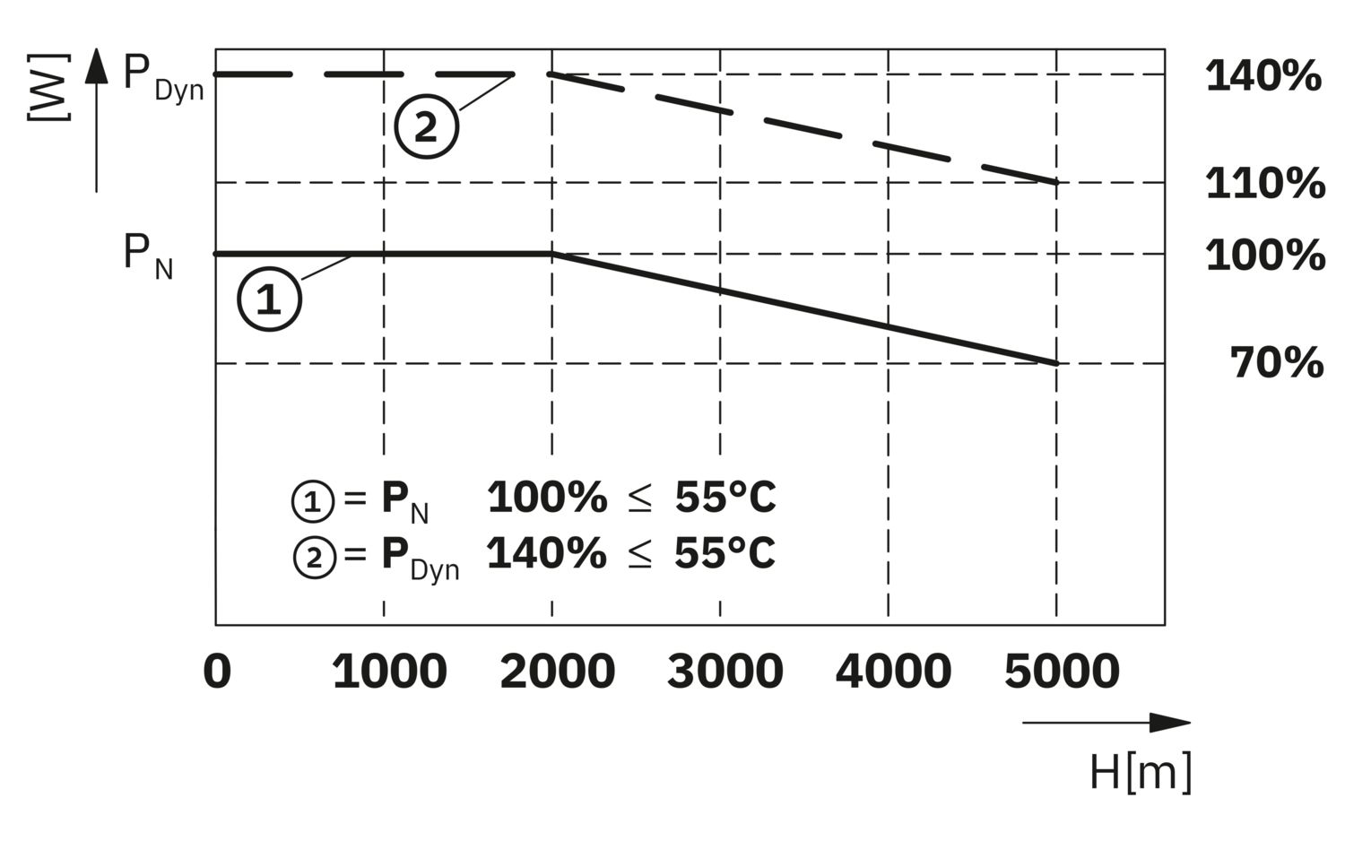
| Maximum altitude | ≤ 5000 m |
| Maximum altitude (Output power derating) | > 2000 m (Derating: 10%/1000 m) |
| Max. permissible relative humidity (operation) | ≤ 95 % (at 25 °C, non-condensing) |
| Shock (operation) | 11 ms, 15g, per spatial direction (IEC 60068-2-27) |
| Vibration (operation) | 10 Hz ... 18.2 Hz, amplitude ±0.75 mm (IEC 60068-2-6) |
| 18.2 Hz ... 150 Hz, 1g, 90 min. | |
| Overvoltage category | |
| EN 61010-1 | III (≤ 2000 m) |
| II (≤ 5000 m) | |
| Overvoltage category | |
| EN 61010-2-201 | III (≤ 2000 m) |
| II (≤ 5000 m) | |
| Safety of power supply units up to 1100 V (insulation distances) | |
| Standard designation | Safety of power supply units up to 1100 V (insulation distances) |
| Standards/specifications | DIN EN 61558-2-16 |
| Electrical safety | |
| Standard designation | Electrical safety |
| Standards/specifications | IEC 61010-2-201 (SELV) |
| Safety for measurement, control, and laboratory equipment | |
| Standard designation | Safety for equipment for measurement, control, and laboratory use |
| Standards/specifications | IEC 61010-1 |
| Protective extra-low voltage | |
| Standard designation | Protective extra-low voltage |
| Standards/specifications | IEC 61010-1 (SELV) |
| IEC 61010-2-201 (PELV) | |
| Safe isolation | |
| Standard designation | Safe isolation |
| Standards/specifications | IEC 61010-2-201 |
| Limitation of harmonic line currents | |
| Standard designation | Limitation of harmonic line currents |
| Standards/specifications | EN 61000-3-2 |
| Mains variation/undervoltage | |
| Standard designation | Mains variation/undervoltage |
| Standards/specifications | SEMI F47 - 0706 |
| UL | |
| Identification | UL/C-UL Listed UL 61010-1 |
| UL | |
| Identification | UL/C-UL Listed UL 61010-2-201 |
| UL | |
| Identification | UL/C-UL Approved UL 62368-1 |
| Electromagnetic compatibility | Conformance with EMC Directive 2014/30/EU |
| Low Voltage Directive | Conformance with Low Voltage Directive 2014/35/EC |
| EMC requirements for noise emission | EN 61000-6-3 |
| Noise immunity | Immunity in accordance with EN 61000-6-1 (residential), EN 61000-6-2 (industrial) |
| Conducted noise emission | |
| Standards/regulations | EN 55016 |
| EN 61000-6-4 (Class A) | |
| Noise emission | |
| Standards/regulations | EN 55016 |
| EN 61000-6-4 (Class A) | |
| Harmonic currents | |
| Standards/regulations | EN 61000-3-2 |
| EN 61000-3-2 (Class A) | |
| Frequency range | 0 kHz ... 2 kHz |
| Flicker | |
| Standards/regulations | EN 61000-3-3 |
| EN 61000-3-3 | |
| Electrostatic discharge | |
| Standards/regulations | EN 61000-4-2 |
| Electrostatic discharge | |
| Contact discharge | 4 kV (Test Level 3) |
| Discharge in air | 8 kV (Test Level 3) |
| Comments | Criterion A |
| Electromagnetic HF field | |
| Standards/regulations | EN 61000-4-3 |
| Electromagnetic HF field | |
| Frequency range | 80 MHz ... 1 GHz |
| Test field strength | 10 V/m (Test Level 3) |
| Frequency range | 1 GHz ... 6 GHz |
| Test field strength | 10 V/m (Test Level 3) |
| Comments | Criterion A |
| Fast transients (burst) | |
| Standards/regulations | EN 61000-4-4 |
| Fast transients (burst) | |
| Input | asymmetrical 2 kV (Test Level 3) |
| Output | asymmetrical 2 kV (Test Level 3) |
| Signal | asymmetrical 1 kV (Test Level 3) |
| Comments | Criterion B |
| Surge voltage load (surge) | |
| Standards/regulations | EN 61000-4-5 |
| Surge voltage load (surge) | |
| Input | symmetrical 2 kV (Test Level 4) |
| asymmetrical 4 kV (Test Level 4) | |
| Output | symmetrical 0.5 kV (Test Level 2) |
| asymmetrical 1 kV (Test Level 2) | |
| Signal | asymmetrical 1 kV (Test Level 2) |
| Comments | Criterion B |
| Conducted interference | |
| Standards/regulations | EN 61000-4-6 |
| Conducted interference | |
| Input/output/signal | asymmetrical |
| Frequency range | 0.15 MHz ... 80 MHz |
| Comments | Criterion A |
| Voltage | 10 V (Test Level 3) |
| Voltage dips | |
| Standards/regulations | EN 61000-4-11 |
| Voltage | 230 V AC |
| Frequency | 50 Hz |
| Voltage dip | 70 % |
| Number of periods | 25 periods |
| Additional text | Class 3 |
| Comments | Criterion A |
| Voltage dip | 40 % |
| Number of periods | 10 periods |
| Additional text | Class 3 |
| Comments | Criterion B |
| Voltage dip | 0 % |
| Number of periods | 1 period |
| Additional text | Class 3 |
| Comments | Criterion A |
| Criteria | |
| Criterion A | Normal operating behavior within the specified limits. |
| Criterion B | Temporary impairment to operational behavior that is corrected by the device itself. |
| Criterion C | Temporary adverse effects on the operating behavior, which the device corrects automatically or which can be restored by actuating the operating elements. |
| Артикул | 1635194 |
| Пакувальна одиниця | 1 Шт. |
| Мінімальний обсяг замовлення | 1 Шт. |
| Код виробу | CMHW13 |
| GTIN | 4067923157835 |
| Маса штуки (з упаковкою) | 2 392 g |
| Маса штуки (без упаковки) | 2 000 g |
| Митний тарифний номер | 85044095 |
| Країна походження | CN |
ECLASS
| ECLASS-13.0 | 27040701 |
| ECLASS-15.0 | 27040701 |
ETIM
| ETIM 9.0 | EC002540 |
| EU RoHS | |
| Відповідає вимогам Директиви RoHS | Так |
| винятки, якщо відомі | 6(c), 7(c)-I |
| China RoHS | |
| Environment friendly use period (EFUP) |
EFUP-25
Пов’язану зі статтею таблицю декларації RoHS для Китаю можна знайти в області завантаження для відповідного товару в розділі «Декларація виробника». Таблиця декларації RoHS для Китаю не видається й не вимагається для всіх товарів з позначкою EFUP-E.
|
| EU REACH SVHC | |
| Інформація щодо речовини-кандидата за Регламентом REACH (№ CAS) | Lead (№ CAS: Не застосовується) |
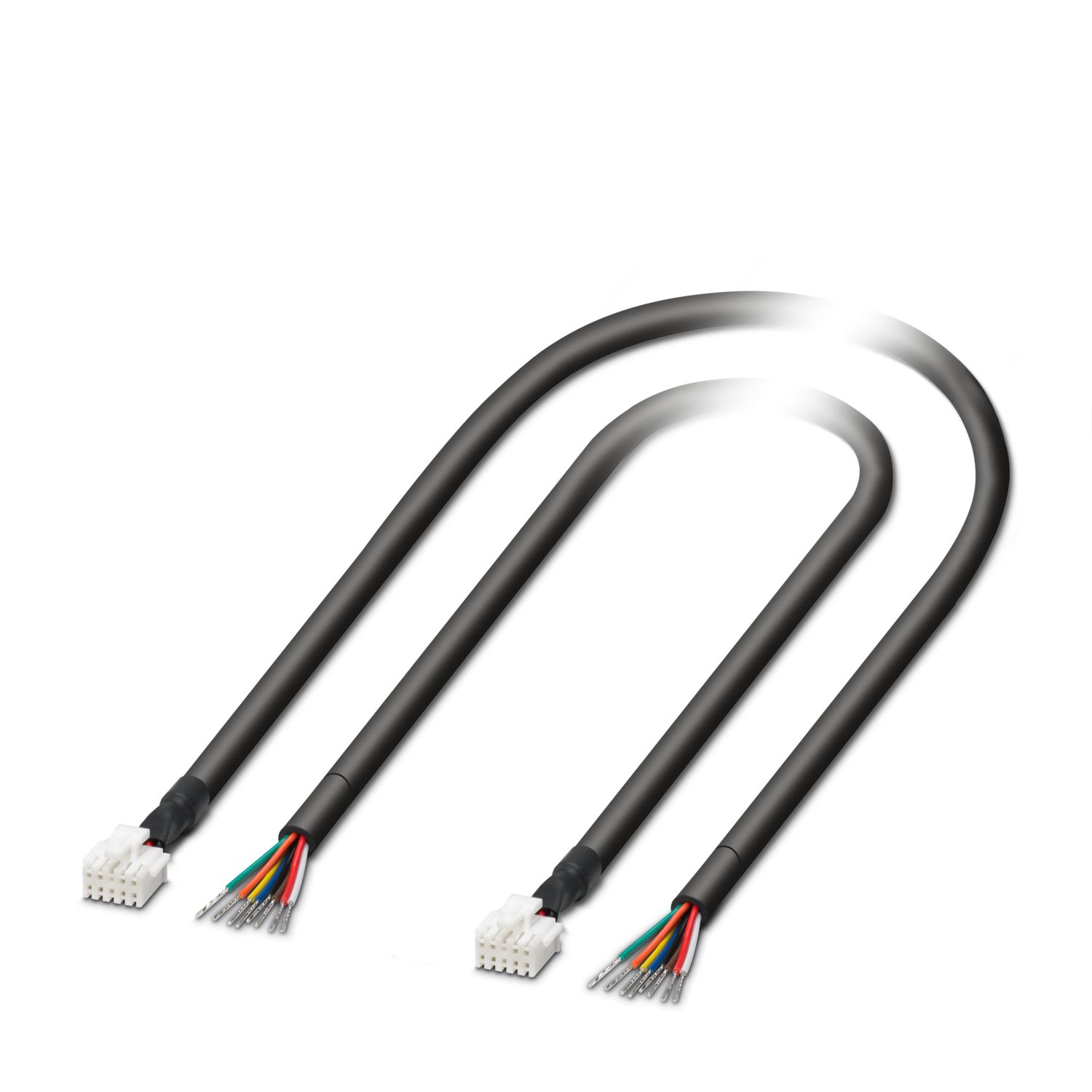
Сумісна продукція
-
TRIO PM CJT-A2008H-2X5P-OE - Data cable 1697887
-
UWA 20/13 - Mounting adapter 1697537
-
C-RC 35/M6 DIN - Ring cable lug 3240105
-
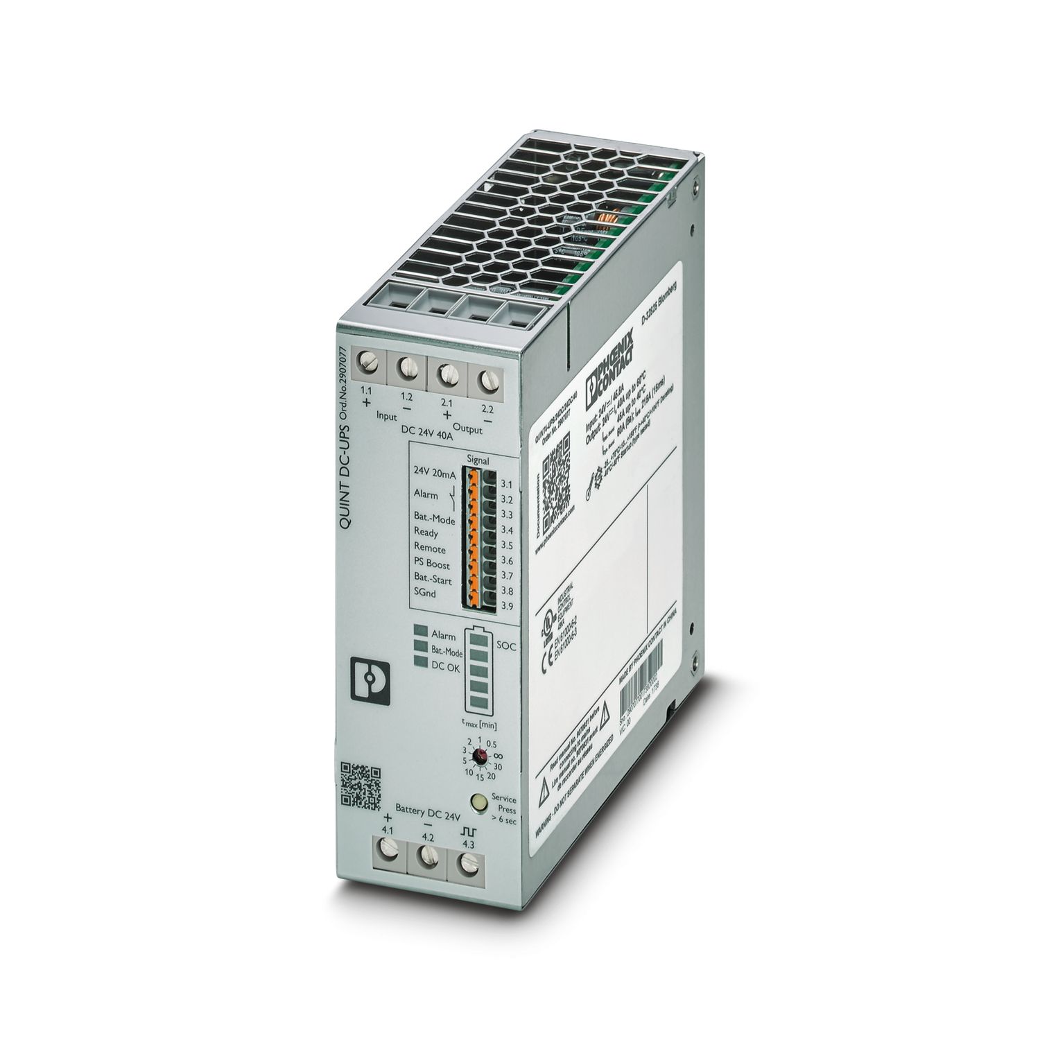
QUINT4-UPS/24DC/24DC/40 - Uninterruptible power supply 2907077
-
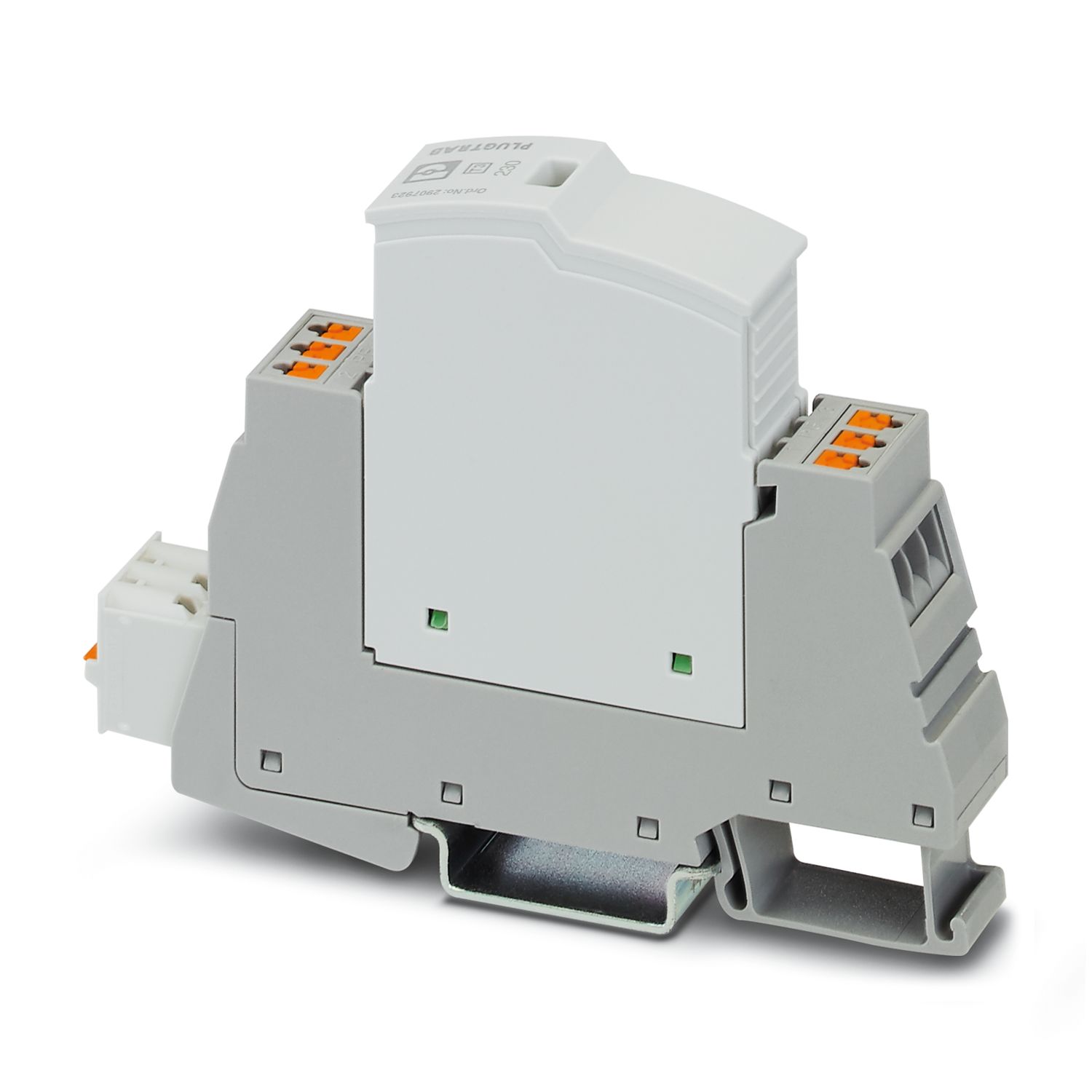
PLT-SEC-T3-230-FM-PT - Type 3 surge protection device 2907928
-
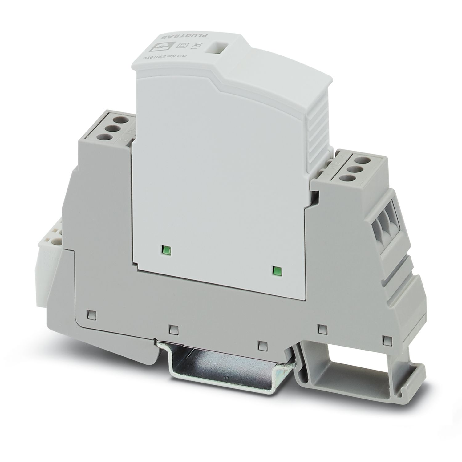
PLT-SEC-T3-120-FM-UT - Type 3 surge protection device 2907918
-
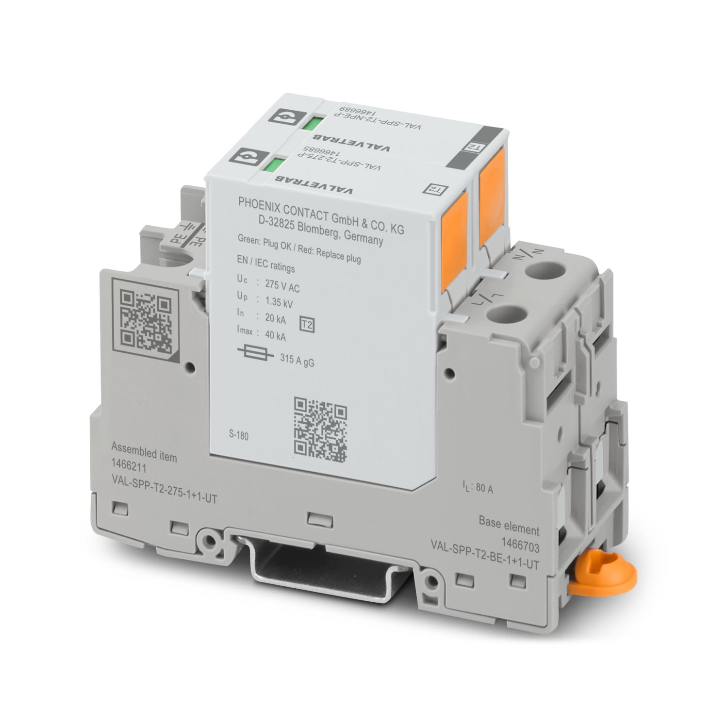
VAL-SPP-T2-275-1+1-UT - Type 2 surge arrester 1466211
-
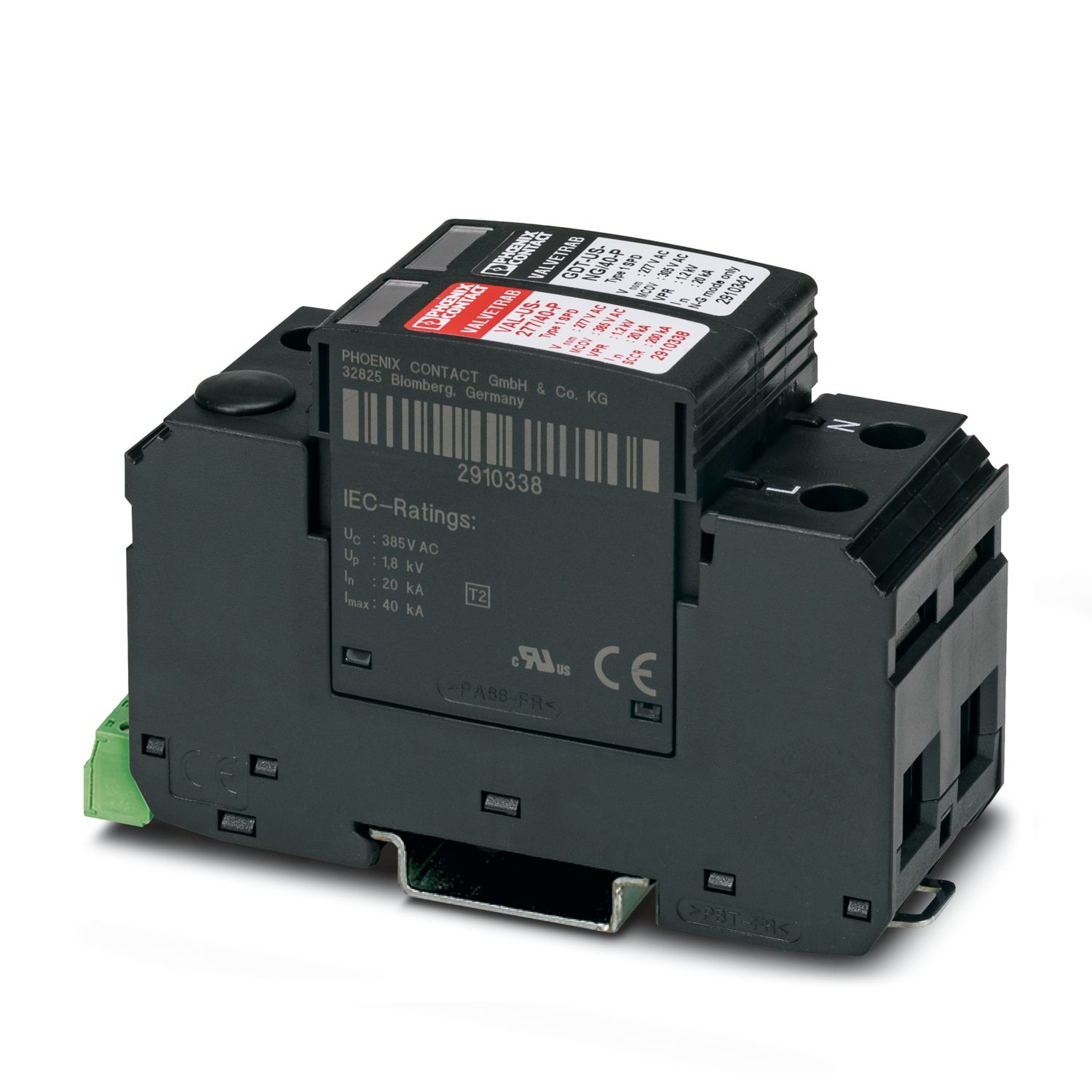
VAL-US-120/40/1+1-FM - Surge protection device 2910349
-
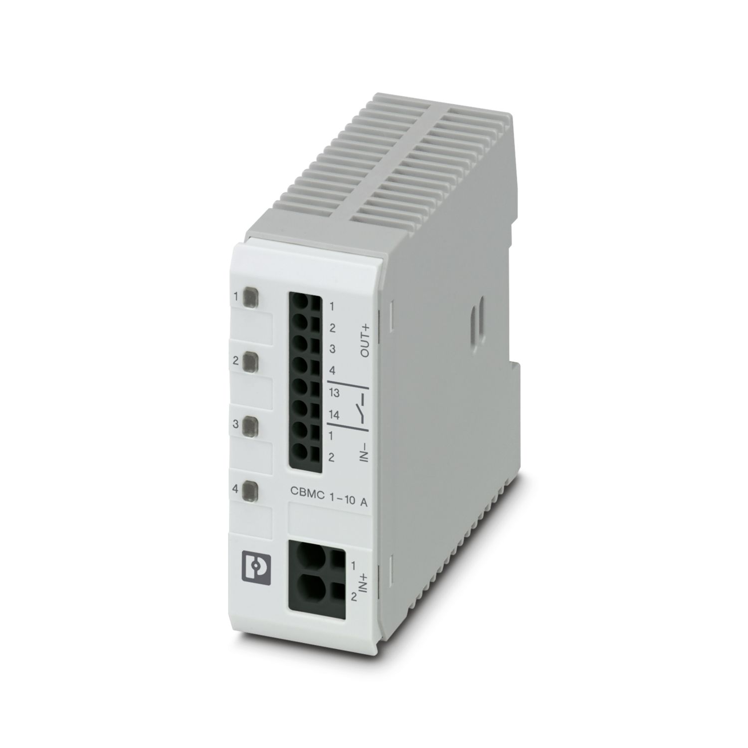
CBMC E4 24DC/1-10A NO - Electronic circuit breaker 2906032
-
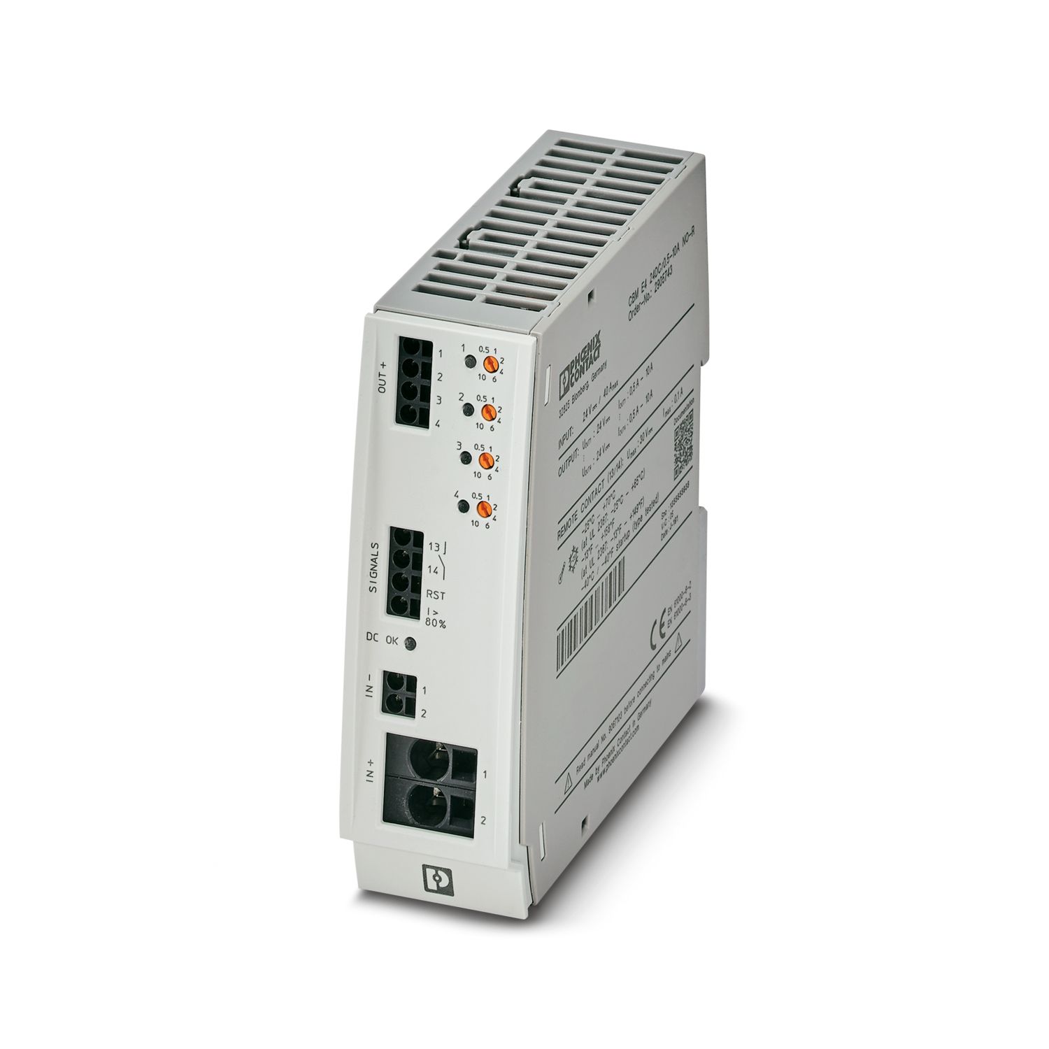
CBM E4 24DC/0.5-10A NO-R - Electronic circuit breaker 2905743
-
CBM E8 24DC/0.5-10A NO-R - Electronic circuit breaker 2905744
-
CAPAROC E4 12-24DC/1-10A - Electronic circuit breaker 1115658
-
TMC 72D 20A - Miniature Circuit Breaker 1020074


Переваги
High power density and high efficiency with a compact design
Customized use through flexible panel mounting options
Robust and reliable due to integrated protective functions
Easy power increase with parallel connection with integrated O-ring diode
Smart diagnostics with comprehensive monitoring via LED signaling, CAN bus interface, and EOL (End Of Life) reminder