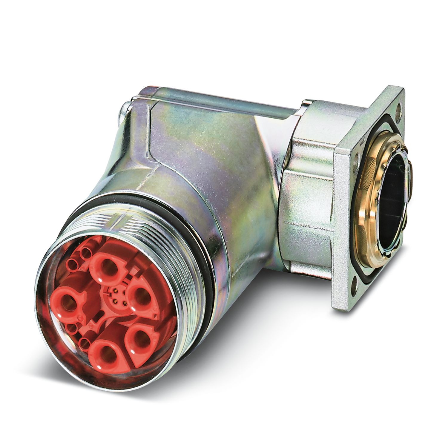
Device connector, front mounting - SB-8ESSA8AA700S
Pin version: dimension A = 3.7 mm, socket version: dimension A = 0.05 mm, X = reference position for angle of rotation
Installation dimensions
I = current strength, ϑ = ambient temperature, power contacts A–C: 3x up to 70 A, signal contacts: 4x 2 A constant, data contacts: no load
Device connector, front mounting - SB-8ESSA8AA700S
1623366
Device connector, front mounting, SB, angled rotatable, shielded: yes, for standard and SPEEDCON interlock, M40, Direction of rotation: Standard, type of contact: Socket, Crimp connection, Axial O-ring, 4x Ø4,2
Crimp contacts, 8 x Ø 1 mm, 5 x Ø 3.6 mm, order separately
Safety note
Safety note
WARNING: The connectors may not be plugged in or disconnected under load. Ignoring the warning or improper use may damage persons and/or property.
• WARNING: Commission properly functioning products only. The products must be regularly inspected for damage. Decommission defective products immediately. Replace damaged products. Repairs are not possible.
• WARNING: Only electrically qualified personnel may install and operate the product. They must observe the following safety notes. The qualified personnel must be familiar with the basics of electrical engineering. They must be able to recognize and prevent danger. The relevant symbol on the packaging indicates that only personnel familiar with electrical engineering are allowed to install and operate the product.
• The products are suitable for applications in plant, controller, and electrical device engineering.
• When operating the connectors in outdoor applications, they must be separately protected against environmental influences.
• Assembled products may not be manipulated or improperly opened.
• Only use mating connectors that are specified in the technical data of the standards listed (e.g. the ones listed in the product accessories online at phoenixcontact.com/products).
• When using the product in direct connection with third-party manufacturers, the user is responsible.
• For operating voltages > 50 V AC, conductive connector housings must be grounded
• VDE 0100/1.97 § 411.1.3.2 and DIN EN 60 204/11.98 § 14.1.3 are applicable when combining several circuits in a cable and/or connector
• Observe the corresponding technical data. You will find information: o On the product o On the packing label o In the supplied documentation o Online at phoenixcontact.com/products under the product
• Only use tools recommended by Phoenix Contact
• The installation notes/Design In documents online on the download page at phoenixcontact.com/products must be observed for this product.
• Use a protective cap to protect connectors that are not in use. The suitable accessories are available online in the accessory section of the product at phoenixcontact.com/products
• Operate the connector only when it is fully plugged in and interlocked.
• Ensure that when laying the cable, the tensile load on the connectors does not exceed the upper limit specified in the standards.
• Observe the minimum bending radius of the cable. Lay the cable without twisting it.
• The connector warms up in normal operation. Depending on the ambient conditions, the surface of the connector can continue to warm up. In this case, the user is responsible for posting warnings (e.g. DIN EN ISO 13732-1:2008-12).