
The fourth generation of the high-performance QUINT POWER power supplies ensures superior system availability by means of new functions. Signaling thresholds and characteristic curves can be individually adjusted via the NFC interface.
The unique SFB technology and preventive function monitoring of the QUINT POWER power supply increase the availability of your application.
QUINT4-PS/3AC/48DC/20
-
Power supply
2904627
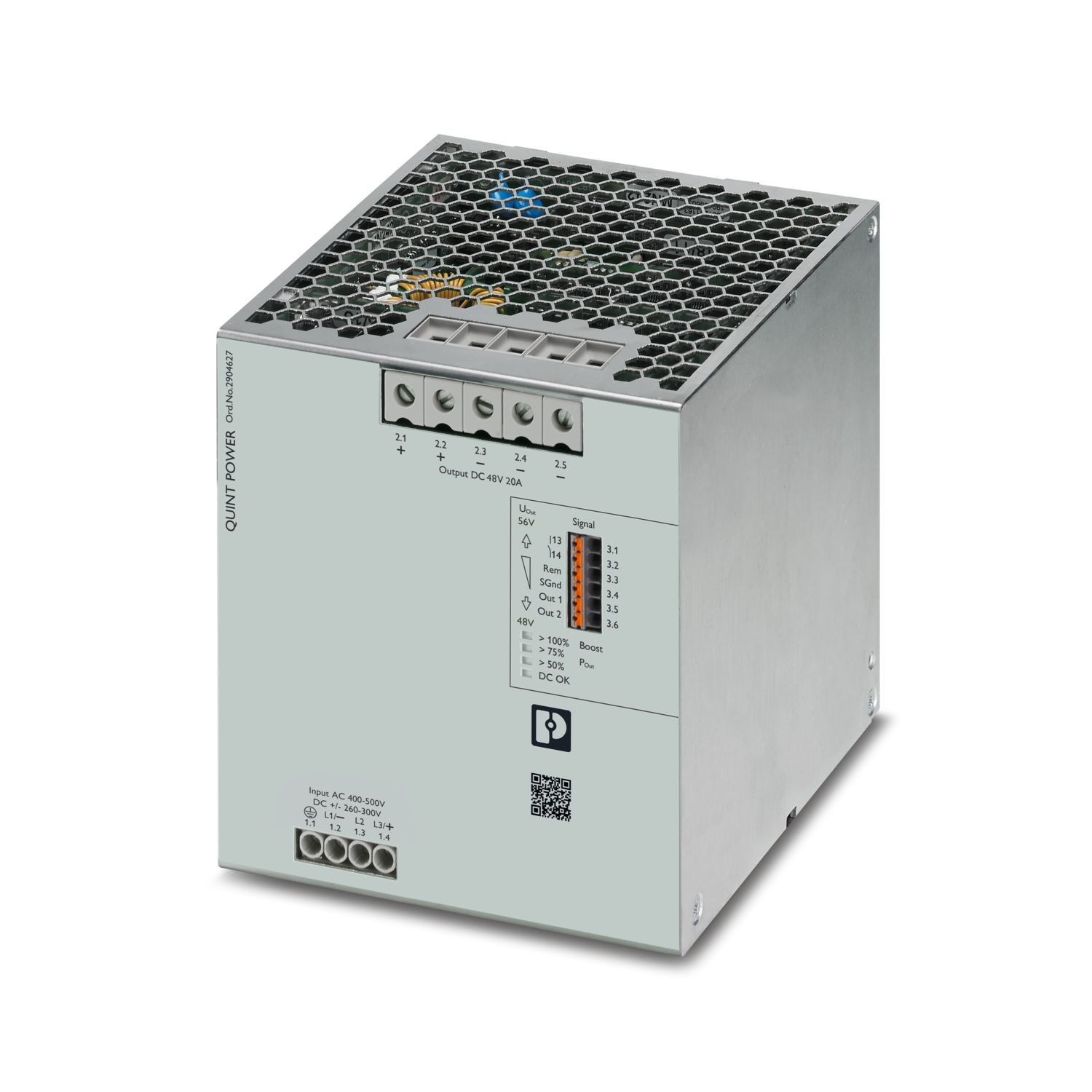

QUINT POWER primary-switched power supply with free choice of output characteristic curve, SFB (Selective Fuse Breaking) Technology, and NFC interface, input: 3-phase, output: 48 V DC/20 A
Transferência gratuita disponível.
Downloads
Detalhes dos produtos
LR
ID de certificação: LR22472797TAcULus Listed
ID de certificação: E123528-20210917cCSAus
ID de certificação: 800097463BV
ID de certificação: 44621/B1 BVSEMI F47
ID de certificação: SEMI F47ABS
ID de certificação: 26-0442641-PDAcULus Listed
ID de certificação: E199827-2021-10-22


Vantagens
SFB Technology selectively trips standard miniature circuit breakers
Preventive function monitoring indicates critical operating states before errors occur
Power reserves for easy system extension and starting up difficult loads
High efficiency, long service life, and maximum immunity with integrated gas discharge tube
Available pre-configured: from a batch quantity of just 1
Perguntas mais frequentes
Can I trigger a standard miniature circuit breaker with the power supply?
Yes, standard miniature circuit breakers can be triggered safely with the QUINT power supply. Please refer to the SFB Technology section in the data sheet.
What power reserves are available?
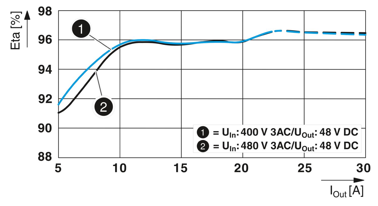
For system expansion purposes, the sustained static boost supports the load supply with 22.5 A. The static boost is available at an ambient temperature of up to 40°C.
The QUINT POWER power supply provides a dynamic boost of up to 30 A for reliable...
Ver mais
For system expansion purposes, the sustained static boost supports the load supply with 22.5 A. The static boost is available at an ambient temperature of up to 40°C.
The QUINT POWER power supply provides a dynamic boost of up to 30 A for reliable starting of heavy loads. This temporary power supply to the load lasts a maximum of 5 s at an ambient temperature of up to 60°C
Can the input voltage of the power supply be monitored?
Yes, the “Input voltage OK” signal option can be used to signal a failure of the input voltage at an early stage. In the event of a mains failure, the power supply continues to supply the load for at least 26 ms. Failure of the input voltage is signa... Ver mais
Yes, the “Input voltage OK” signal option can be used to signal a failure of the input voltage at an early stage. In the event of a mains failure, the power supply continues to supply the load for at least 26 ms. Failure of the input voltage is signaled 10 ms before the output voltage falls, which means that this information is provided to the higher-level controller at an early stage.
Ver menosCan the temperature of the power supply be monitored?
Yes, with the “Temperature OK” signal option, an elevated temperature can be signaled even before the QUINT POWER power supply is protected by the power derating.
How can the signal contacts be customized?
The signal contacts can be preset directly when ordering the QUINT POWER power supply via the configurator. Alternatively, the power supply can also be configured at a later time via the QUINT POWER software or QUINT POWER app.
How can the output voltage of the power supply be customized?
The QUINT POWER power supply can be ordered directly with a preset output voltage. Alternatively, the voltage can be set using the buttons on the front or via the QUINT POWER software or QUINT POWER app.
Can the buttons for voltage setting also be disabled?
Yes, the buttons on the front can be locked using the QUINT POWER software or QUINT POWER app.