
The fourth generation of the high-performance QUINT POWER power supplies ensures superior system availability by means of new functions. Signaling thresholds and characteristic curves can be individually adjusted via the NFC interface.
The unique SFB technology and preventive function monitoring of the QUINT POWER power supply increase the availability of your application.
QUINT4-PS/3AC/24DC/40/VASS
-
Power supply
1168603
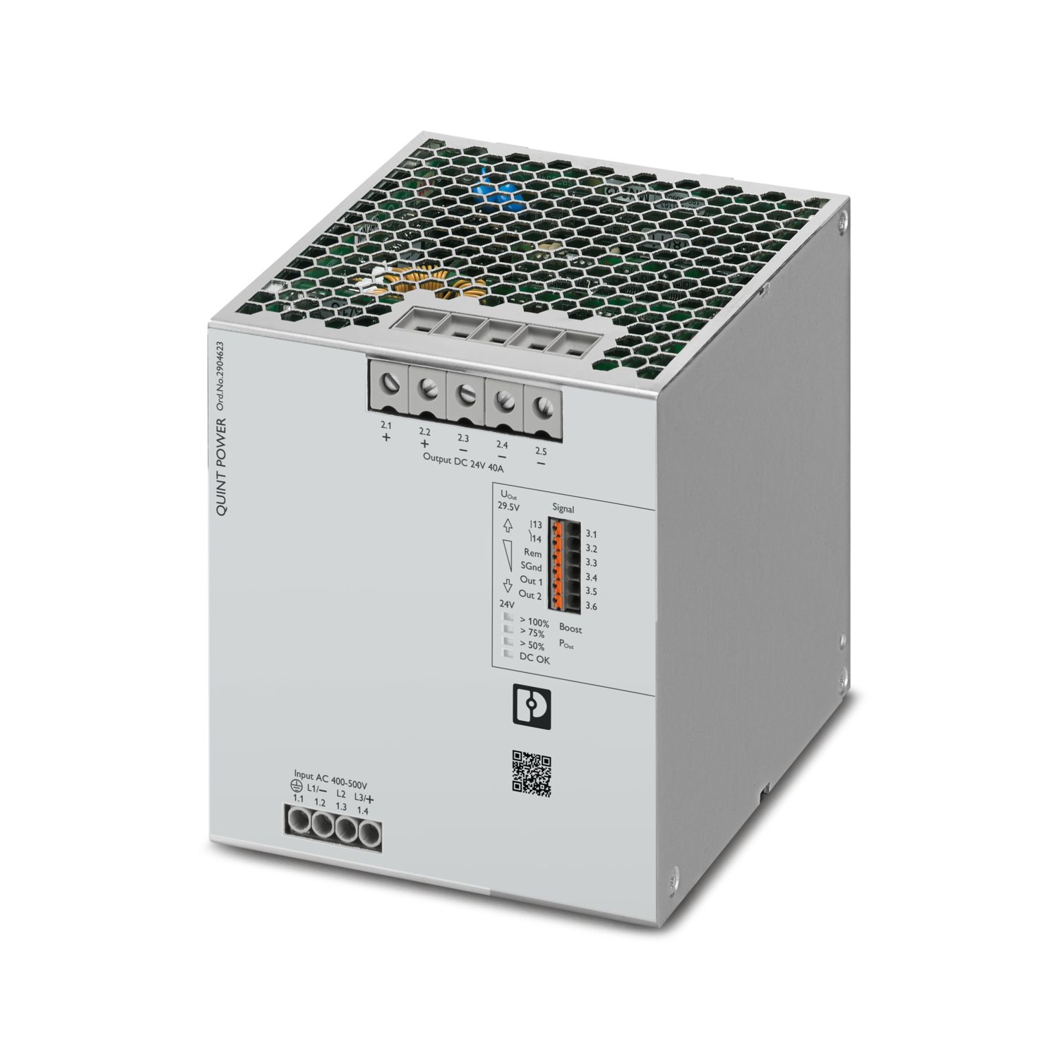

Preconfigured and read-only version of the primary-switched QUINT POWER power supply with set output voltage and adjusted signaling, input: 3-phase, output: 24 V DC/40 A. Product is being prepared for compliance with the Cyber Resilience Act (CRA).
Transferência gratuita disponível.
Downloads
Detalhes dos produtos
| Note on application | |
| Note on application | As things stand now, we are preparing the product so that, as of December 11, 2027, it will comply with the requirements of the EU Cyber Resilience Act (CRA) based on the information currently available regarding the CRA. |
| Control input (configurable) Rem | Output power ON/OFF (SLEEP MODE) |
| Default | Output power ON (>40 kΩ/24 V DC/open bridge between Rem and SGnd) |
| AC operation | |
| Network type | Star network |
| Nominal input voltage range | 3x 400 V AC ... 500 V AC |
| 2x 400 V AC ... 500 V AC | |
| Input voltage range | 3x 400 V AC ... 500 V AC -20 % ... +10 % |
| 2x 400 V AC ... 500 V AC -10 % ... +10 % | |
| Typical national grid voltage | 400 V AC |
| 480 V AC | |
| Voltage type of supply voltage | AC |
| Inrush current | typ. 1.5 A (at 25 °C) |
| Inrush current integral (I2t) | < 0.06 A2s |
| Inrush current limitation | 0 A (after 1 ms) |
| Frequency range (fN) | 50 Hz ... 60 Hz -10 % ... +10 % |
| Mains buffering time | typ. 28 ms (3x 400 V AC) |
| typ. 28 ms (3x 480 V AC) | |
| Current consumption | 3x 1.8 A (400 V AC) |
| 3x 1.5 A (480 V AC) | |
| 2x 3 A (400 V AC) | |
| 2x 2.5 A (480 V AC) | |
| 3x 1.5 A (500 V AC) | |
| 2x 2.4 A (500 V AC) | |
| Nominal power consumption | 1217 VA |
| Protective circuit | Transient surge protection; Varistor, gas-filled surge arrester |
| Power factor | 0.91 |
| Switch-on time | < 1 s |
| Typical response time | 300 ms (from SLEEP MODE) |
| Recommended breaker for input protection | 3x 4 A ... 20 A (Characteristic B, C, D, K or comparable) |
| Recommended fuse for input protection | ≥ 300 V AC |
| Discharge current to PE | < 3.5 mA |
| 1 mA (550 V AC, 60 Hz) | |
| DC operation | |
| Nominal input voltage range | ± 260 V DC ... 300 V DC |
| Input voltage range | ± 260 V DC ... 300 V DC -13 % ... +30 % |
| Voltage type of supply voltage | DC |
| Current consumption | 2.2 A (±260 V DC) |
| 1.9 A (±300 V DC) | |
| Nominal power consumption | 1217 VA |
| Recommended breaker for input protection | 1x 6 A (10 x 38 mm, 30 kA L/R = 2 ms) |
| Recommended fuse for input protection | ≥ 1000 V DC |
| Efficiency | typ. 95.7 % (400 V AC) |
| typ. 95.7 % (480 V AC) | |
| Nominal output voltage | 26 V DC |
| Setting range of the output voltage (USet) | 24 V DC ... 29.5 V DC (constant capacity) |
| Nominal output current (IN) | 40 A |
| Static Boost (IStat.Boost) | 45 A |
| Dynamic Boost (IDyn.Boost) | 60 A (5 s) |
| Selective Fuse Breaking (ISFB) | 215 A (15 ms) |
| Magnetic circuit breaker tripping | A1...A40 / B2...B25 / C1...C13 / Z1...Z16 |
| Feedback voltage resistance | ≤ 35 V DC |
| Protection against overvoltage at the output (OVP) | ≤ 32 V DC |
| Control deviation | < 0.5 % (Static load change 10 % ... 90 %) |
| < 3 % (Dynamic load change 10 % ... 90 %, (10 Hz)) | |
| < 0.25 % (change in input voltage ±10 %) | |
| Residual ripple | < 50 mVPP (with nominal values) |
| Short-circuit-proof | yes |
| No-load proof | yes |
| Output power | 960 W |
| 1080 W | |
| 1440 W | |
| Maximum no-load power dissipation | < 5 W (400 V AC) |
| < 5 W (480 V AC) | |
| Power loss nominal load max. | < 45 W (400 V AC) |
| < 45 W (480 V AC) | |
| Power dissipation SLEEP MODE | < 2 W (400 V AC) |
| < 2 W (480 V AC) | |
| Crest factor | typ. 1.6 (400 V AC) |
| typ. 1.9 (480 V AC) | |
| Rise time | < 1 s (UOut = 10 % ... 90 %) |
| Connection in parallel | yes, for redundancy and increased capacity |
| Connection in series | yes |
| Signal | |
| Signal ground SGnd | Reference potential for Out1, Out2, and Rem |
| Signal Out 1 (configurable) | |
| Digital | 24 V DC 20 mA |
| Default | 24 V DC 20 mA 24 V DC for UOut > 0.9 x USet |
| Signal Out 2 (configurable) | |
| Digital | 24 V DC 20 mA |
| Analog | 4 mA ... 20 mA ±5 % (Load ≤400 Ω) |
| Default | 24 V DC 20 mA 24 V DC for 3AC OK (phase monitoring) |
| Signal relay 13/14 (configurable) | |
| Default | closed (UOut >0.9 x Uset and POut <0.9 x PN) |
| Digital | 24 V DC 1 A |
| 30 V AC/DC 0.5 A | |
| Input | |
| Connection method | Screw connection |
| Conductor cross-section, rigid min. | 0.2 mm² |
| Conductor cross-section, rigid max. | 6 mm² |
| Conductor cross-section flexible min. | 0.2 mm² |
| Conductor cross-section flexible max. | 4 mm² |
| Single conductor/flexible terminal point with ferrule with plastic sleeve, min. | 0.25 mm² |
| Single conductor/flexible terminal point with ferrule with plastic sleeve, max. | 4 mm² |
| Single conductor/flexible terminal point with ferrule without plastic sleeve, min. | 0.25 mm² |
| Single conductor/flexible terminal point with ferrule without plastic sleeve, max. | 4 mm² |
| Conductor cross-section AWG min. | 24 |
| Conductor cross-section AWG max. | 10 |
| Stripping length | 8 mm |
| Tightening torque, min | 0.5 Nm |
| Tightening torque max | 0.6 Nm |
| Output | |
| Connection method | Screw connection |
| Conductor cross-section, rigid min. | 0.5 mm² |
| Conductor cross-section, rigid max. | 16 mm² |
| Conductor cross-section flexible min. | 0.5 mm² |
| Conductor cross-section flexible max. | 16 mm² |
| Single conductor/flexible terminal point with ferrule with plastic sleeve, min. | 0.5 mm² |
| Single conductor/flexible terminal point with ferrule with plastic sleeve, max. | 16 mm² |
| Single conductor/flexible terminal point with ferrule without plastic sleeve, min. | 0.5 mm² |
| Single conductor/flexible terminal point with ferrule without plastic sleeve, max. | 16 mm² |
| Conductor cross-section AWG min. | 20 |
| Conductor cross-section AWG max. | 6 |
| Stripping length | 10 mm |
| Tightening torque, min | 1.2 Nm |
| Tightening torque max | 1.5 Nm |
| Signal | |
| Connection method | Push-in connection |
| Conductor cross-section, rigid min. | 0.2 mm² |
| Conductor cross-section, rigid max. | 1 mm² |
| Conductor cross-section flexible min. | 0.2 mm² |
| Conductor cross-section flexible max. | 1.5 mm² |
| Single conductor/flexible terminal point with ferrule with plastic sleeve, min. | 0.2 mm² |
| Single conductor/flexible terminal point with ferrule with plastic sleeve, max. | 0.75 mm² |
| Single conductor/flexible terminal point with ferrule without plastic sleeve, min. | 0.2 mm² |
| Single conductor/flexible terminal point with ferrule without plastic sleeve, max. | 1.5 mm² |
| Conductor cross-section AWG min. | 24 |
| Conductor cross-section AWG max. | 16 |
| Stripping length | 8 mm |
| Signal output | |
| POut | > 100 % (LED lights up yellow, output power > 960 W) |
| > 75 % (LED lights up green, output power > 720 W) | |
| > 50 % (LED lights up green, output power > 480 W) | |
| UOut | > 0.9 x USet (LED lights up green) |
| < 0.9 x USet (LED flashes green) | |
| Number of phases | 3 |
| Insulation voltage input/output | 4 kV AC (type test) |
| 2.4 kV AC (routine test) | |
| Insulation voltage output / PE | 0.5 kV DC (type test) |
| 0.5 kV DC (routine test) | |
| Insulation voltage input / PE | 3.5 kV AC (type test) |
| 2.4 kV AC (routine test) | |
| Switching frequency | 32.00 kHz ... 100.00 kHz (Auxiliary converter stage) |
| 55.00 kHz ... 300.00 kHz (Main converter stage) | |
| 25.00 kHz ... 500.00 kHz (PFC stage) |
| Product type | Power supply |
| Product family | QUINT POWER |
| MTBF (IEC 61709, SN 29500) | > 849000 h (25 °C) |
| > 517000 h (40 °C) | |
| > 236000 h (60 °C) | |
| Environmental protection directive | RoHS Directive 2011/65/EU |
| WEEE | |
| Reach | |
| Insulation characteristics | |
| Protection class | I |
| Overvoltage category (EN 60950-1) | II (≤ 5000 m) |
| Overvoltage category (EN 61010-1) | II (≤ 5000 m) |
| Overvoltage category (EN 62477-1) | III (≤ 2000 m) |
| Degree of pollution | 2 |
| Life expectancy (electrolytic capacitors) | |
| Current | 20 A |
| Temperature | 40 °C |
| Time | 394000 h |
| Additional text | 400 V AC |
| Life expectancy (electrolytic capacitors) | |
| Current | 20 A |
| Temperature | 40 °C |
| Time | 367000 h |
| Additional text | 480 V AC |
| Life expectancy (electrolytic capacitors) | |
| Current | 40 A |
| Temperature | 25 °C |
| Time | 394000 h |
| Additional text | 400 V AC |
| Life expectancy (electrolytic capacitors) | |
| Current | 40 A |
| Temperature | 25 °C |
| Time | 367000 h |
| Additional text | 480 V AC |
| Life expectancy (electrolytic capacitors) | |
| Current | 40 A |
| Temperature | 40 °C |
| Time | 139000 h |
| Additional text | 400 V AC |
| Life expectancy (electrolytic capacitors) | |
| Current | 40 A |
| Temperature | 40 °C |
| Time | 130000 h |
| Additional text | 480 V AC |
| Width | 120 mm |
| Height | 130 mm |
| Depth | 125 mm |
| Mounting type | DIN rail mounting |
| Mounting position | horizontal DIN rail NS 35, EN 60715 |
| With protective coating | no |
| Flammability rating according to UL 94 (housing / terminal blocks) | V0 |
| Housing material | Metal |
| Hood version | Stainless steel X6Cr17 |
| Side element version | Aluminum |
| Ambient conditions | |
| Degree of protection | IP20 |
| Ambient temperature (operation) | -25 °C ... 70 °C (> 60 °C Derating: 2,5 %/K) |
| Ambient temperature (storage/transport) | -40 °C ... 85 °C |
| Ambient temperature (start-up type tested) | -40 °C |
| Maximum altitude | ≤ 5000 m (> 2000 m, observe derating) |
| Climatic class | 3K3 (in acc. with EN 60721) |
| Max. permissible relative humidity (operation) | ≤ 95 % (at 25 °C, non-condensing) |
| Shock | 11 ms, 15 g, in each space direction (according to IEC 60068-2-27) |
| Vibration (operation) | 5 Hz ... 100 Hz resonance search 0.7g, 90 min., resonance frequency 0.7g, 90 min. (in accordance with DNV GL Class A) |
| Rail applications | EN 50121-5 |
| IEC 62236-5 | |
| HART FSK Physical Layer Test Specification Compliance | Output voltage UOut compliant |
| Standard – Electronic equipment for use in electrical power installations and their assembly into electrical power installations | EN 50178/VDE 0160 (PELV) |
| Standard – Limitation of mains harmonic currents | EN 61000-3-2 |
| Standard - Electrical safety | IEC 60950-1/VDE 0805 (SELV) |
| Standard – Safety extra-low voltage | IEC 60950-1 (SELV) |
| EN 60204-1 (PELV) | |
| Standard - safety for equipment for measurement, control, and laboratory use | IEC 61010-1 |
| Standard - Safety of transformers | EN 61558-2-16 |
| Approval - requirement of the semiconductor industry with regard to mains voltage dips | SEMI F47-0706, EN 61000-4-11 |
| CSA | CAN/CSA-C22.2 No. 60950-1-07 |
| CSA-C22.2 No. 107.1-01 | |
| Shipbuilding approval | DNV GL applied for |
| SIQ | BG (type approved) |
| UL approvals | UL Listed UL 508 |
| UL/C-UL Recognized UL 60950-1 | |
| UL ANSI/ISA-12.12.01 Class I, Division 2, Groups A, B, C, D (Hazardous Location) applied for |
| Electromagnetic compatibility | Conformance with EMC Directive 2014/30/EU |
| Low Voltage Directive | Conformance with Low Voltage Directive 2014/35/EC |
| Interference emission | Interference emission in accordance with EN 61000-6-3 (residential and commercial) and EN 61000-6-4 (industrial) |
| EMC requirements for noise immunity | EN 61000-6-1 |
| EN 61000-6-2 | |
| EMC requirements, power plant | IEC 61850-3 |
| EN 61000-6-5 | |
| Conducted noise emission | |
| Standards/regulations | EN 55016 |
| EN 61000-6-3 (Class B) | |
| Noise emission | |
| Standards/regulations | Additional basic standard EN 61000-6-5 (immunity in switching devices), IEC/EN 61850-3 (power supply) |
| Noise emission | |
| Standards/regulations | EN 55016 |
| EN 61000-6-3 (Class B) | |
| DNV GL conducted noise emissions | |
| DNV | Class A |
| Additional text | Area power distribution |
| DNV GL noise radiation | |
| DNV | Class B |
| Additional text | Bridge and deck area |
| Harmonic currents | |
| Standards/regulations | EN 61000-3-2 |
| EN 61000-3-2 (Class A) | |
| Frequency range | 0 kHz ... 2 kHz |
| Flicker | |
| Standards/regulations | EN 61000-3-3 |
| EN 61000-3-3 | |
| Frequency range | 0 kHz ... 2 kHz |
| Electrostatic discharge | |
| Standards/regulations | EN 61000-4-2 |
| Electrostatic discharge | |
| Contact discharge | 8 kV (Test Level 4) |
| Discharge in air | 15 kV (Test Level 4) |
| Comments | Criterion A |
| Electromagnetic HF field | |
| Standards/regulations | EN 61000-4-3 |
| Electromagnetic HF field | |
| Frequency range | 80 MHz ... 1 GHz |
| Test field strength | 20 V/m (Test Level 3) |
| Frequency range | 1 GHz ... 6 GHz |
| Test field strength | 10 V/m (Test Level 3) |
| Frequency range | 1 GHz ... 6 GHz |
| Test field strength | 10 V/m (Test Level 3) |
| Comments | Criterion A |
| Fast transients (burst) | |
| Standards/regulations | EN 61000-4-4 |
| Fast transients (burst) | |
| Input | 4 kV (Test Level 4 - asymmetrical) |
| Output | 4 kV (Test Level 4 - asymmetrical) |
| Signal | 2 kV (Test Level 4 - asymmetrical) |
| Comments | Criterion A |
| Surge voltage load (surge) | |
| Standards/regulations | EN 61000-4-5 |
| Surge voltage load (surge) | |
| Input | 2 kV (Test Level 3 - symmetrical) |
| 6 kV (Test Level 4 - asymmetrical) | |
| Output | 1 kV (Test Level 3 - symmetrical) |
| 2 kV (Test Level 3 - asymmetrical) | |
| Signal | 1 kV (Test Level 2 - asymmetrical) |
| Comments | Criterion A |
| Conducted interference | |
| Standards/regulations | EN 61000-4-6 |
| Conducted interference | |
| Input/output/signal | asymmetrical |
| Frequency range | 0.15 MHz ... 80 MHz |
| Comments | Criterion A |
| Voltage | 10 V (Test Level 3) |
| Power frequency magnetic field | |
| Standards/regulations | EN 61000-4-8 |
| Frequency | 16.7 Hz |
| 50 Hz | |
| 60 Hz | |
| Test field strength | 100 A/m |
| Additional text | 60 s |
| Comments | Criterion A |
| Frequency | 50 Hz |
| 60 Hz | |
| Frequency range | 50 Hz ... 60 Hz |
| Test field strength | 1 kA/m |
| Additional text | 3 s |
| Frequency | 0 Hz |
| Test field strength | 300 A/m |
| Additional text | DC, 60 s |
| Voltage dips | |
| Standards/regulations | EN 61000-4-11 |
| Voltage | 400 V AC |
| Frequency | 50 Hz |
| Voltage dip | 70 % |
| Number of periods | 0.5 / 1 / 25 periods |
| Additional text | Test Level 2 |
| Comments | Criterion A: 0.5 / 1 period Criterion B: 25 periods |
| Voltage dip | 40 % |
| Number of periods | 5 / 10 / 50 periods |
| Additional text | Test Level 2 |
| Comments | Criterion B |
| Voltage dip | 0 % |
| Number of periods | 0,5 / 1 / 5 / 50 / 250 periods |
| Additional text | Test Level 2 |
| Comments | Criterion A: 0.5 / 1 period Criterion B: 5 / 50 / 250 periods |
| Pulse-shape magnetic field | |
| Standards/regulations | EN 61000-4-9 |
| Test field strength | 1000 A/m |
| Comments | Criterion A |
| Attenuated sinusoidal oscillations (ring wave) | |
| Standards/regulations | EN 61000-4-12 |
| Input | 2 kV (Test Level 4 - symmetrical) |
| 4 kV (Test Level 4 - asymmetrical) | |
| Comments | Criterion A |
| Asymmetrical conducted disturbance variables | |
| Standards/regulations | EN 61000-4-16 |
| Test level 1 | 15 Hz 150 Hz (Test Level 4) |
| Voltage | 30 V 3 V |
| Test level 2 | 150 Hz 1.5 kHz (Test Level 4) |
| Voltage | 3 V |
| Test level 3 | 1.5 kHz 15 kHz (Test Level 4) |
| Voltage | 3 V 30 V |
| Test level 4 | 15 kHz 150 kHz (Test Level 4) |
| Voltage | 30 V |
| Test level 5 | 16.7 Hz 50 Hz 60 Hz (Test Level 4) |
| Voltage | 30 V (Permanent) |
| Test level 6 | 16.7 Hz 50 Hz 60 Hz (Test Level 4) |
| Voltage | 300 V (1 s) |
| Comments | Criterion A |
| Attenuated oscillating wave | |
| Standards/regulations | EN 61000-4-18 |
| Input, output (test level 1) | 100 kHz 1 MHz (Test Level 3 - symmetrical) |
| Voltage | 1 kV |
| Input, output (test level 2) | 10 MHz |
| Voltage | 1 kV |
| Input, output (test level 3) | 100 kHz 1 MHz (Test Level 3 - asymmetrical) |
| Voltage | 2.5 kV |
| Signals (test level 1) | 100 kHz 1 MHz (Test Level 3 - symmetrical) |
| Voltage | 1 kV |
| Signals (test level 2) | 100 kHz 1 MHz (Test Level 3 - asymmetrical) |
| Voltage | 2.5 kV |
| Comments | Criterion A |
| Attenuated oscillating magnetic field | |
| Standards/regulations | EN 61000-4-10 |
| Test field strength | 110 A/m |
| Test level 1 | 100 kHz |
| Test field strength | 110 A/m |
| Test level 2 | 1 MHz |
| Comments | Criterion A |
| Criteria | |
| Criterion A | Normal operating behavior within the specified limits. |
| Criterion B | Temporary impairment to operational behavior that is corrected by the device itself. |
| Criterion C | Temporary adverse effects on the operating behavior, which the device corrects automatically or which can be restored by actuating the operating elements. |
| N.º de artigo | 1168603 |
| Pcs./Emb | 1 Unidade |
| Quantidade mínima de pedido | 1 Unidade |
| Observação | Produção ligada a pedido (sem devolução) |
| Chave comercial | CMP |
| Chave de produto | CMPI33 |
| GTIN | 4063151186913 |
| Peso por unidade (inclusive embalagem) | 2 756 g |
| Peso por unidade (excluindo embalagem) | 2 422 g |
| Número do imposto alfandegário | 85044095 |
| País de origem | TH |
ECLASS
| ECLASS-13.0 | 27040701 |
| ECLASS-15.0 | 27040701 |
ETIM
| ETIM 10.0 | EC002540 |
UNSPSC
| UNSPSC 21.0 | 39121000 |
UL Recognized
ID de certificação: E211944IECEE CB Scheme
ID de certificação: SI-7230EAC
ID de certificação: RU S-DE.BL08.W.00764IECEE CB Scheme
ID de certificação: SI-7268EAC
ID de certificação: RU S-DE.BL08.W.00764cCSAus
ID de certificação: 800097463cULus Listed
ID de certificação: 20190619-E123528EAC
ID de certificação: KZ7500651 0101 12535cULus Listed
ID de certificação: E199827-20191015| EU RoHS | |
| Cumpre os requisitos de substância segundo a Diretiva RoHS | Sim |
| isenções tanto quanto conhecido | 7(a), 7(c)-I |
| China RoHS | |
| Environment friendly use period (EFUP) |
EFUP-25
Uma lista de declaração de acordo com a RoHS da China relativa a artigos encontra-se na área de transferências do respetivo artigo, em "Declaração do fabricante". Para todos os artigos com EFUP-E não é emitida nem necessária uma tabela de declaração de acordo com a RoHS da China.
|
| EU REACH SVHC | |
| Nota sobre as substâncias candidatas ao REACH (n.º CAS) | Lead|7439-92-1 (n.º CAS: Não aplicável) |
| SCIP | e9c7c0cc-1b7f-43cb-8671-d70c01416dc9 |
| EF3.1 Alterações climáticas | |
| CO2e kg | 54,654 kg CO2e |
Produtos compatíveis
-
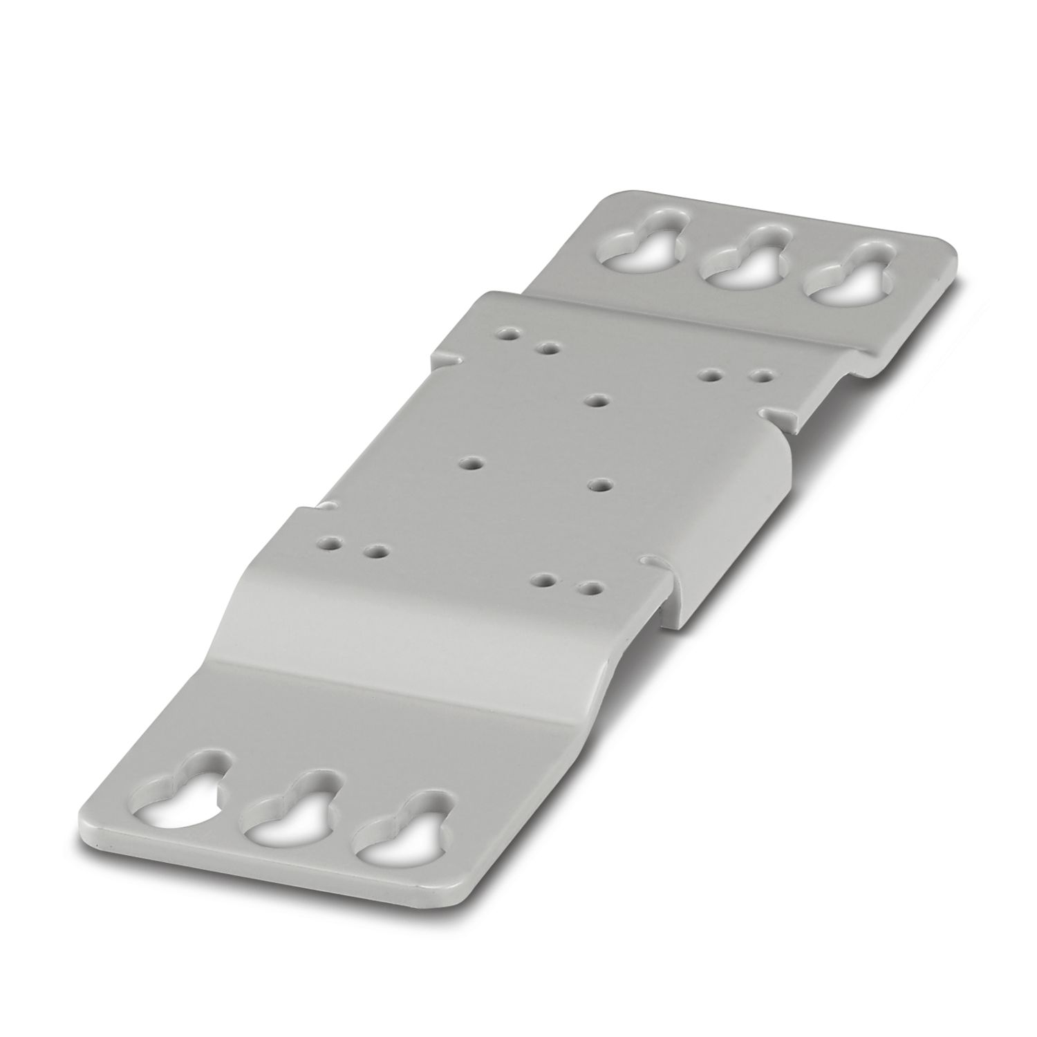
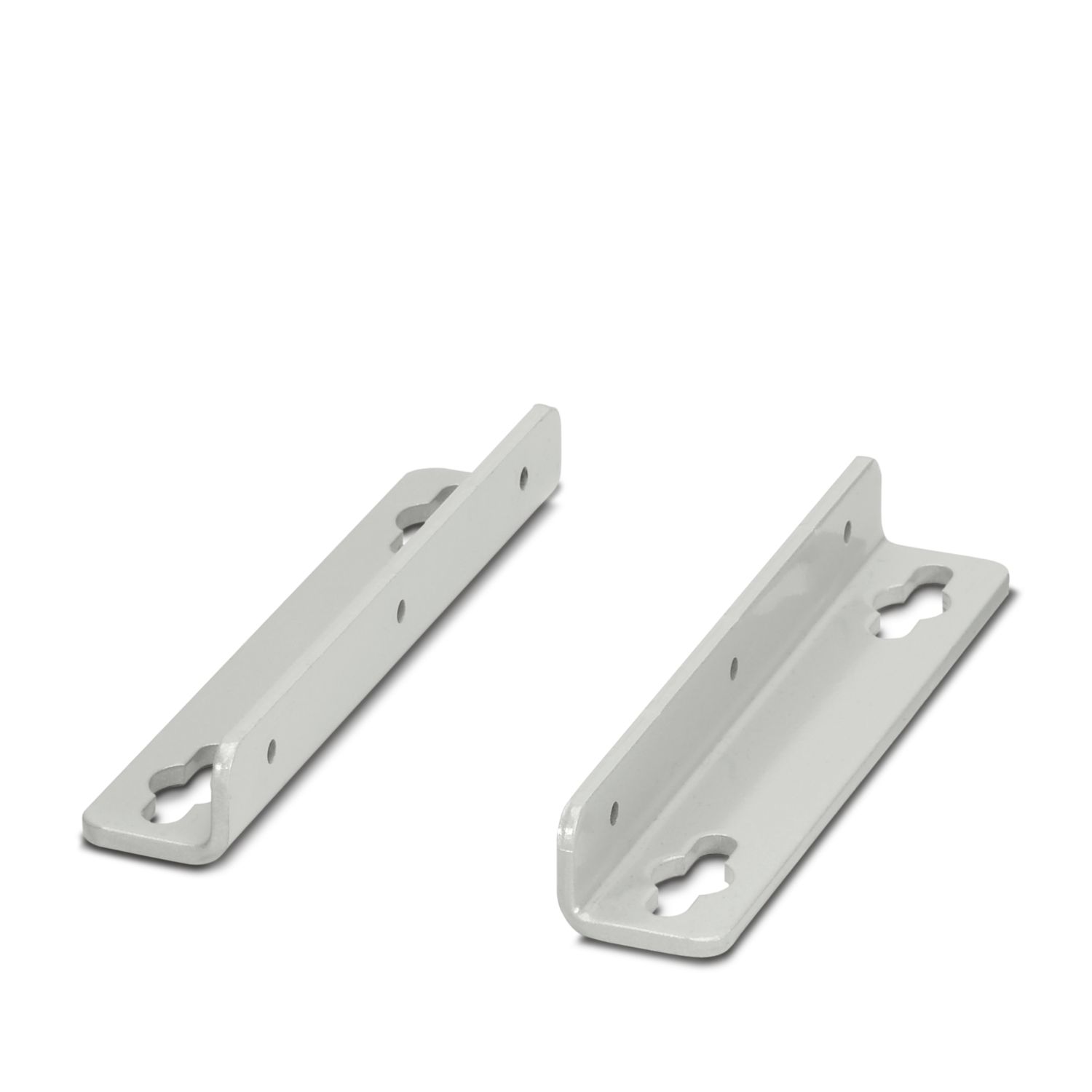
UWA 182/52 - Mounting adapter 2938235
-
UWA 130 - Mounting adapter 2901664
-
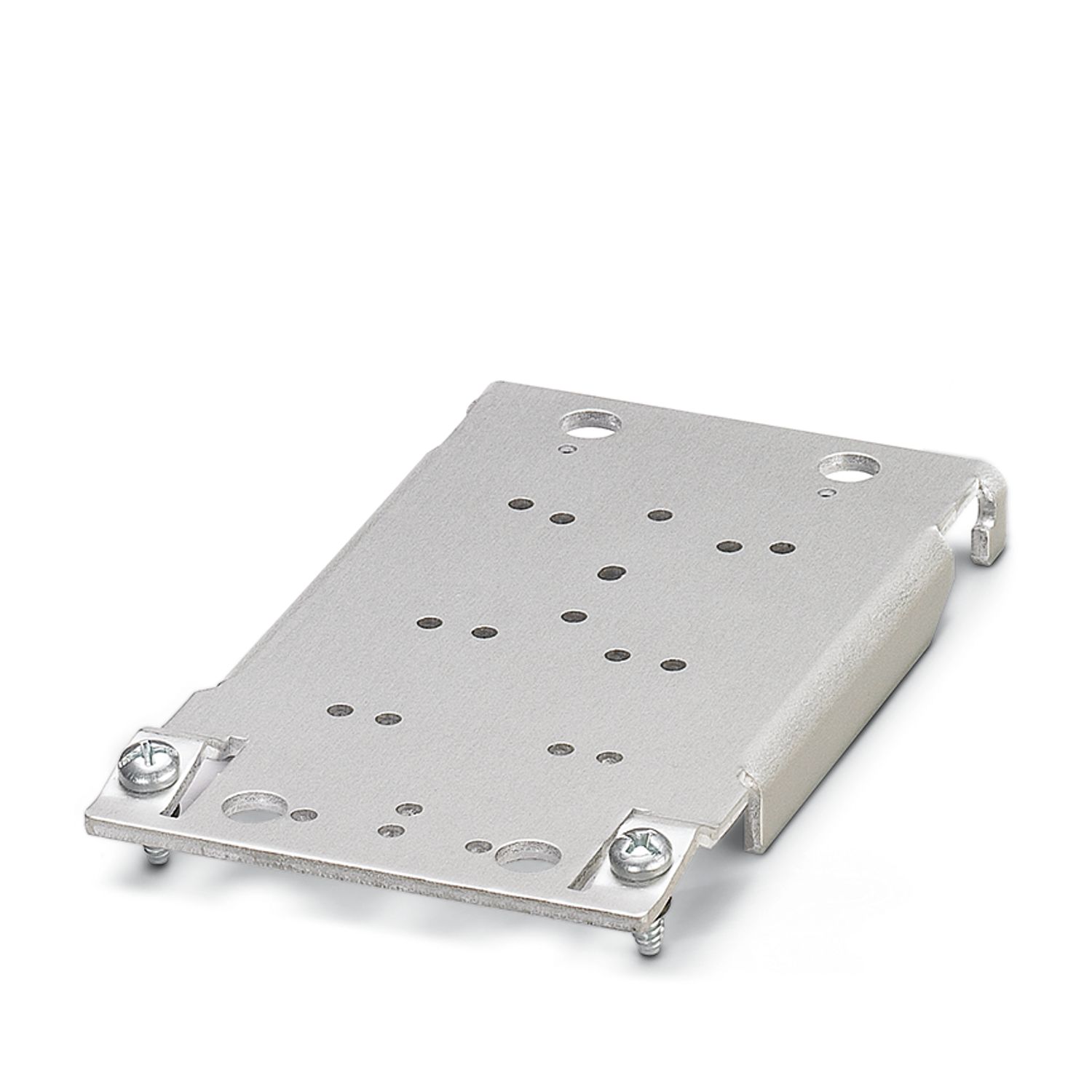
QUINT-PS-ADAPTERS7/1 - Mounting adapter 2938196
-
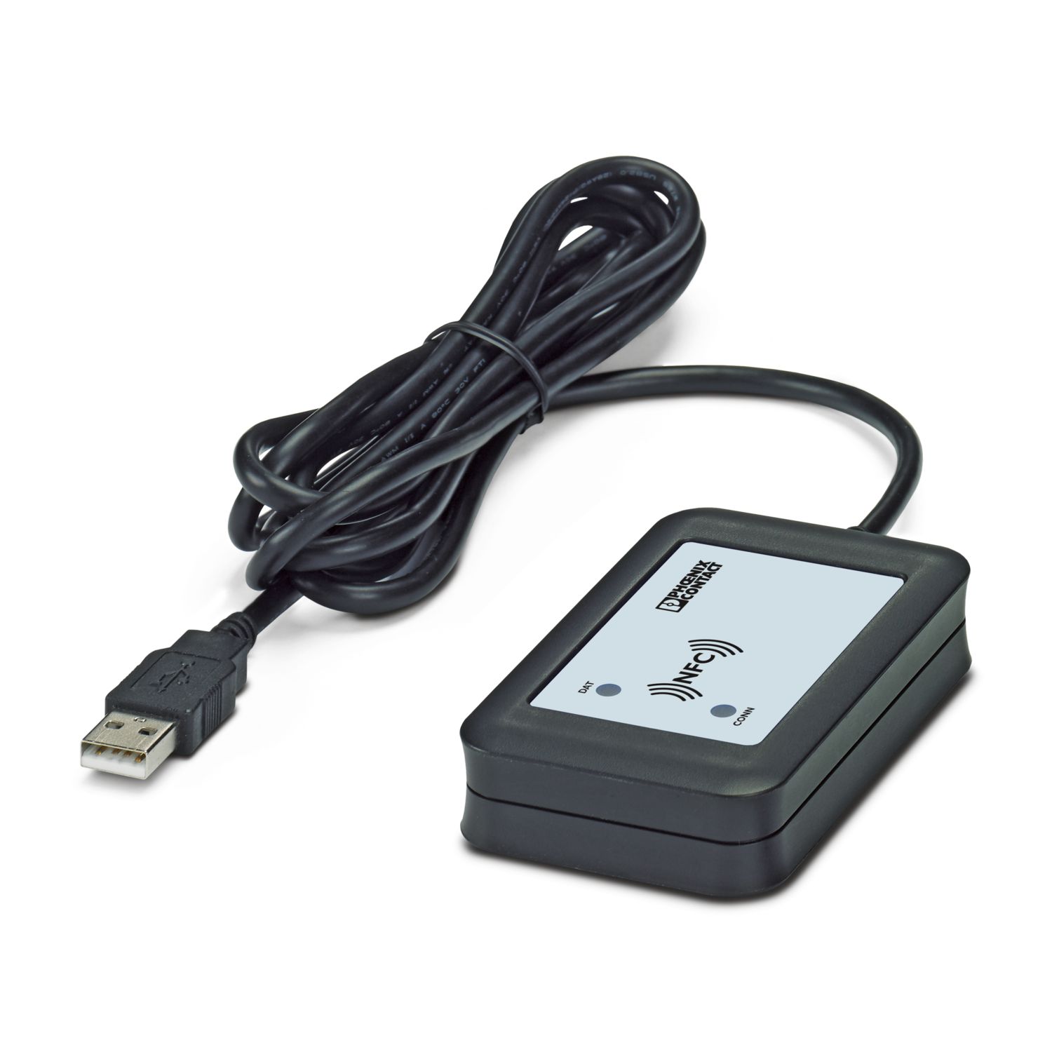
TWN4 MIFARE NFC USB ADAPTER - Programming adapter 2909681
-
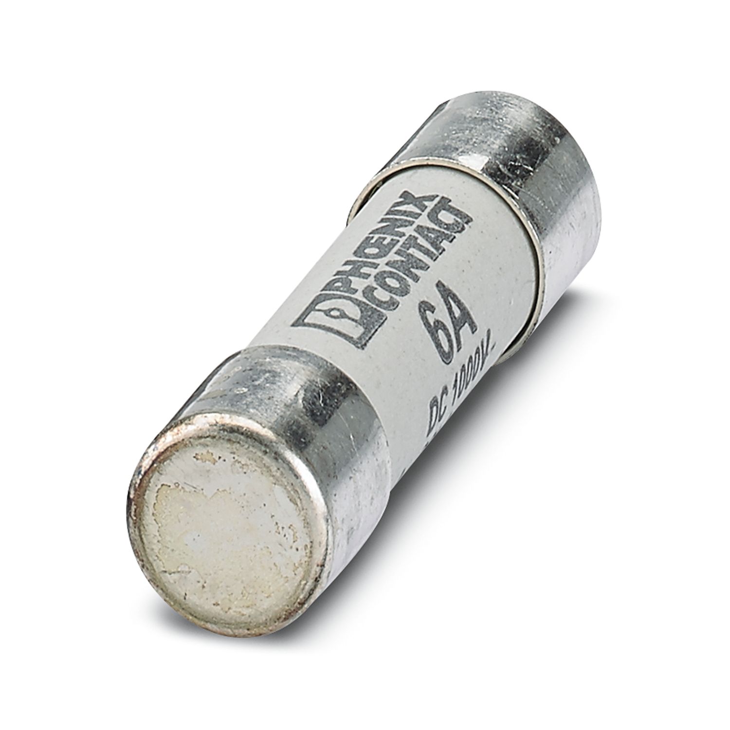
FUSE 10,3X38 6A PV A - Fuse 3062778
-
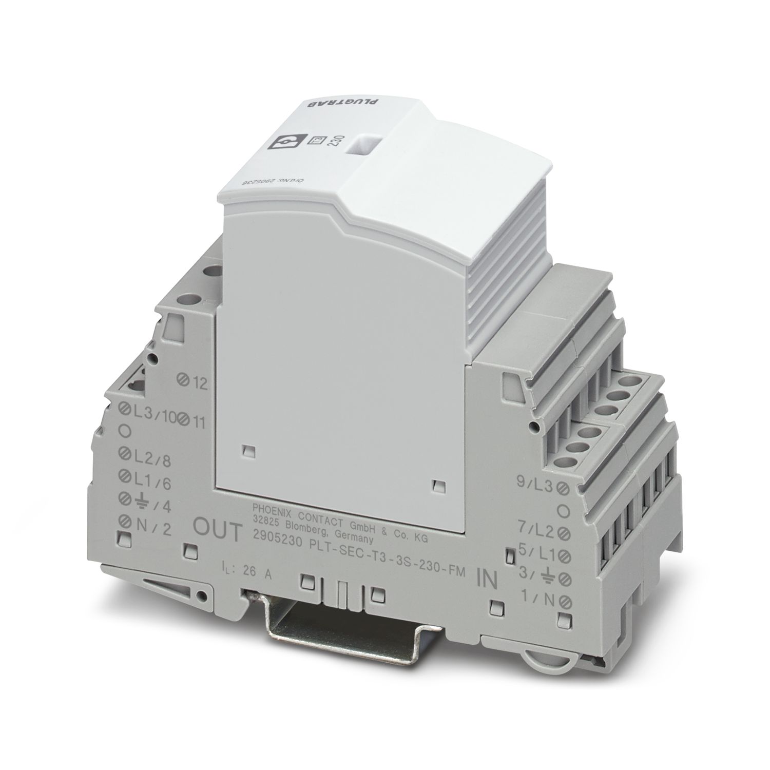
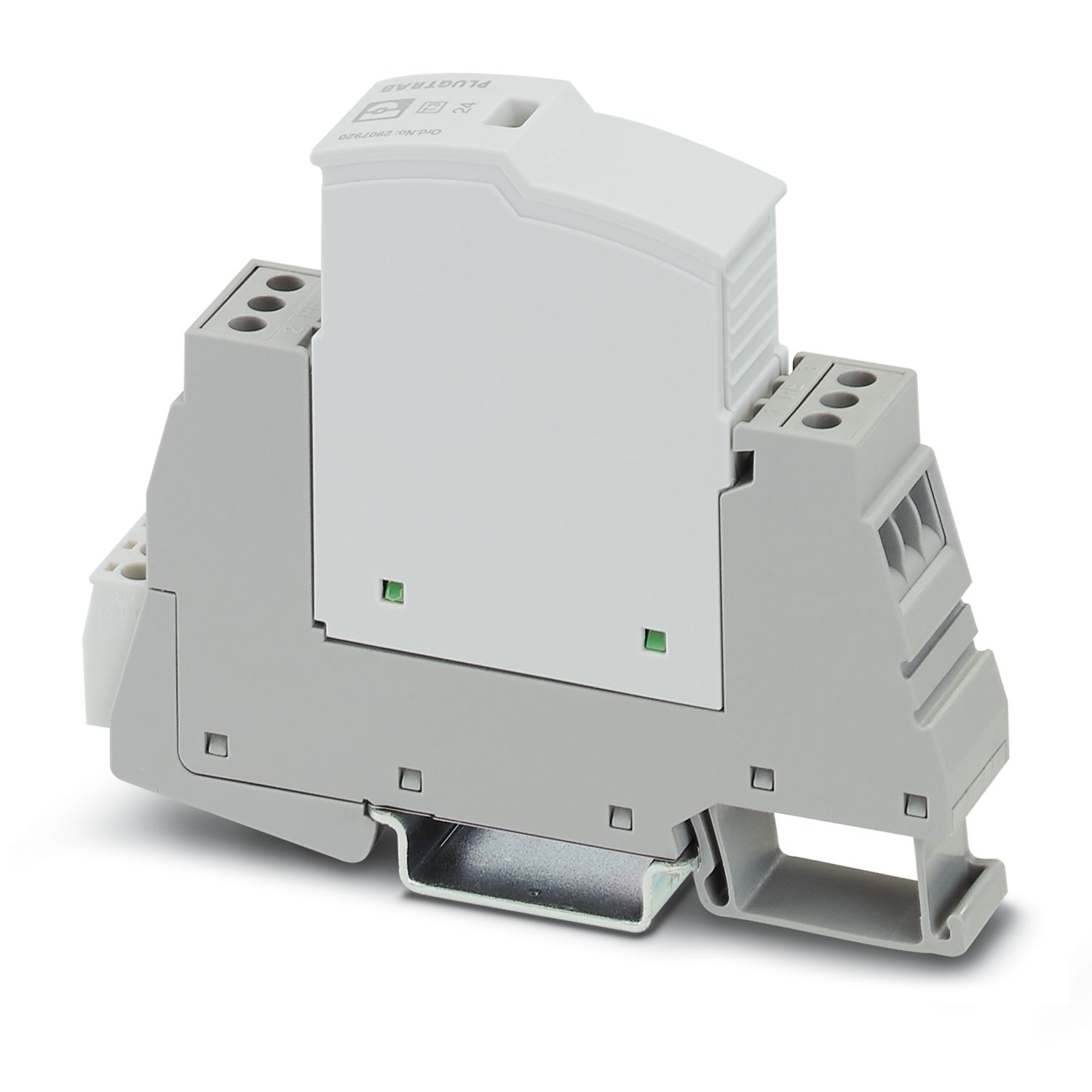
PLT-SEC-T3-3S-230-FM - Type 3 surge protection device 2905230
-
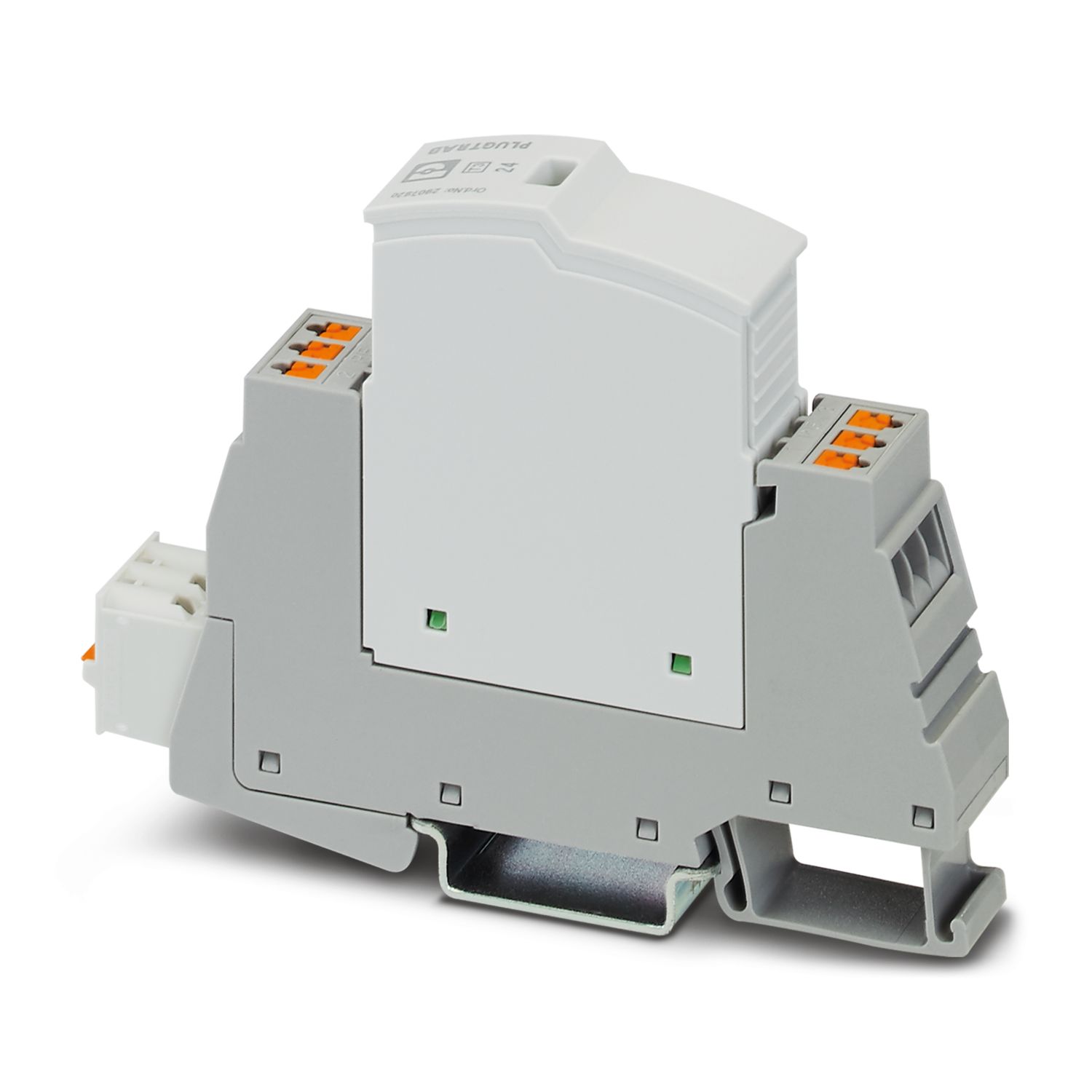
PLT-SEC-T3-24-FM-PT - Type 3 surge protection device 2907925
-
PLT-SEC-T3-24-FM-UT - Type 3 surge protection device 2907916
-
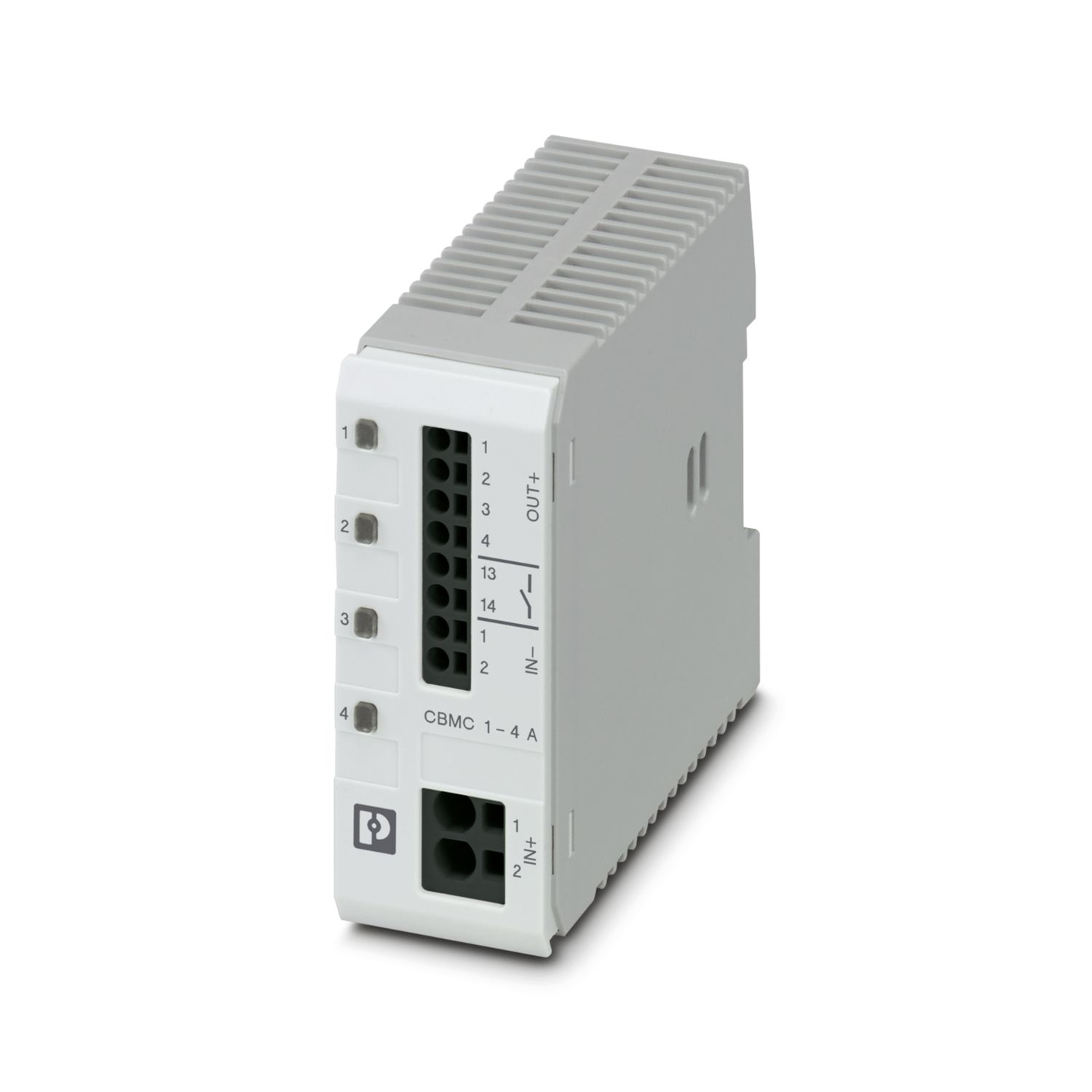
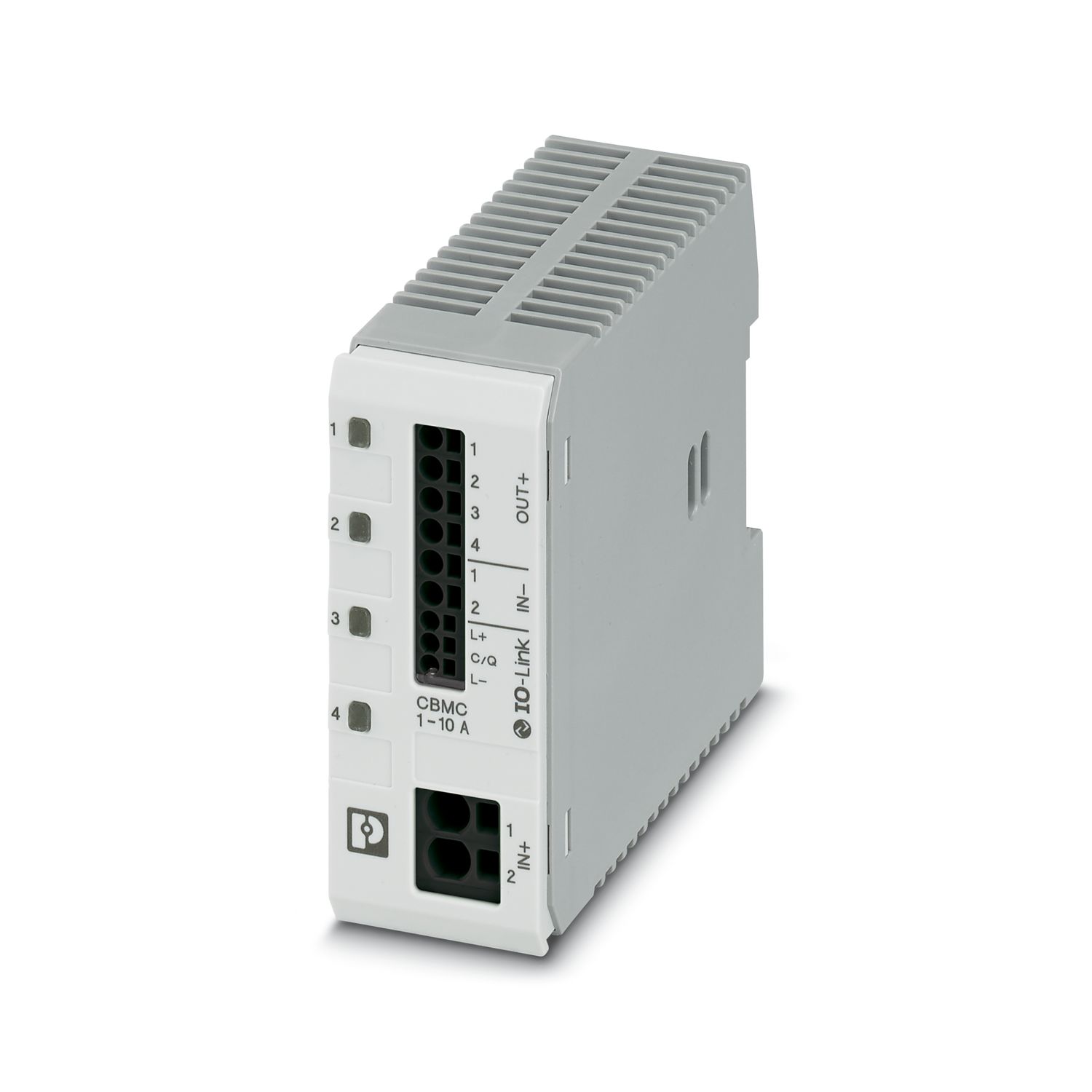
CBMC E4 24DC/1-4A NO - Electronic circuit breaker 2906031
-
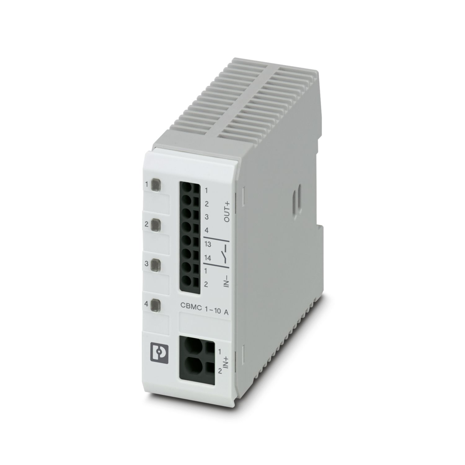
CBMC E4 24DC/1-10A NO - Electronic circuit breaker 2906032
-
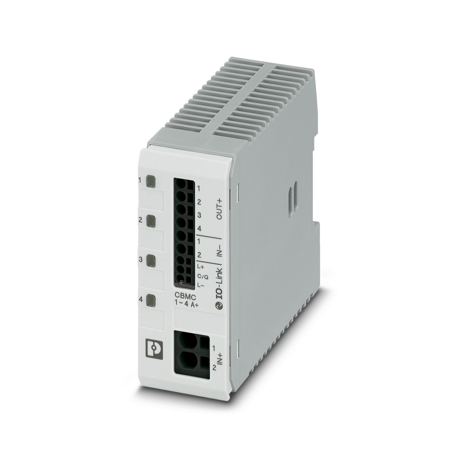
CBMC E4 24DC/1-4A+ IOL - Electronic circuit breaker 2910410
-
CBMC E4 24DC/1-10A IOL - Electronic circuit breaker 2910411
-
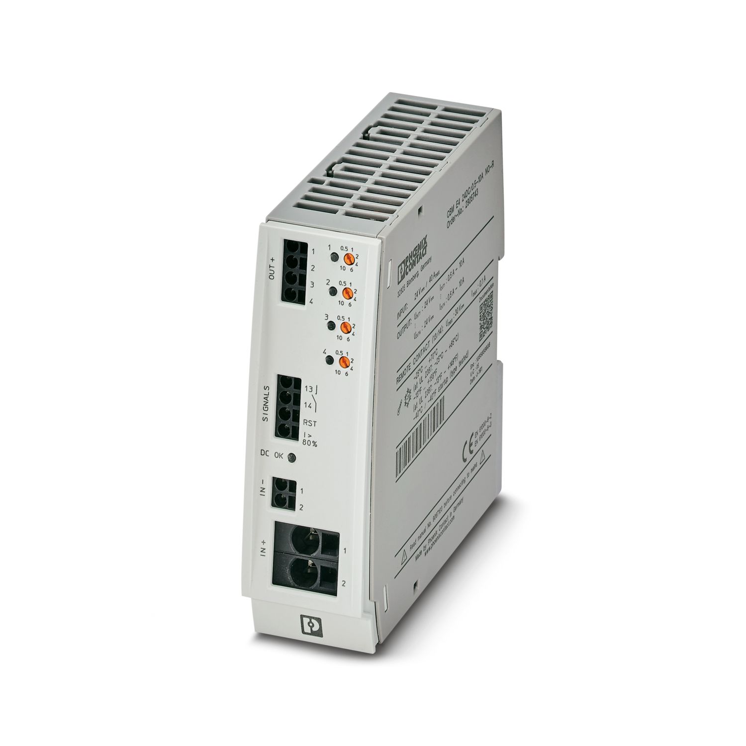
CBM E4 24DC/0.5-10A NO-R - Electronic circuit breaker 2905743
-
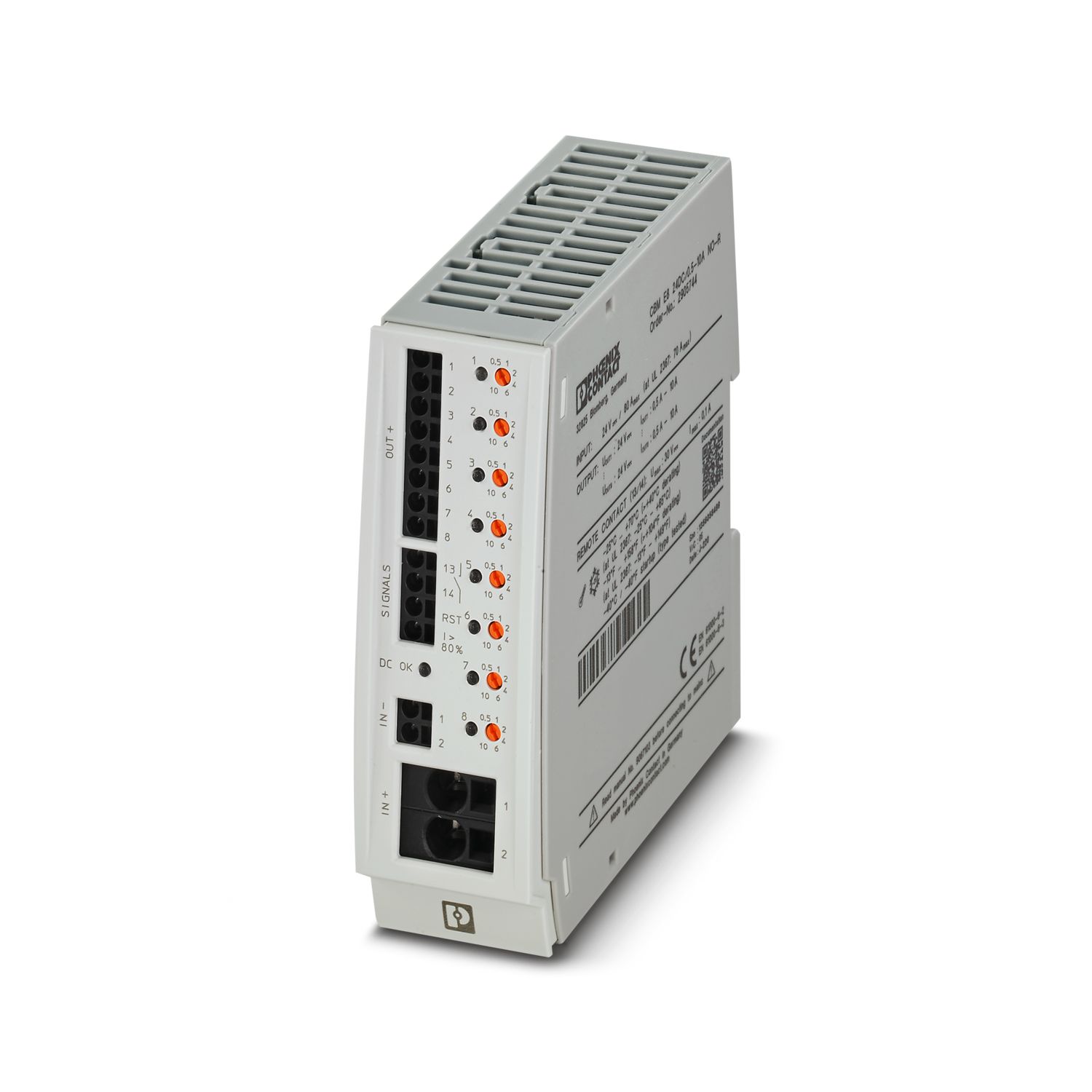
CBM E8 24DC/0.5-10A NO-R - Electronic circuit breaker 2905744
-
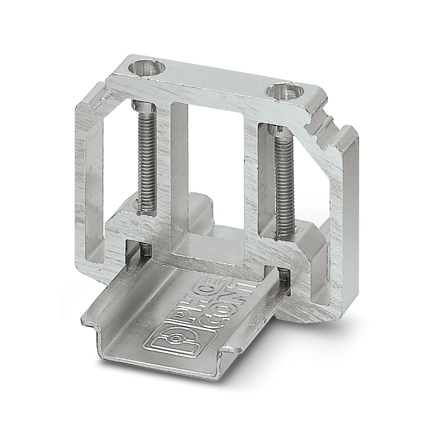
E/AL-NS 35 - End bracket 1201662
Vantagens
Most powerful output side: easy system expansion, reliable heavy load startup and miniature circuit breaker tripping
Most robust input side: high noise immunity, thanks to integrated gas-filled surge arrester (up to 6 kV) and ≥ 20 ms mains failure buffer time
Most comprehensive signaling: preventive function monitoring reports critical operating states before errors occur
Available pre-configured: from a batch quantity of just 1
Phoenix Contact S.A.
Sintra Business Park, Edifício n°1 Zona Industrial da Abrunheira, sala 0M, 2710-089 SINTRA