QUINT DC/DC converter with maximum functionality
DC/DC converters alter the voltage level, regenerate the voltage at the end of long cables or enable the creation of independent supply systems by means of electrical isolation.
QUINT DC/DC converters magnetically and therefore quickly trip circuit breakers with six times the nominal current, for selective and therefore cost-effective system protection. The high level of system availability is additionally ensured, thanks to preventive function monitoring, as it reports critical operating states before errors occur.
QUINT-PS/96-110DC/24DC/10
-
DC/DC converter
2905010
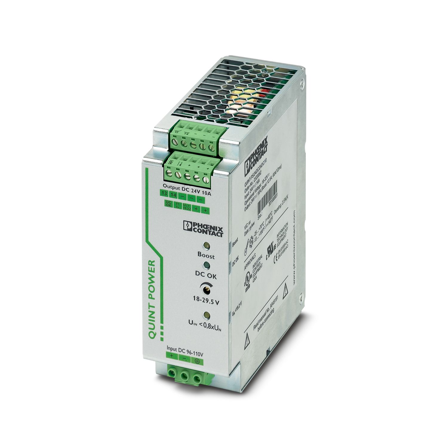
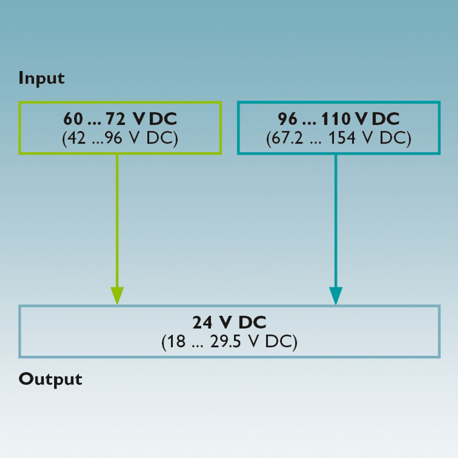
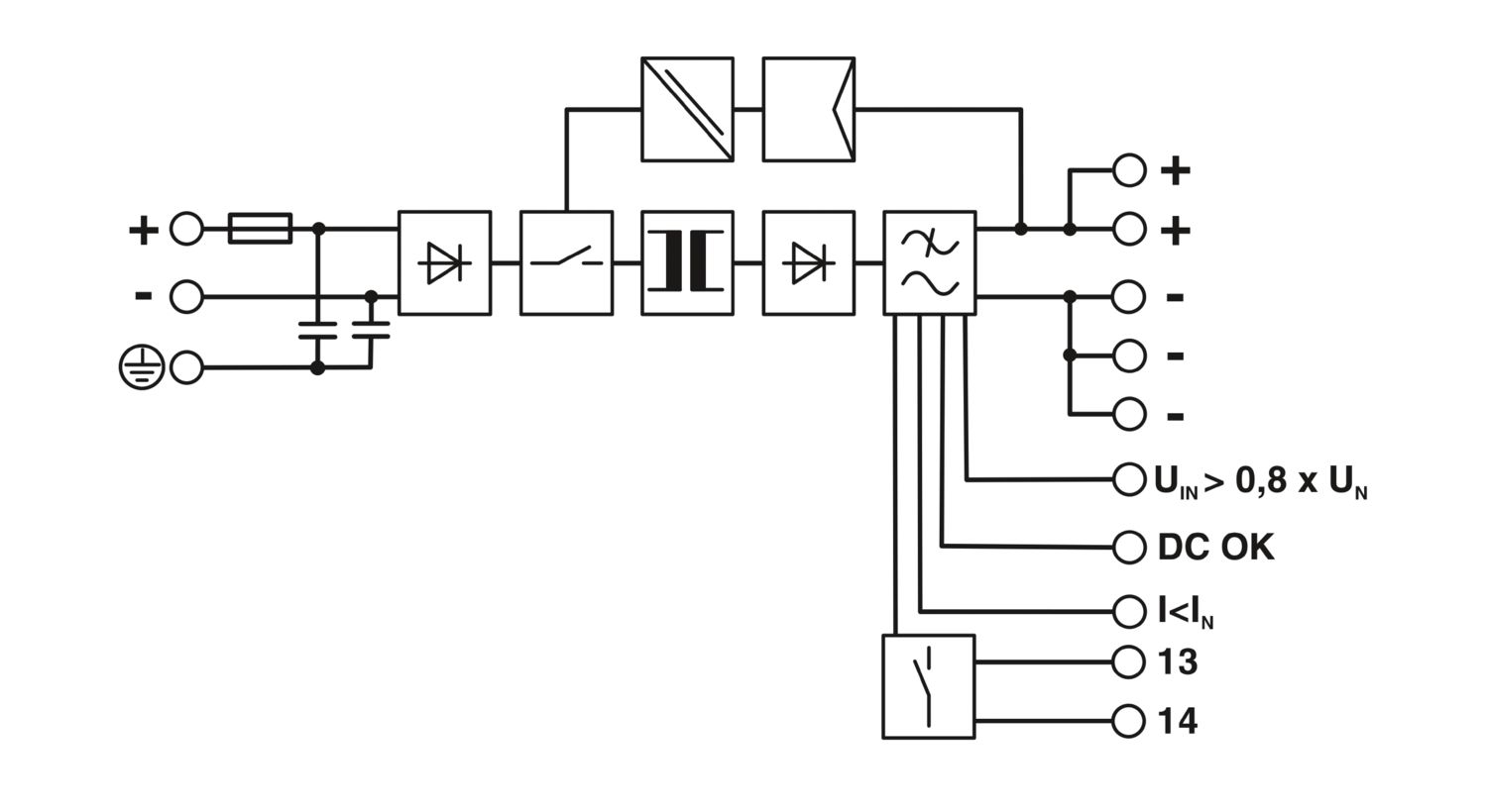
Primary-switched QUINT DC/DC converter with wide range input for DIN rail mounting with SFB (selective fuse breaking) technology, input: 96 - 110 V DC, output: 24 V DC/10 A
Detalhes dos produtos
DC operation | |
Nominal input voltage range | 96 V DC ... 110 V DC |
Input voltage range | 67.2 V DC ... 154 V DC |
Wide-range input | yes |
Input voltage range DC | 67.2 V DC ... 154 V DC |
Voltage type of supply voltage | DC |
Inrush current | < 10 A (typical) |
Inrush current integral (I2t) | 0.37 A2s |
Mains buffering time | typ. 10 ms (96 V DC) |
Current consumption | 3.5 A (96 V DC) |
3.1 A (110 V DC) | |
Reverse polarity protection | ≤ 154 V DC |
Protective circuit | Transient surge protection; Varistor |
Input fuse | 10 A 150 V DC (internal (device protection)) |
Efficiency | > 92 % (UIN 96 V DC / UOUT 24 V DC) |
> 92 % (UIN 110 V DC / UOUT 24 V DC) | |
Output characteristic | U/I |
Nominal output voltage | 24 V DC ±1 % |
Setting range of the output voltage (USet) | 18 V DC ... 29.5 V DC (> 24 V DC, constant capacity restricted) |
Nominal output current (IN) | 10 A (-40 °C ... 60 °C) |
POWER BOOST (IBoost) | 12.5 A (-40 °C ... 40 °C permanent, UOUT = 24 V DC) |
Selective Fuse Breaking (ISFB) | 60 A (12 ms) |
Magnetic circuit breaker tripping | B2 / B4 / B6 |
Derating | 60 °C ... 70 °C (2.5 %/K) |
Feedback voltage resistance | 35 V DC |
Protection against overvoltage at the output (OVP) | < 35 V DC |
Max. capacitive load | unlimited |
Active current limitation | 18 A |
Control deviation | < 1 % (change in load, static 10 % ... 90 %) |
< 2 % (change in load, dynamic 10 % ... 90 %) | |
< 0.1 % (change in input voltage ±10 %) | |
Residual ripple | < 20 mVPP |
Output power | 240 W |
Peak switching voltages nominal load | < 10 mVPP (20 MHz) |
Maximum no-load power dissipation | 4 W (UIN 110 V DC) |
Power loss nominal load max. | 22 W (UIN 110 V DC) |
Rise time | < 2 ms (UOUT (10 % ... 90 %)) |
Connection in parallel | yes, for redundancy and increased capacity |
Connection in series | yes |
Signal: DC OK active | |
Output description | UOUT > 0.9 x UN: High signal |
Switching voltage range | 18 V DC ... 24 V DC |
Maximum inrush current | < 20 mA (short-circuit-proof) |
Signal: POWER BOOST, active | |
Output description | IOUT < IN: High signal |
Switching voltage range | 18 V DC ... 24 V DC |
Maximum inrush current | < 20 mA (short-circuit-proof) |
Signal: UIN OK, active | |
Output description | UIN > 19.2 V: High signal |
Switching voltage range | 18 V DC ... 24 V DC |
Maximum inrush current | ≤ 20 mA (short-circuit-proof) |
Signal: DC OK floating | |
Output description | Relay |
Input | |
Connection method | Screw connection |
Conductor cross section, rigid min. | 0.2 mm² |
Conductor cross section, rigid max. | 2.5 mm² |
Conductor cross section flexible min. | 0.2 mm² |
Conductor cross section flexible max. | 2.5 mm² |
Conductor cross section AWG min. | 24 |
Conductor cross section AWG max. | 12 |
Stripping length | 8 mm |
Screw thread | M3 |
Tightening torque, min | 0.5 Nm |
Tightening torque max | 0.6 Nm |
Output | |
Connection method | Screw connection |
Conductor cross section, rigid min. | 0.2 mm² |
Conductor cross section, rigid max. | 2.5 mm² |
Conductor cross section flexible min. | 0.2 mm² |
Conductor cross section flexible max. | 2.5 mm² |
Conductor cross section AWG min. | 24 |
Conductor cross section AWG max. | 12 |
Stripping length | 7 mm |
Screw thread | M3 |
Tightening torque, min | 0.5 Nm |
Tightening torque max | 0.6 Nm |
Signal | |
Conductor cross section, rigid min. | 0.2 mm² |
Conductor cross section, rigid max. | 2.5 mm² |
Conductor cross section flexible min. | 0.2 mm² |
Conductor cross section flexible max. | 2.5 mm² |
Conductor cross section AWG min. | 24 |
Conductor cross section AWG max. | 12 |
Screw thread | M3 |
Tightening torque, min | 0.5 Nm |
Tightening torque max | 0.6 Nm |
Types of signaling | LED |
Active switching output | |
Relay contact | |
Signal output: DC OK active | |
Status display | "DC OK" LED green |
Color | green |
Signal output: POWER BOOST, active | |
Status display | "BOOST" LED yellow/IOUT > IN : LED on |
Color | yellow |
Note on status display | LED on |
Signal output: UIN OK, active | |
Status display | LED "UIN < 0.8 x UN V" yellow/UIN < 0.8 x UN V DC: LED on |
Color | yellow |
Note on status display | LED on |
Number of phases | 1 |
Insulation voltage input/output | 1.5 kV (type test) |
1 kV (routine test) | |
1 kV (type test) |
Product type | DC/DC converters |
Product family | QUINT POWER |
MTBF (IEC 61709, SN 29500) | > 1357000 h (25 °C) |
> 772000 h (40 °C) | |
Insulation characteristics | |
Protection class | I |
Degree of pollution | 2 |
Width | 48 mm |
Height | 130 mm |
Depth | 125 mm |
Installation dimensions | |
Installation distance right/left | 0 mm / 0 mm (≤ 70 °C) |
Installation distance right/left (active) | 15 mm / 15 mm (≤ 70 °C) |
Installation distance top/bottom | 50 mm / 50 mm (≤ 70 °C) |
Installation distance top/bottom (active) | 50 mm / 50 mm (≤ 70 °C) |
Alternative assembly | |
Width | 122 mm |
Height | 130 mm |
Depth | 51 mm |
Mounting type | DIN rail: 35 mm |
Assembly note | alignable: PN ≥50%, 5 mm horizontally, 15 mm next to active components, 50 mm vertically alignable: PN <50%, 0 mm horizontally, 40 mm vertically top, 20 mm vertically bottom |
Mounting position | horizontal DIN rail NS 35, EN 60715 |
With protective coating | no |
Housing material | Metal |
Type of housing | Aluminum (AlMg3) |
Hood version | Galvanized sheet steel, free from chrome (VI) |
Ambient conditions | |
Degree of protection | IP20 |
Ambient temperature (operation) | -25 °C ... 70 °C (> 60 °C Derating: 2,5 %/K) |
Ambient temperature (storage/transport) | -40 °C ... 85 °C |
Ambient temperature (start-up type tested) | -40 °C |
Climatic class | 3K3 (in acc. with EN 60721) |
Max. permissible relative humidity (operation) | ≤ 95 % (at 25 °C, non-condensing) |
Shock | 18 ms, 30g, in each space direction (according to IEC 60068-2-27) |
Vibration (operation) | < 15 Hz, amplitude ±2.5 mm (according to IEC 60068-2-6) |
15 Hz ... 150 Hz, 2.3g, 90 min. | |
Temp code | T4 (-25 ... +70 °C; > 60 °C, Derating: 2,5 %/K) |
Rail applications | EN 50121-4 |
Standard – Electronic equipment for use in electrical power installations and their assembly into electrical power installations | EN 50178/VDE 0160 (PELV) |
Standard - Electrical safety | EN 60950-1/VDE 0805 (SELV) |
Standard – Safety extra-low voltage | EN 60950-1 (SELV) |
EN 60204 (PELV) | |
Standard - Safe isolation | DIN VDE 0100-410 |
UL approvals | UL/C-UL listed UL 508 |
UL/C-UL Recognized UL 60950-1 | |
UL ANSI/ISA-12.12.01 Class I, Division 2, Groups A, B, C, D T4 (Hazardous Location) |
Electromagnetic compatibility | Conformance with EMC Directive 2014/30/EU |
EMC requirements for noise emission | EN 61000-6-3 |
EN 61000-6-4 | |
EMC requirements for noise immunity | EN 61000-6-1 |
EN 61000-6-2 | |
Electrostatic discharge | |
Standards/regulations | EN 61000-4-2 |
Electrostatic discharge | |
Contact discharge | 8 kV (Test Level 4) |
Discharge in air | 15 kV (Test Level 4) |
Comments | Criterion A |
Electromagnetic HF field | |
Standards/regulations | EN 61000-4-3 |
Electromagnetic HF field | |
Frequency range | 80 MHz ... 1 GHz |
Test field strength | 20 V/m (Test Level 3) |
Frequency range | 1 GHz ... 2 GHz |
Test field strength | 20 V/m (Test Level 3) |
Frequency range | 2 GHz ... 3 GHz |
Test field strength | 10 V/m (Test Level 3) |
Comments | Criterion A |
Fast transients (burst) | |
Standards/regulations | EN 61000-4-4 |
Fast transients (burst) | |
Input | 4 kV (Test Level 4 - asymmetrical) |
Output | 2 kV (Test Level 3 - asymmetrical) |
Signal | 2 kV (Test Level 4 - asymmetrical) |
Comments | Criterion A |
Surge voltage load (surge) | |
Standards/regulations | EN 61000-4-5 |
Surge voltage load (surge) | |
Input | 2 kV (Test Level 4 - symmetrical) |
4 kV (Test Level 4 - asymmetrical) | |
Output | 1 kV (Test Level 3 - symmetrical) |
2 kV (Test Level 3 - asymmetrical) | |
Signal | 1 kV (Test Level 2 - asymmetrical) |
Comments | Criterion A |
Conducted interference | |
Standards/regulations | EN 61000-4-6 |
Conducted interference | |
Input/output/signal | asymmetrical |
Frequency range | 0.15 MHz ... 80 MHz |
Comments | Criterion A |
Voltage | 10 V (Test Level 3) |
Emitted interference | |
Standards/regulations | EN 61000-6-3 |
Radio interference voltage in acc. with EN 55011 | EN 55011 (EN 55022) Class B, area of application: Industry and residential |
Emitted radio interference in acc. with EN 55011 | EN 55011 (EN 55022) Class B, area of application: Industry and residential |
Criteria | |
Criterion A | Normal operating behavior within the specified limits. |
Criterion B | Temporary impairment to operational behavior that is corrected by the device itself. |
N.º de artigo | 2905010 |
Pcs./Emb | 1 Unidade |
Quantidade mínima de pedido | 1 Unidade |
Chave comercial | CMD |
Chave de produto | CMDQ43 |
Página de catálogo | Página 295 (C-4-2019) |
GTIN | 4046356908313 |
Peso por unidade (inclusive embalagem) | 1 128,6 g |
Peso por unidade (excluindo embalagem) | 962 g |
Número do imposto alfandegário | 85044095 |
País de origem | CN |
ECLASS
ECLASS-13.0 | 27040701 |
ETIM
ETIM 9.0 | EC002540 |
UNSPSC
UNSPSC 21.0 | 39121000 |
UL Recognized
ID de certificação: E211944EAC
ID de certificação: RU S-DE.BL08.W.00764UL Listed
ID de certificação: E123528cUL Listed
ID de certificação: E123528EAC
ID de certificação: RU S-DE.BL08.W.00764CoC / Compliance Statement
ID de certificação: 18-050-00cUL Listed
ID de certificação: E199827UL Listed
ID de certificação: E199827EU RoHS | |
Cumpre os requisitos de substância segundo a Diretiva RoHS | Sim |
isenções tanto quanto conhecido | 7(a), 7(c)-I |
China RoHS | |
Environment friendly use period (EFUP) |
EFUP-25
Uma lista de declaração de acordo com a RoHS da China relativa a artigos encontra-se na área de transferências do respetivo artigo, em "Declaração do fabricante". Para todos os artigos com EFUP-E não é emitida nem necessária uma tabela de declaração de acordo com a RoHS da China.
|
EU REACH SVHC | |
Nota sobre as substâncias candidatas ao REACH (n.º CAS) | Lead (n.º CAS: 7439-92-1) |
SCIP | 7f599b4d-0152-452a-88c5-f478a7cb020a |
Produtos compatíveis
-
QUINT-ORING/24DC/2X10/1X20 - Redundancy module, with protective coating 2320173
-
UTA 107/30 - Mounting adapter 2320089
-
UWA 182/52 - Mounting adapter 2938235
-
QUINT-PS-ADAPTERS7/1 - Mounting adapter 2938196
-
CB TM1 1A SFB P - Thermal-magnetic device circuit breaker 2800836
-
CB TM1 2A SFB P - Thermal-magnetic device circuit breaker 2800837
-
CB TM1 3A SFB P - Thermal-magnetic device circuit breaker 2800838
-
CB TM1 4A SFB P - Thermal-magnetic device circuit breaker 2800839
-
CB TM1 5A SFB P - Thermal-magnetic device circuit breaker 2800840
-
CB TM1 12A SFB P - Thermal-magnetic device circuit breaker 2800844
-
CB TM1 16A SFB P - Thermal-magnetic device circuit breaker 2800845
Vantagens
Reliable starting of difficult loads, thanks to the static POWER BOOST power reserve with up to 125% nominal current permanently
Preventive function monitoring indicates critical operating states before errors occur
Constant voltage: output voltage regenerated even at the end of long cables
Support conversion to various voltage levels
Electrical isolation: for setting up independent supply systems
Phoenix Contact S.A.
Sintra Business Park, Edifício n°1 Zona Industrial da Abrunheira, sala 0M, 2710-089 SINTRA