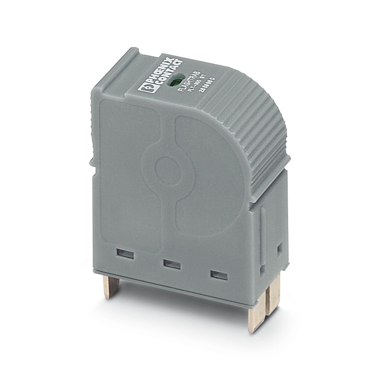
FLT-CP-3S-350
-
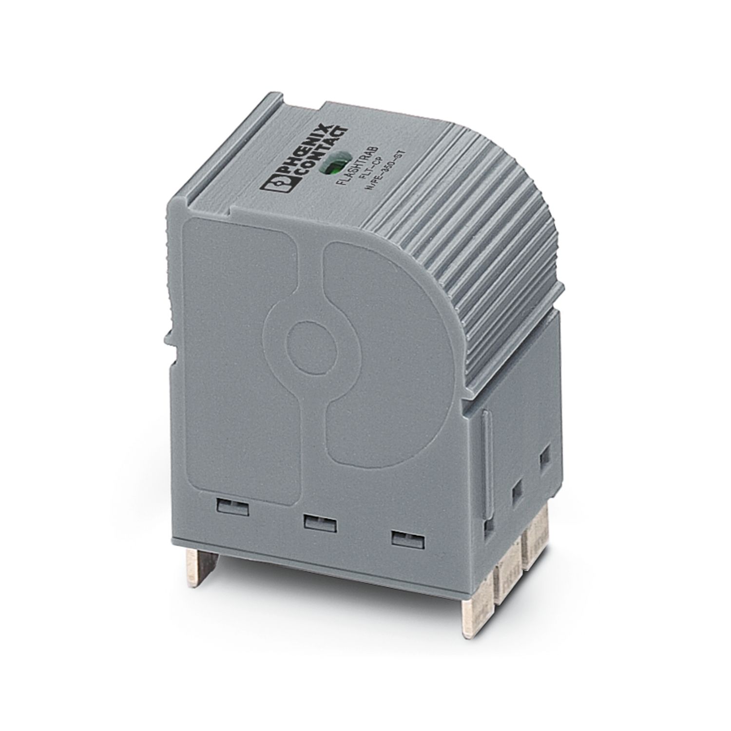
Type 1+2 special combined lightning current and surge arrester
2859712
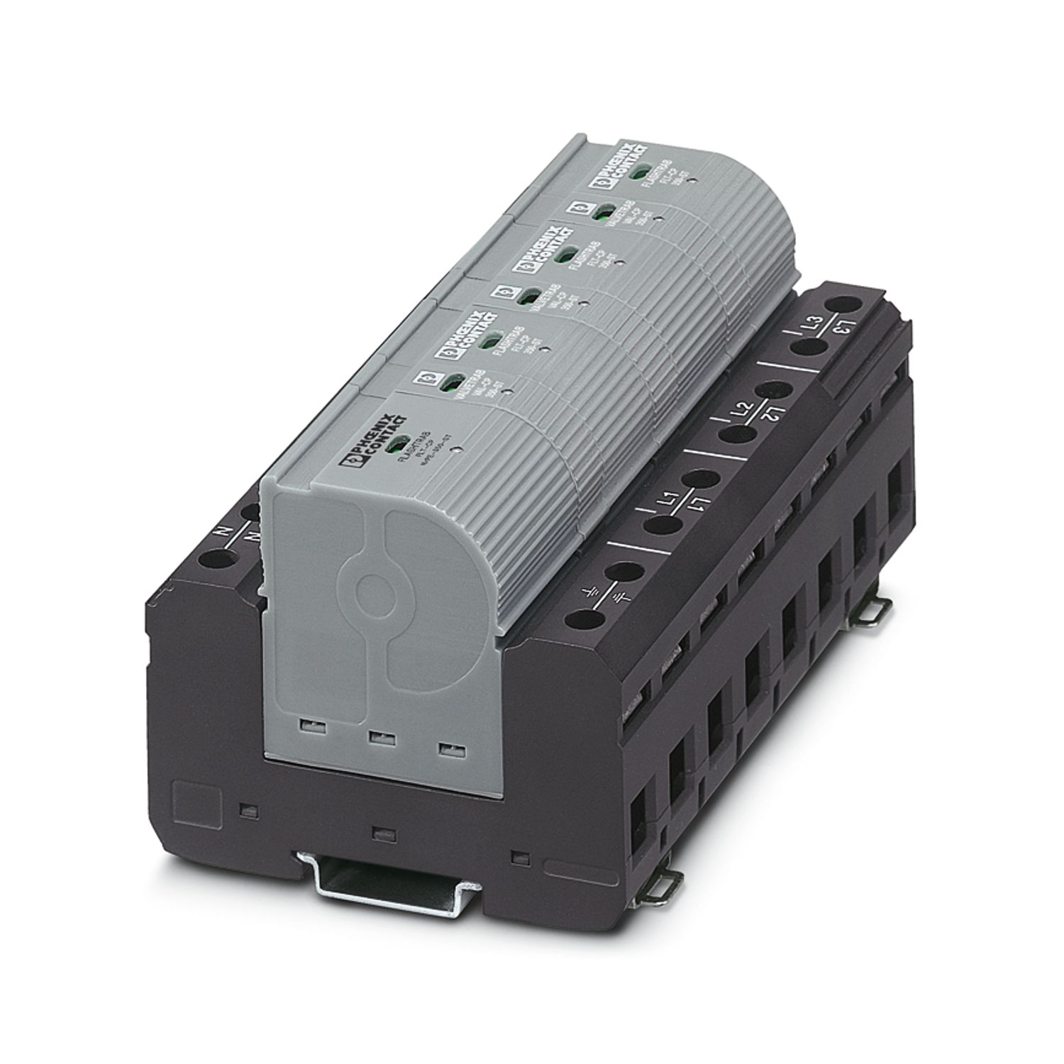
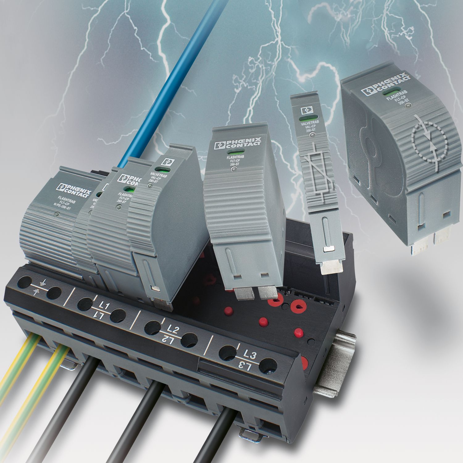

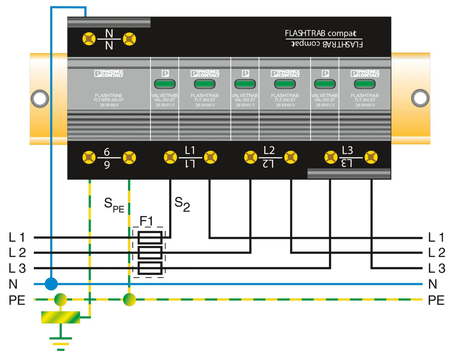
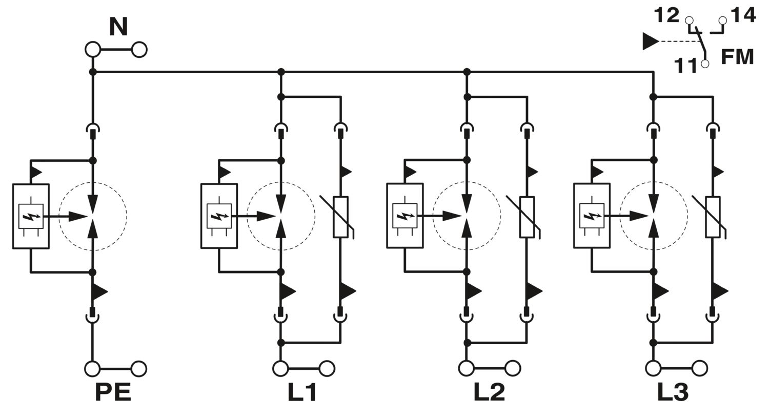
Pluggable lightning current and surge arrester combination, in acc. with typ 1+2 / Class I+II / B+C arresters. Arresters coordinated following the AEC principle, for 3-phase power supply networks with separately installed PE and N (L1, L2, L3, PE, N).
Product details
| IEC test classification | I + II |
| T1 + T2 | |
| EN type | T1 + T2 |
| IEC power supply system | TN-S |
| TT | |
| Type | DIN rail module, two-section, divisible |
| Number of positions | 4 |
| Surge protection fault message | Optical, remote indicator contact |
| Arrester can be tested with CHECKMASTER from software version: | From SW rev. 3.00 |
| Insulation characteristics | |
| Overvoltage category | III |
| Pollution degree | 2 |
| Nominal frequency fN | 50 Hz (60 Hz) |
| Indicator/remote signaling | |
| Connection name | Remote fault indicator contact |
| Switching function | Changeover contact |
| Operating voltage | 12 V AC ... 250 V AC |
| 125 V DC (200 mA DC) | |
| Operating current | 10 mA AC ... 1 A AC |
| 1 A DC (30 V DC) | |
| Connection method | Screw terminal blocks |
| Screw thread | M5 |
| Tightening torque | 4.5 Nm |
| Stripping length | 18 mm |
| Conductor cross-section flexible | 2.5 mm² ... 25 mm² |
| Conductor cross-section rigid | 2.5 mm² ... 35 mm² |
| Conductor cross-section AWG | 13 ... 2 |
| Remote fault indicator contact | |
| Connection method | Plug-in/screw connection via COMBICON |
| Screw thread | M2 |
| Tightening torque | 0.25 Nm |
| Stripping length | 7 mm |
| Conductor cross-section flexible | 0.14 mm² ... 1.5 mm² |
| Conductor cross-section rigid | 0.14 mm² ... 1.5 mm² |
| Conductor cross-section AWG | 28 ... 16 |
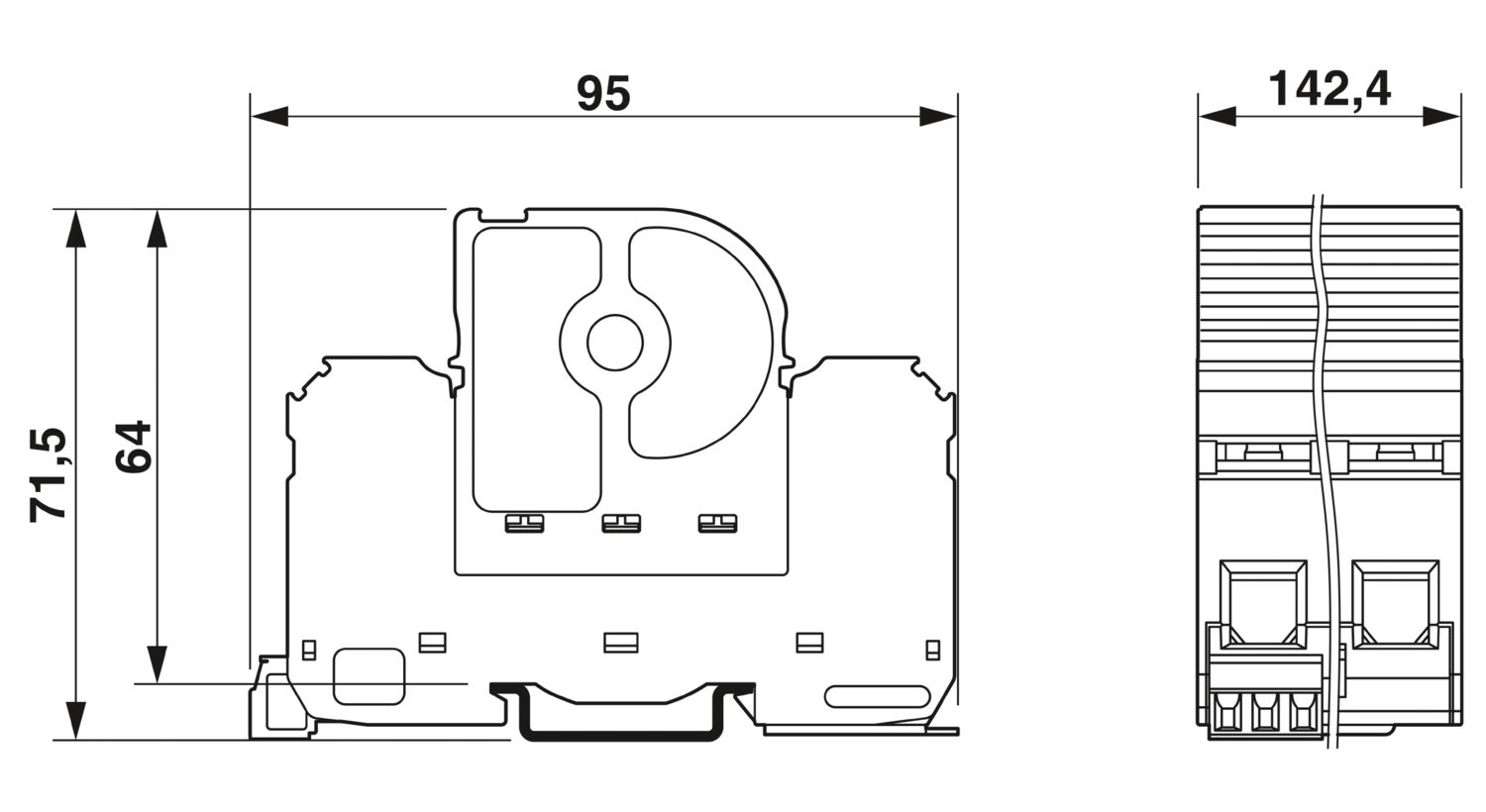
| Dimensional drawing |
|
| Width | 142.4 mm |
| Height | 95 mm |
| Depth | 71.5 mm |
| Horizontal pitch | 8 Div. |
| Flammability rating according to UL 94 | V-0 |
| CTI value of material | 600 |
| Insulating material | PA 6.6/PBT |
| Material group | I |
| Housing material | PBT |
| Mechanical data | |
| Open side panel | No |
| Mode of protection | L-N |
| L-PE | |
| N-PE | |
| Direction of action | 3L-N & N-PE |
| Nominal voltage UN | 240/415 V AC (TN-S) |
| 240/415 V AC (TT) | |
| Nominal frequency fN | 50 Hz (60 Hz) |
| Maximum continuous operating voltage UC (L-N) | 350 V AC |
| Maximum continuous operating voltage UC (N-PE) | 350 V AC |
| Rated load current IL | 125 A (< 55 °C) |
| Protective conductor current IPE | ≤ 0.01 mA |
| Standby power consumption PC | ≤ 300 mVA |
| Nominal discharge current In (8/20) µs (L-N) | 25 kA |
| Nominal discharge current In (8/20) µs (L-PE) | 25 kA |
| Nominal discharge current In (8/20) µs (N-PE) | 100 kA |
| Impulse discharge current (10/350) µs (L-N), charge | 12.5 As |
| Impulse discharge current (10/350) µs (L-N), specific energy | 160 kJ/Ω |
| Impulse discharge current (10/350) µs (L-N), peak current value Iimp | 25 kA |
| Impulse discharge current (10/350) µs (L-PE), charge | 12.5 As |
| Impulse discharge current (10/350) µs (L-PE), specific energy | 160 kJ/Ω |
| Impulse discharge current (10/350) µs (L-PE), peak current value Iimp | 25 kA |
| Impulse discharge current (10/350) µs (N-PE), charge | 50 As |
| Impulse discharge current (10/350) µs (N-PE), specific energy | 2500 kJ/Ω |
| Impulse discharge current (10/350) µs (N-PE), peak current value Iimp | 100 kA |
| Follow current quenching capacity Ifi (L-N) | 25 kA (264 V AC) |
| 3 kA (350 V AC) | |
| Follow current interrupt rating Ifi (N-PE) | 100 A (350 V AC) |
| Short-circuit current rating ISCCR | 25 kA (264 V AC) |
| 3 kA (350 V AC) | |
| Voltage protection level Up (L-N) | ≤ 1.5 kV |
| Voltage protection level Up (L-PE) | ≤ 2.2 kV |
| Voltage protection level Up (N-PE) | ≤ 1.5 kV |
| Residual voltage Ures (L-N) | ≤ 1.5 kV (at In) |
| ≤ 1.2 kV (at 10 kA) | |
| ≤ 1 kV (at 5 kA) | |
| ≤ 0.9 kV (at 3 kA) | |
| Residual voltage Ures (L-PE) | ≤ 2.2 kV (at In) |
| ≤ 2 kV (at 10 kA) | |
| ≤ 1.8 kV (at 5 kA) | |
| ≤ 1.6 kV (at 3 kA) | |
| Residual voltage Ures (N-PE) | ≤ 1.5 kV (at In) |
| ≤ 1 kV (at 10 kA) | |
| ≤ 0.9 kV (at 5 kA) | |
| ≤ 0.8 kV (at 3 kA) | |
| TOV behavior at UT (L-N) | 415 V AC (5 s / withstand mode) |
| 457 V AC (120 min / safe failure mode) | |
| TOV behavior at UT (N-PE) | 1200 V AC (200 ms / withstand mode) |
| Response time tA (L-N) | ≤ 25 ns |
| Response time tA (N-PE) | ≤ 100 ns |
| Max. backup fuse with V-type through wiring | 125 A (gG) |
| Max. backup fuse with branch wiring | 315 A (gG) |
| Ambient conditions | |
| Degree of protection | IP20 (only when all terminal points are used) |
| Ambient temperature (operation) | -40 °C ... 80 °C |
| Ambient temperature (storage/transport) | -40 °C ... 80 °C |
| Altitude | ≤ 2000 m (amsl) |
| Permissible humidity (operation) | 5 % ... 95 % |
| Shock (operation) | 25g (Half-sine / 11 ms / 3x ±X, ±Y, ±Z) |
| Vibration (operation) | 5g (5 - 500 Hz/2.5 h/X, Y, Z) |
| UL specifications | |
| Maximum continuous operating voltage MCOV (L-L) | 528 V AC |
| Maximum continuous operating voltage MCOV (L-N) | 264 V AC |
| Maximum continuous operating voltage MCOV (L-G) | 528 V AC |
| Maximum continuous operating voltage MCOV (N-G) | 264 V AC |
| Nominal discharge current In (L-L) | 20 kA |
| Nominal discharge current In (L-N) | 20 kA |
| Nominal discharge current In (L-G) | 20 kA |
| Nominal discharge current In (N-G) | 20 kA |
| Mode of protection | L-L |
| L-N | |
| L-G | |
| N-G | |
| Nominal voltage | 240/415 V AC |
| Power distribution system | Wye |
| Nominal frequency | 50/60 Hz |
| Measured limiting voltage MLV (L-L) | 2470 V |
| Measured limiting voltage MLV (L-N) | 1340 V |
| Measured limiting voltage MLV (L-G) | 1550 V |
| Measured limiting voltage MLV (N-G) | 1080 V |
| Follow current (L-N) | 10 kA (264 V AC) |
| Follow current (L-G) | 200 A (264 V AC) |
| SPD Type | 4CA |
| UL indicator/remote signaling | |
| Operating voltage | 125 V AC |
| AC operating current | 1 A AC |
| UL connection data | |
| Tightening torque | 40 lbf-in. |
| Conductor cross-section AWG | 12 ... 2 |
| Air clearances and creepage distances | |
| Standards/regulations | DIN VDE 0110-1 / IEC 60664-1 / IEC 61643-1 |
| Standards/specifications | IEC 61643-11 |
| Note | 2011 |
| Standards/specifications | EN 61643-11 |
| Note | 2012 |
| Mounting type | DIN rail: 35 mm |