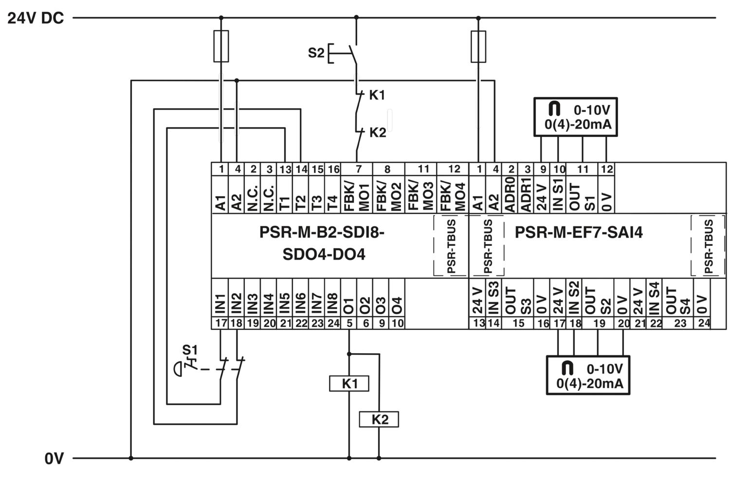
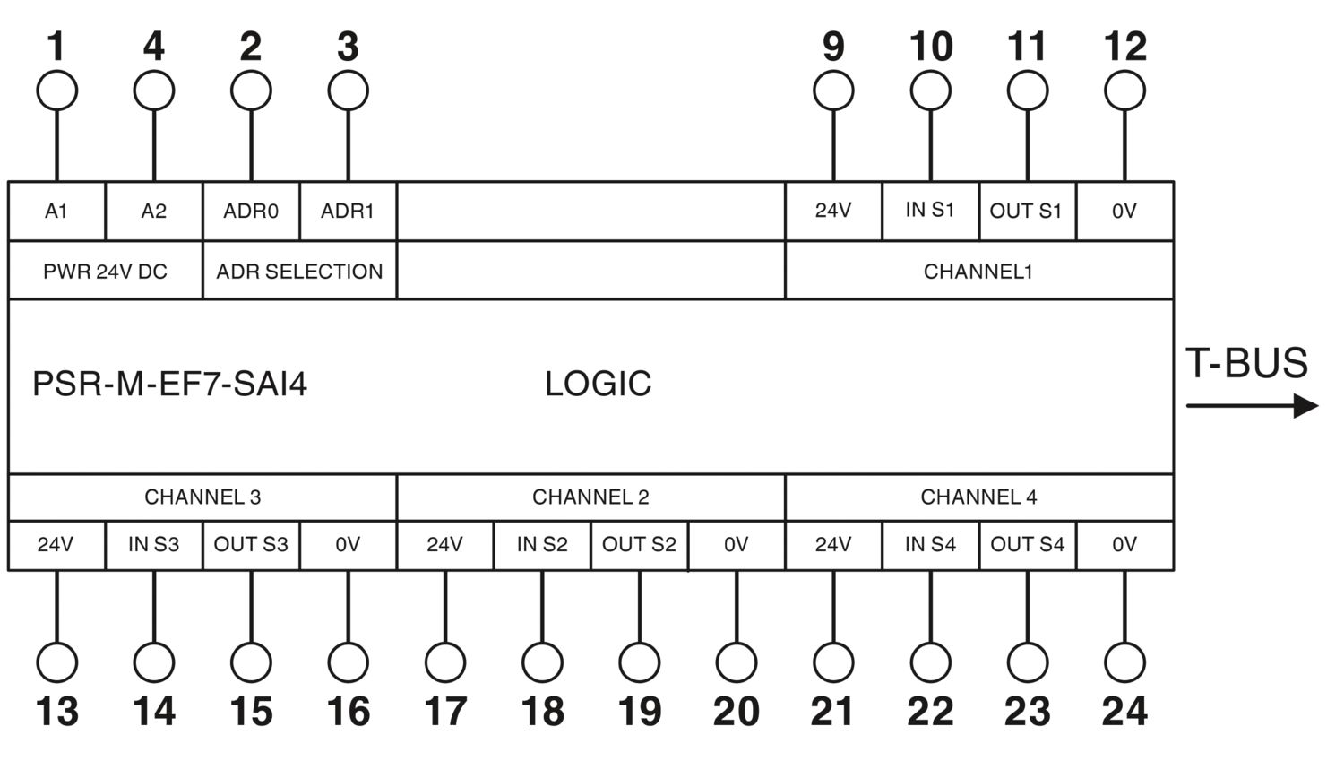
The configurable and individually scalable PSRmodular safety system is a flexible safety solution for monitoring your machine or system. The safe extension module provides the system with additional safe analog inputs.
PSR-M-EF7-SAI4-SC
-
Extension module
1104985
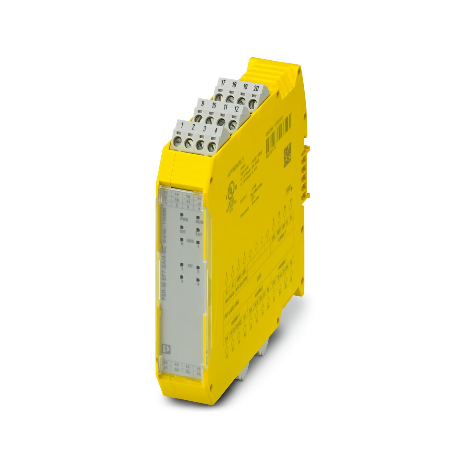
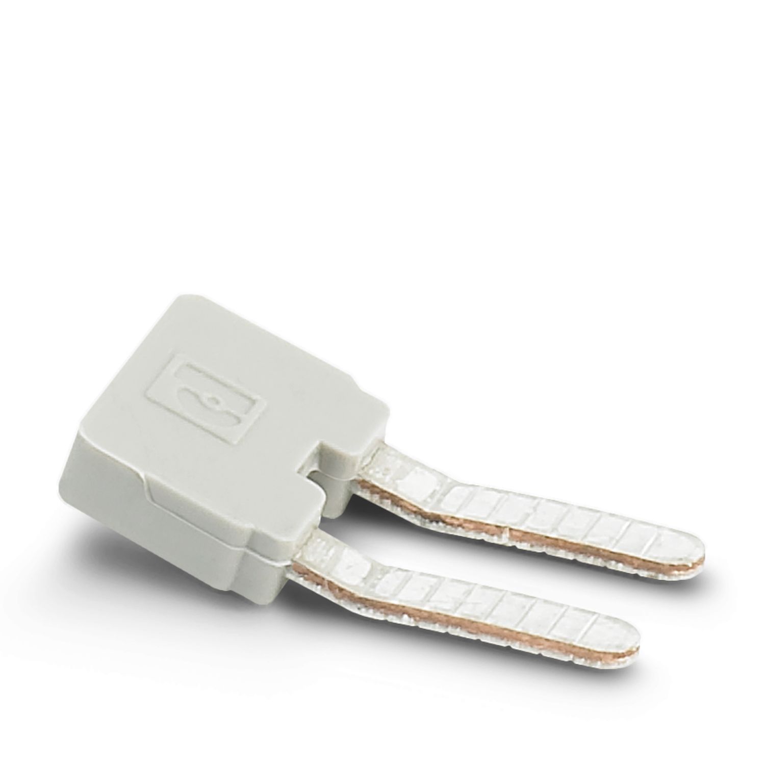
Safe extension module with 4 safe analog inputs, 0 V ... 10 V; 0 mA or 4 mA ... 20 mA; TBUS interface, up to Cat. 4/PL e, SIL 3, plug-in screw terminal block, TBUS connector included
Free download available.
Downloads
Product details
| Note on application | Only for industrial use |
| Note on application | As things stand now, we are preparing the product so that, as of December 11, 2027, it will comply with the requirements of the EU Cyber Resilience Act (CRA) based on the information currently available regarding the CRA. |
| Product type | Safety device |
| Application | Analog IN |
| Control | 1 and 2 channel |
| Special properties | The product is being prepared for compliance with the Cyber Resilience Act (CRA) |
| Insulation characteristics | |
| Protection class | III |
| Insulation characteristics | |
| Overvoltage category | II |
| Degree of pollution | 2 |
| Times | |
| Response time | see user manual |
| Restart time | min. 5 s (Boot time) |
| max. 10 s (Boot time) | |
| Maximum power dissipation for nominal condition | 2.76 W (with max. permissible load) |
| Nominal operating mode | 100% operating factor |
| Interfaces | DIN rail TBUS for connection to the master module, supplied as standard |
| Rated surge voltage/insulation | Basic insulation 4 kV between all current paths and housing |
| Electrical isolation, 0.5 kV functional insulation between logic and analog inputs and between the analog inputs | |
| Supply | |
| Designation | A1/A2 |
| Rated control circuit supply voltage US | 19.2 V DC ... 28.8 V DC |
| Rated control circuit supply voltage US | 24 V DC -20 % / +20 % (external fuse, typically 6 A) |
| Rated control supply current IS | typ. 82 mA (without sensor supply) |
| typ. 212 mA (with sensor supply) | |
| Power consumption at US | typ. 1.96 W (without sensor supply) |
| typ. 5.08 W (with sensor supply) | |
| Inrush current | max. 14 A (Δt = 1 ms at Us) |
| Filter time | typ. 5 ms (in the event of voltage dips at Us) |
| Protective circuit | Serial protection against polarity reversal |
| Analog | |
| Input name | IN S1, IN S2, IN S3, IN S4 |
| Description of the input | Safety-oriented analog inputs, configurable as current or voltage inputs, galvanically isolated |
| Number of inputs | 4 |
| Connection technology | 2-conductor, 3-conductor or 4-conductor (2-conductor sensor signal + 2-conductor sensor supply) |
| Note regarding the connection technology | shielded |
| Scanning rate | 2.5/5/10/16.6/20/50/60/100/200/400/800/1000/2000/4000 Hz |
| Current input signal | 0 mA ... 25 mA (Measuring range) |
| 0 mA ... 20 mA (Configurable measuring range with diagnostics range 20.1 mA ... 23 mA) | |
| 4 mA ... 20 mA (Configurable measuring range with diagnostics range 20.1 mA ... 23 mA (upper limit), 2.5 mA ... 3.8 mA (lower limit)) | |
| Voltage input signal | 0 V ... 12 V (Measuring range) |
| 0 V ... 10 V (Configurable measuring range with diagnostics range 10.05 V ... 11.5 V (upper limit), 0.1 V (lower limit)) | |
| Max. permissible current | max. 35 mA (as current input) |
| Permissible voltage | max. 24 V (as current input) |
| max. 14 V (as voltage input) | |
| Input resistance current input | 290 Ω ±25 % (incl. internal protective circuit) |
| Input resistance of voltage input | 185 kΩ ±25 % |
| A/D converter resolution | 16 bit |
| Resolution (current) | 381 nA |
| Resolution (voltage) | 152 µV |
| Precision | typ. ± 2 % (as current input, relative to the upper range value) |
| max. ± 2.5 % (as current input) | |
| typ. ± 1 % (as voltage input, relative to the upper range value) | |
| max. ± 1.5 % (as voltage input) | |
| Temperature coefficients | typ. ± 0.07 %/K |
| max. ± 0.07 %/K | |
| Limit frequency (3 dB) | 160 Hz (RC low pass, 1st order, as current input) |
| 4 Hz (RC low pass, as voltage input) | |
| Frequency | see user manual |
| Permissible cable length | max. 100 m (per input) |
| Protective circuit | Overload protection of the current inputs |
| Overload protection of the voltage inputs | |
| Sensor supply: OUT S1/0V ...OUT S4/0V | |
| Description | Sensor supply voltage per analog input |
| Supply voltage | 24 V DC ±3 % |
| Current | max. 30 mA (Sensor current recording per channel) |
| Short-circuit-proof | yes |
| Protective circuit | Overload protection Overload detection at 38 mA |
| Connection technology | |
| pluggable | yes |
| Conductor connection | |
| Connection method | Screw connection |
| Conductor cross-section rigid | 0.2 mm² ... 2.5 mm² |
| Conductor cross-section flexible | 0.2 mm² ... 2.5 mm² |
| Conductor cross-section AWG | 24 ... 12 |
| Stripping length | 7 mm |
| Screw thread | M3 |
| Tightening torque | 0.5 Nm ... 0.6 Nm |
| Status display | 4 x LED (yellow, red) |
| Operating voltage display | 1 x LED (green) |
| Width | 22.61 mm |
| Height | 112.58 mm |
| Depth | 113.6 mm |
| Color (Housing) | yellow (RAL 1018) |
| Housing material | Polyamide PA non-reinforced |
| Safety data | |
| Stop category (EN 60204-1) | 0 |
| Safety data: EN ISO 13849 | |
| Performance level (PL) | e (2-channel wiring) |
| d (1-channel wiring) | |
| Safety data: IEC 61508 - High-demand for 2-channel wiring | |
| Safety Integrity Level (SIL) | 3 |
| Safety data: IEC 61508 - High-demand for 1-channel wiring | |
| Safety Integrity Level (SIL) | 2 |
| Safety data: EN IEC 62061 | |
| Safety Integrity Level (SIL) | 3 (2-channel wiring) |
| 2 (1-channel wiring) | |
| Ambient conditions | |
| Degree of protection | IP20 |
| Min. degree of protection of inst. location | IP54 |
| Ambient temperature (operation) | -10 °C ... 55 °C (observe derating) |
| Ambient temperature (storage/transport) | -20 °C ... 85 °C |
| Maximum altitude | ≤ 2000 m (Above sea level) |
| Max. permissible humidity (storage/transport) | 95 % (non-condensing) |
| Max. permissible relative humidity (operation) | 95 % (non-condensing) |
| Shock | 10g for Δt = 16 ms (continuous shock, 1000 shocks in each space direction) |
| Vibration (operation) | 10 Hz ... 150 Hz, 2g |
| CE | |
| Identification | CE-compliant |
| Mounting type | DIN rail mounting |
| Assembly note | Observe derating |
| Mounting position | vertical or horizontal |
| Item number | 1104985 |
| Packing unit | 1 pc |
| Minimum order quantity | 1 pc |
| Product key | DNA362 |
| GTIN | 4055626971063 |
| Weight per piece (including packing) | 208 g |
| Weight per piece (excluding packing) | 160 g |
| Customs tariff number | 85371098 |
| Country of origin | IT |
ECLASS
| ECLASS-13.0 | 27371819 |
| ECLASS-15.0 | 27371819 |
| ECLASS-15.0 ASSET | 27250101 |
ETIM
| ETIM 10.0 | EC001449 |
UNSPSC
| UNSPSC 21.0 | 39122200 |
| EU RoHS | |
| Fulfills EU RoHS substance requirements | Yes (No exemptions) |
| China RoHS | |
| Environment friendly use period (EFUP) |
EFUP-E
No hazardous substances above the limits
|
| EU REACH SVHC | |
| REACH candidate substance (CAS No.) | No substance above 0.1 wt% |
Compatible products
Your advantages
Cost-effective safety solution with a high level of adaptability to individual requirements
Fast startup, thanks to easy hardware and software configuration
Machine downtimes minimized with comprehensive, easy-to-understand diagnostics
Low housing width of just 22.6 mm
Up to Cat. 4/PL e in accordance with ISO 13849-1, SIL 3 in accordance with EN IEC 62061, SIL 3 in accordance with IEC 61508
Suitable for elevator applications in accordance with EN 81-20
Phoenix Contact GmbH & Co. KG
Flachsmarktstraße 8, D-32825 Blomberg