
PTCB E1 24DC/1-3A NO
-
Electronic circuit breaker
2909909
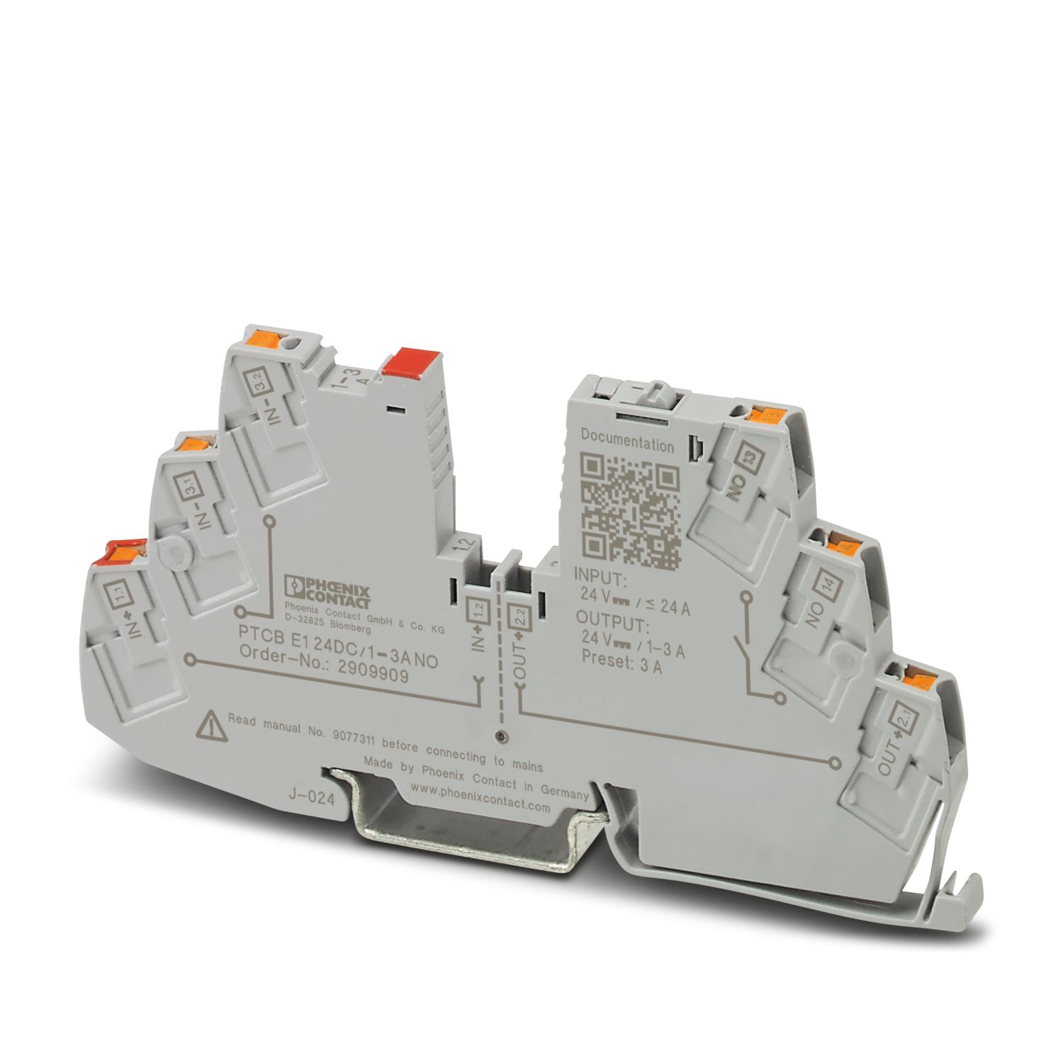
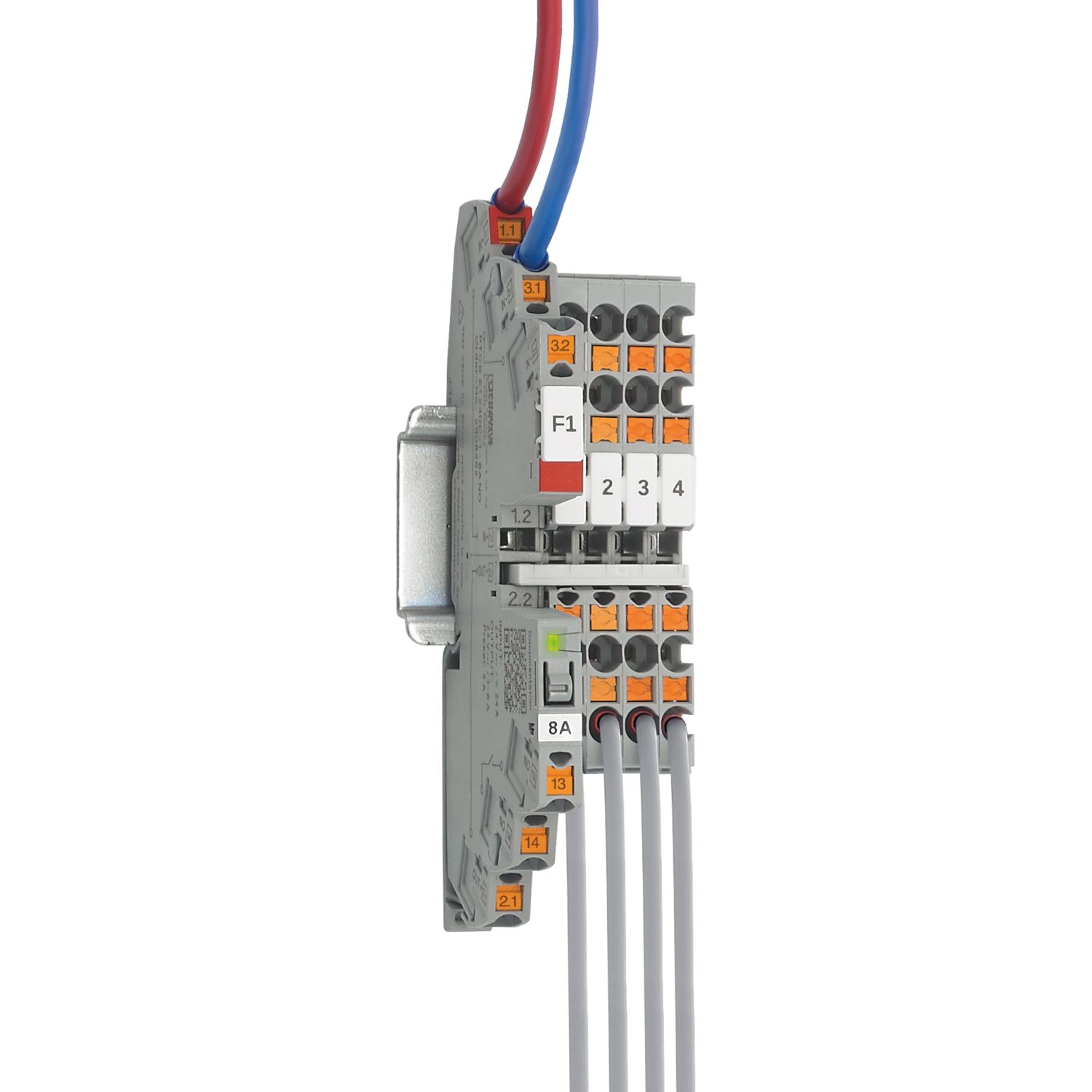
1-channel, electronic circuit breaker for protecting loads at 24 V DC against overload and short circuit. Easy potential distribution with components from the CLIPLINE complete terminal block system. With electronic interlock of the set nominal currents. For installation on DIN rails.
Product details
| General | |
| Note | EN 50121-3-2: Railway applications - Electromagnetic compatibility - Part 3-2: Rolling stock – Apparatus |
| Connection for signal line tested in accordance with EN 61000-4-4 with 1 kV; if necessary, customer must provide appropriate protective measures | |
| Repeated hard short circuits can reduce the melting integral of the integrated backup fuse. | |
| Always connect the negative pole to terminal IN- to ensure the internal power supply. Return currents from the loads must not be fed back to the power supply via IN- of the circuit breaker. | |
| Product type | Device circuit breakers |
| Product family | PTCB |
| Type | DIN rail module, one-piece |
| Number of positions | 1 |
| No. of channels | 1 |
| Insulation characteristics | |
| Protection class | III |
| Pollution degree | 2 |
| General | |
| Operating voltage | 18 V DC ... 27.5 V DC |
| Rated voltage | 24 V DC |
| Rated current IN | 24 A (Total current input) |
| 3 A (Rated current output) | |
| Rated current IN | 1 / 2 / 3 A DC (adjustable) |
| Rated current (pre-adjusted) | 3 A |
| Rated surge voltage | 0.5 kV |
| Tripping method | E (electronic) |
| Feedback resistance | max. 35 V DC |
| Required backup fuse | Only required if Imax of the power supply > the short-circuit switching capacity. Integrated failsafe element. |
| Short-circuit switching capacity | 300 A |
| Dielectric strength | max. 35 V DC (Load circuit) |
| Fuse | electronic |
| Efficiency | > 99 % |
| Closed circuit current I0 | typ. 12 mA |
| Power dissipation | typ. 0.3 W (No-load operation) |
| < 0.9 W (Nominal operation) | |
| Module initialization time | < 0.55 s |
| Waiting time after switch off of a channel | 5 s (at overload / short circuit) |
| Measuring tolerance I | ± 15 % |
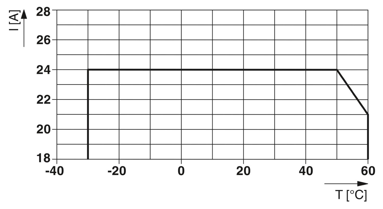
| Temperature derating | 21 A (Total current at 60°C) |
| 24 A (Total current at 50°C) | |
| 3 A (Channel current at 60°C) | |
| 3 A (Channel current at 50°C) | |
| MTBF (IEC 61709, SN 29500) | 28571428 h (at 25 °C with 21 % load) |
| 14084507 h (at 40°C with 34.25% load) | |
| 2053388 h (at 60°C with 100% load) | |
| Voltage drop | 0.06 V (at 2 A) |
| Fail-safe element | 4 A DC |
| Contact switching type | without electrical isolation |
| Load circuit | |
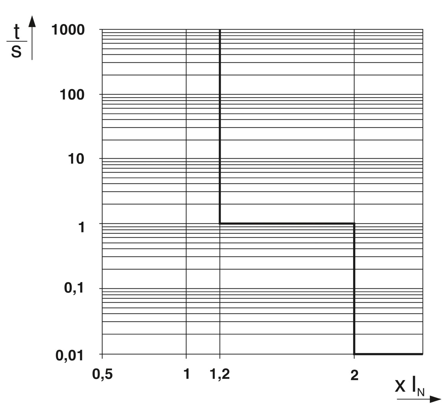
| Shutdown time | ≤ 10 ms (for short circuit > 2.0 x IN) |
| 1 s (1.2 ... 2.0 x IN) | |
| Undervoltage switch-off | ≤ 17.8 V DC (active) |
| ≥ 18.8 V DC (inactive) | |
| Overvoltage switch-off | ≥ 27.5 V DC (active) |
| ≤ 27 V DC (inactive) | |
| Max. capacitive load | 14000 µF (Depending on the current setting and the short-circuit current available) |
| Indicator/remote signaling | |
| Connection name | Remote indication circuit |
| Switching function | N/O contact |
| Operating voltage | 0 V DC ... 30 V DC |
| Operating current | 100 mA DC |
| Main circuit IN+ | |
| Connection method | Push-in connection |
| Stripping length | 8 mm |
| Conductor cross-section flexible | 0.2 mm² ... 2.5 mm² |
| Conductor cross-section rigid | 0.2 mm² ... 4 mm² |
| Conductor cross-section AWG | 24 ... 12 |
| Conductor cross-section, flexible, with ferrule, with plastic sleeve | 0.2 mm² ... 2.5 mm² |
| Conductor cross-section, flexible, with ferrule, without plastic sleeve | 0.2 mm² ... 2.5 mm² |
| Main circuit IN- | |
| Connection method | Push-in connection |
| Stripping length | 8 mm |
| Conductor cross-section flexible | 0.2 mm² ... 2.5 mm² |
| Conductor cross-section rigid | 0.2 mm² ... 4 mm² |
| Conductor cross-section AWG | 24 ... 12 |
| Conductor cross-section, flexible, with ferrule, with plastic sleeve | 0.2 mm² ... 2.5 mm² |
| Conductor cross-section, flexible, with ferrule, without plastic sleeve | 0.2 mm² ... 2.5 mm² |
| Main circuit OUT | |
| Connection method | Push-in connection |
| Stripping length | 8 mm |
| Conductor cross-section flexible | 0.2 mm² ... 2.5 mm² |
| Conductor cross-section rigid | 0.2 mm² ... 4 mm² |
| Conductor cross-section AWG | 24 ... 12 |
| Conductor cross-section, flexible, with ferrule, with plastic sleeve | 0.2 mm² ... 2.5 mm² |
| Conductor cross-section, flexible, with ferrule, without plastic sleeve | 0.2 mm² ... 2.5 mm² |
| Remote indication circuit | |
| Connection method | Push-in connection |
| Stripping length | 8 mm |
| Conductor cross-section flexible | 0.2 mm² ... 2.5 mm² |
| Conductor cross-section rigid | 0.2 mm² ... 4 mm² |
| Conductor cross-section AWG | 24 ... 14 |
| Conductor cross-section, flexible, with ferrule, with plastic sleeve | 0.2 mm² ... 2.5 mm² |
| Conductor cross-section, flexible, with ferrule, without plastic sleeve | 0.2 mm² ... 2.5 mm² |
| Channel LED off | off (Channel switched off) |
| Channel LED yellow | lit (Channel switched on, channel load > 80% ) |
| flashing (Programming mode active) | |
| Channel LED green | lit (Channel switched on) |
| Channel LED red | lit (Channel switched off, over- or undervoltage active) |
| ON temporarily (Channel switched off, 5 s cool-down phase, overload or short-circuit release) | |
| flashing (Channel switched off, ready to be switched back on, overload or short-circuit release) | |
| flashing quickly (Channel switched off, external voltage at the output, possible installation error) |
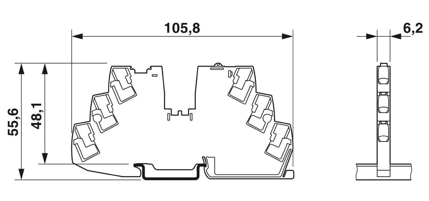
| Dimensional drawing |
|
| Width | 6.2 mm |
| Height | 105.8 mm |
| Depth | 55.6 mm (incl. DIN rail 7.5 mm) |
| Color | gray (RAL 7042) |
| Material | PBT |
| PBT | |
| Flammability rating according to UL 94 | V-0 |
| Ambient conditions | |
| Degree of protection | IP20 |
| Ambient temperature (operation) | -30 °C ... 60 °C |
| Ambient temperature (storage/transport) | -40 °C ... 70 °C |
| Altitude | ≤ 3000 m up to 52 °C (amsl) |
| ≤ 4000 m up to 46 °C (amsl) | |
| Humidity test | 96 h, 95 % RH, 40 °C |
| Shock (operation) | 30g (IEC 60068-2-27, Test Ea) |
| Vibration (operation) | 10 Hz ... 59.6 Hz (Amplitude ±0.35 mm; in accordance with IEC 60068-2-6, Test Fc) |
| 59.6 Hz ... 150 Hz (Acceleration 5g; in accordance with IEC 60068-2-6, Test Fc) | |
| 5 Hz ... 100 Hz (Resonance search 4g; resonance frequency 4g; 90 min in accordance with DNV GL Class B) | |
| UL approval | |
| Identification | UL/C-UL Listed UL 508 |
| UL Recognized UL 2367 | |
| NEC Class 2 according to UL 1310 | |
| UL/C-UL Listed ANSI/UL 121201 Class I, Division 2, Groups A, B, C, D; T4 (Hazardous Location) | |
| Shipbuilding approval | |
| Identification | DNV GL |
| Corrosive gas test | |
| Identification | ISA S71.04.2013 G3 Harsh Group A |
| Shipbuilding data | |
| Temperature | D |
| Humidity | B |
| Vibration | B |
| EMC | B |
| Enclosure | A |
| Standards/specifications | EN 61000-6-2 |
| Note | EMC – Immunity for industrial areas |
| Standards/specifications | EN 61000-6-3 |
| Note | EMC – Emission for residential, business and commercial properties and small operations |
| Standards/specifications | EN 60068-2-78 |
| Note | Environmental influences – Moisture and heat, constant |
| Standards/specifications | EN 50178 |
| Note | Equipping power installations with electronic equipment |
| Standards/specifications | EN 60068-2-6 |
| Note | Environmental influences – Vibrations (sinusoidal) |
| Standards/specifications | EN 60068-2-27 |
| Note | Environmental influences – Shocks |
| Standards/specifications | EN 60068-2-30 |
| Note | Environmental influences – Part 2–30: Tests – Test Db: Damp heat, cyclical |
| Standards/specifications | EN 61373 |
| Note | Railway applications - Rolling stock equipment - Shock and vibration tests |
| Standards/specifications | EN 45545-2 |
| Note | Railway applications - Fire protection on railway vehicles - Part 2: Requirements for fire behavior of materials and components |
| Mounting type | DIN rail: 35 mm |


Your advantages
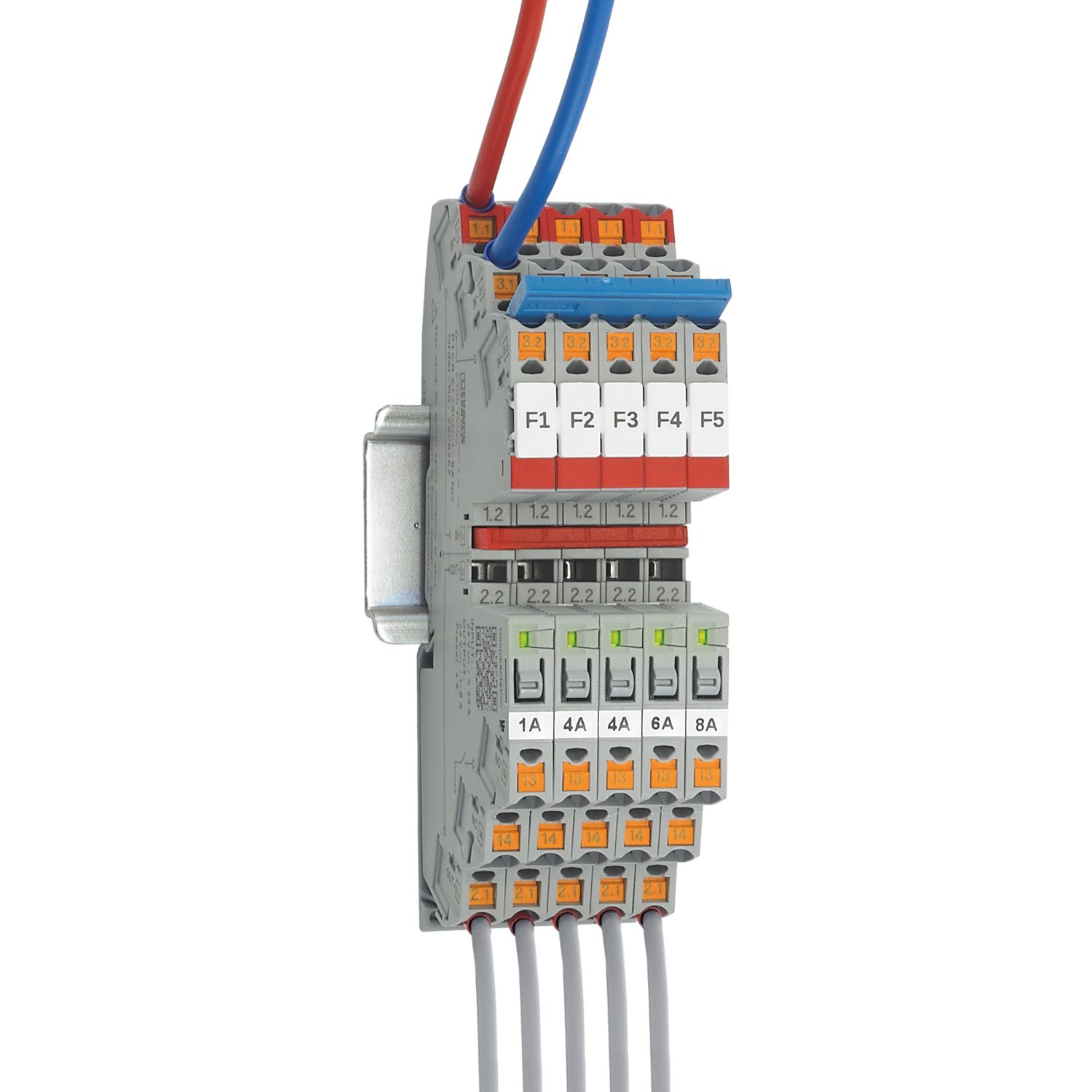
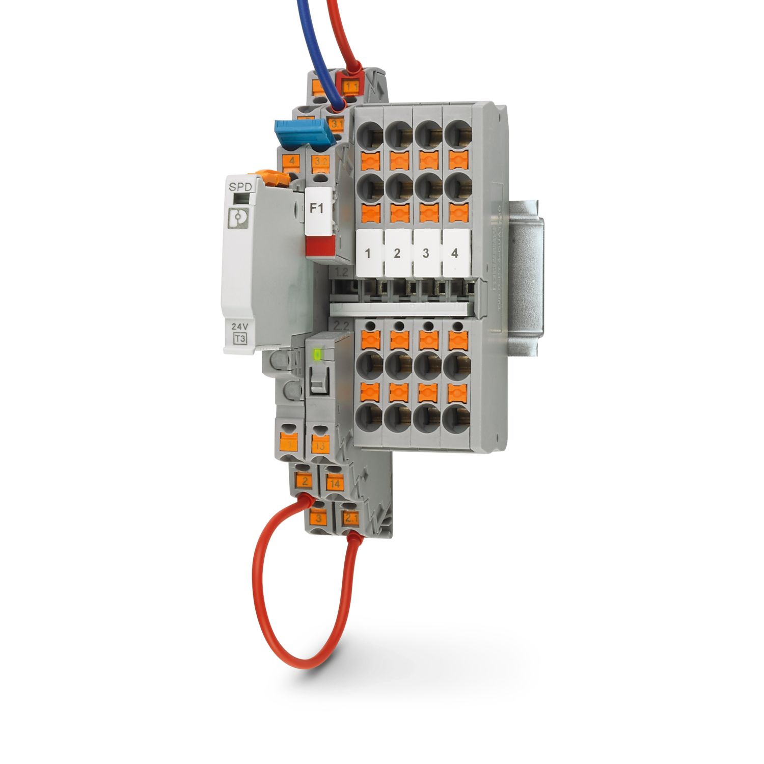
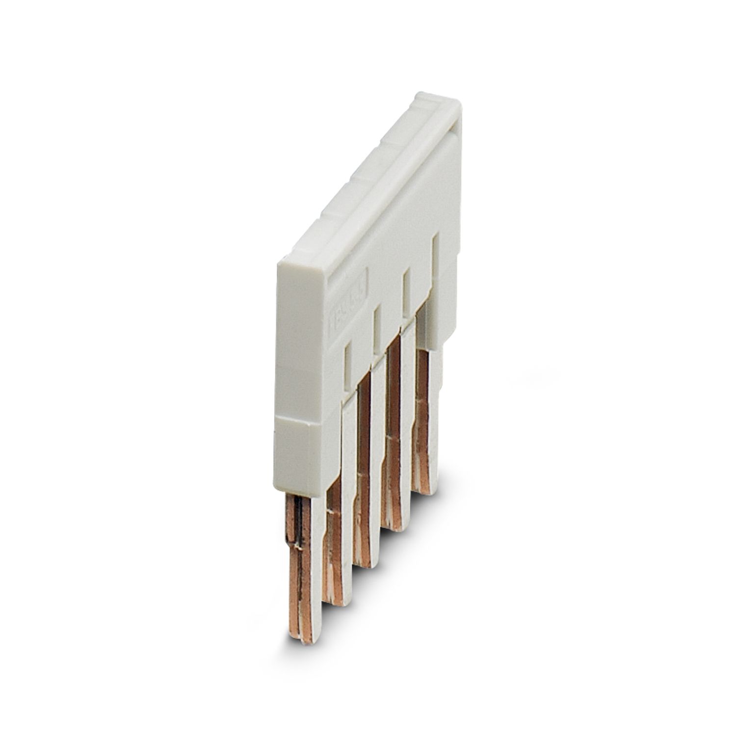
Simple application setup due to bridging option to CLIPLINE complete terminal block system
More space in the control cabinet: narrowest protection on just 6 mm width
Flexible use and reduction of inventory due to adjustable amp values on each device for wide range of applications
Individual setup for suitable protection, exactly according to your requirements
Optimum protection for cables and sensors as well as NEC Class 2 circuits by means of an additional internal output fuse
Frequently asked questions
Is there a hardware tutorial that explains the functions of the PTCB?
How do you set the nominal current?
1. Start the programming mode by pressing the LED button for > 2 seconds. The LED shows the set nominal current via a yellow flashing rhythm, e.g., 4 flashes for 4 A.
2. Set the required nominal current by pressing the button several times, e.g...
View more
1. Start the programming mode by pressing the LED button for > 2 seconds. The LED shows the set nominal current via a yellow flashing rhythm, e.g., 4 flashes for 4 A.
2. Set the required nominal current by pressing the button several times, e.g., 3 x for 3 A, then this is indicated by 3 x flashing.
3. Press the channel button for > 2 seconds to confirm the new current value.
If there is no confirmation, the channel exits programming mode after 60 seconds.
What signals does the PTCB offer?
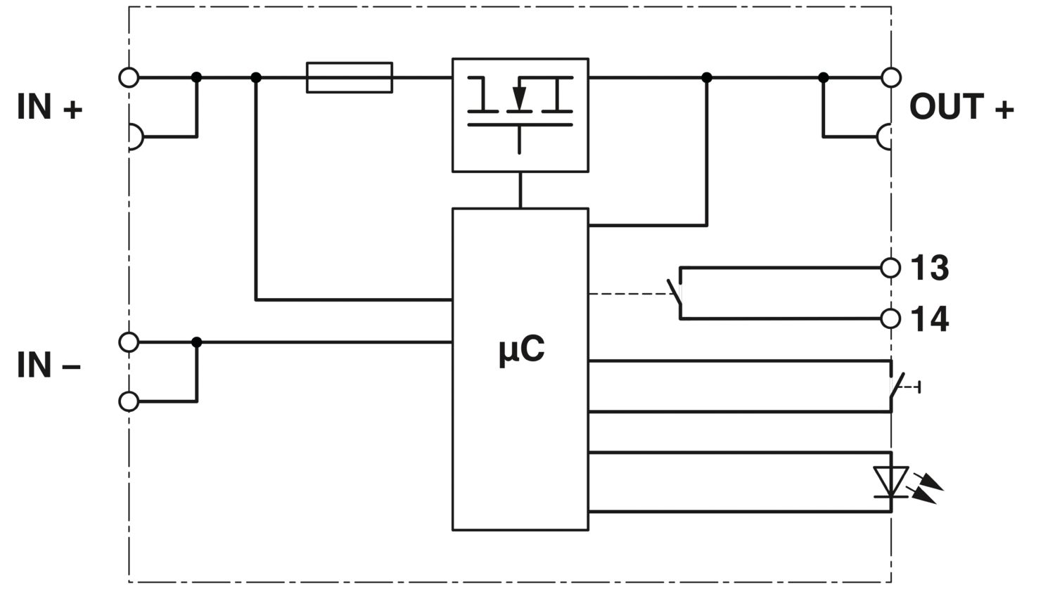
There are different versions of the PTCB, with 13-14 potential-free contacts (NO/NO2) or with a combination of reset input and status output (SI-R)
NO - potential free remote contact 13-14
This indicates the status of the PTCB. If there is...
View more
There are different versions of the PTCB, with 13-14 potential-free contacts (NO/NO2) or with a combination of reset input and status output (SI-R)
NO - potential free remote contact 13-14
This indicates the status of the PTCB. If there is a fault shutdown, it issues a message.
closed = there is no fault
open = there is a fault shutdown
With the NO2, the contact is also opened when the channel is switched off manually.
SI - status output
Potential-bound status signal which reflects the inverse status of the PTCB. If there is a fault shutdown, it issues a message.
High (24 V) = there is a fault shutdown
Low (0 V) = there is no error
Maximum current 20 mA
RST - reset input
The channel that was switched off by an error is switched on again via a falling edge.
What is the maximum current for a short circuit?
The maximum current depends on the available current that the power supply unit can supply in the event of a short circuit and the type of short circuit. The current is not limited by the PTCB.
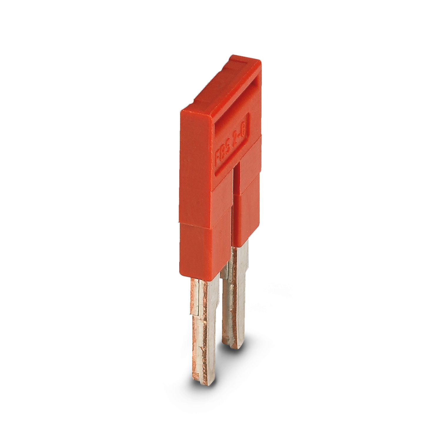
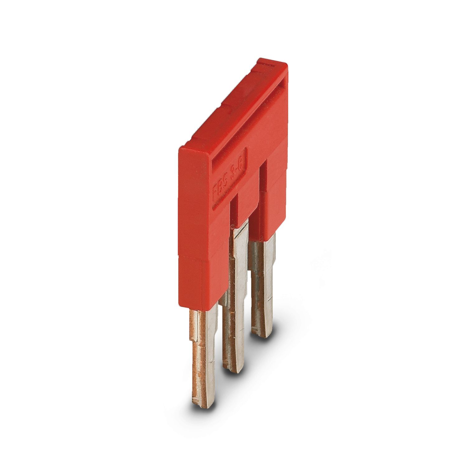
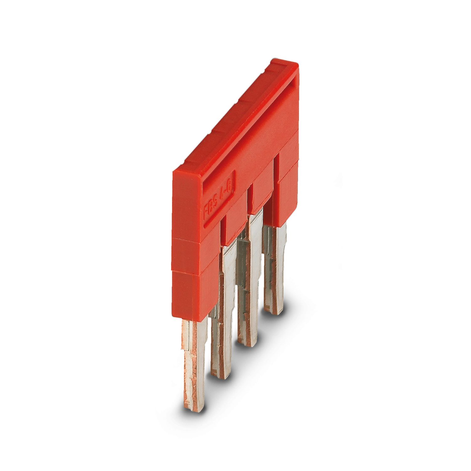
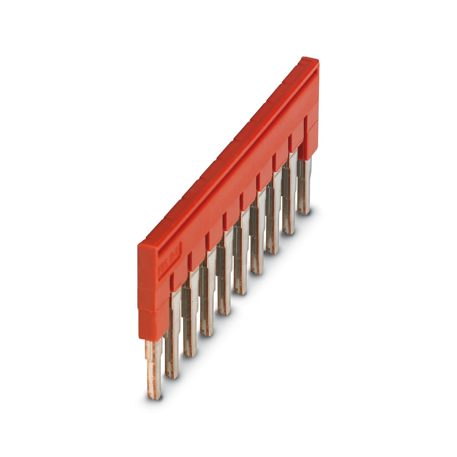
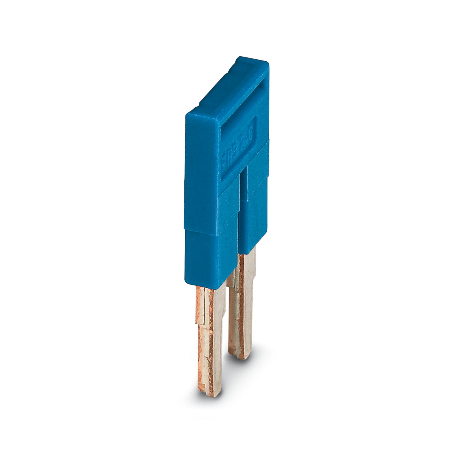
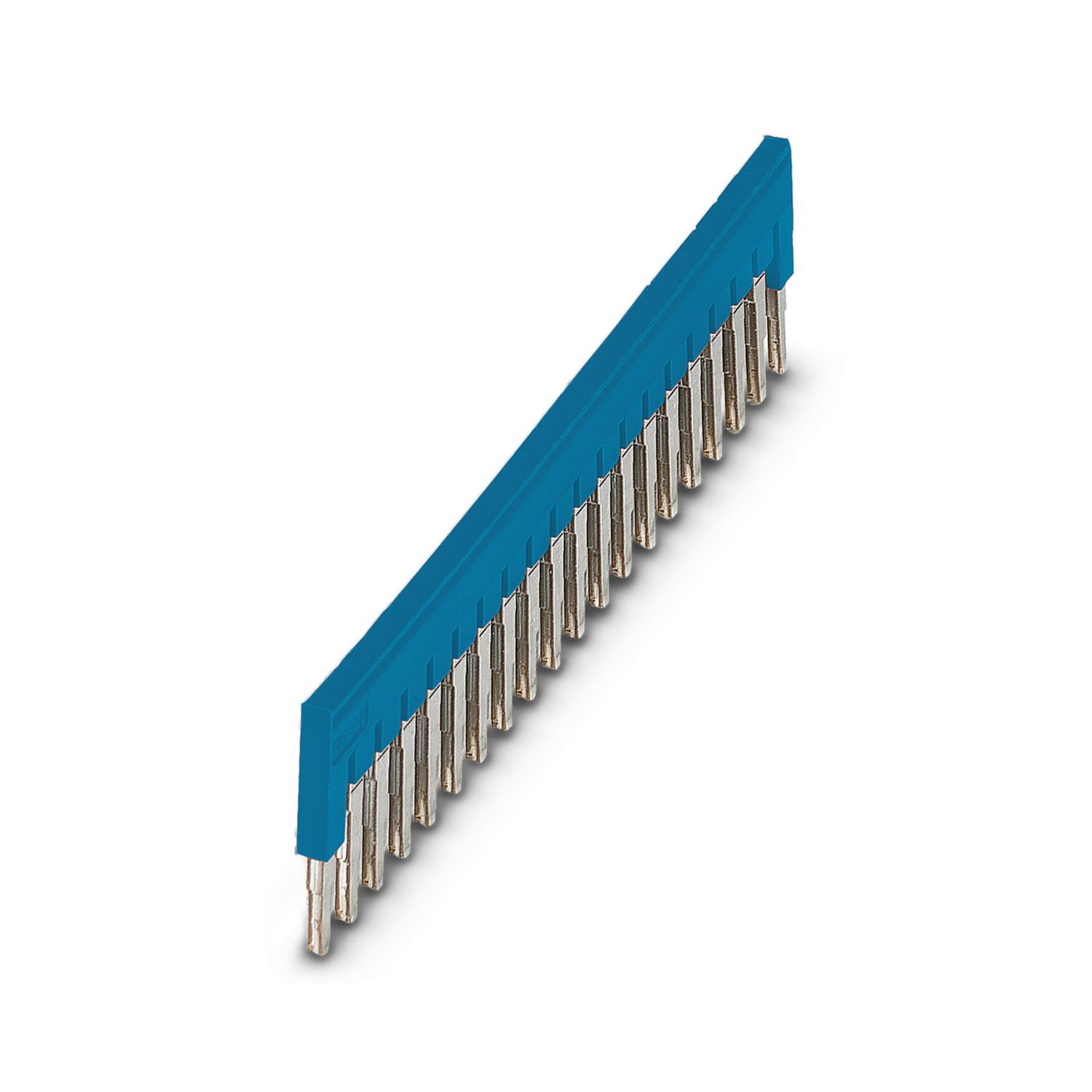
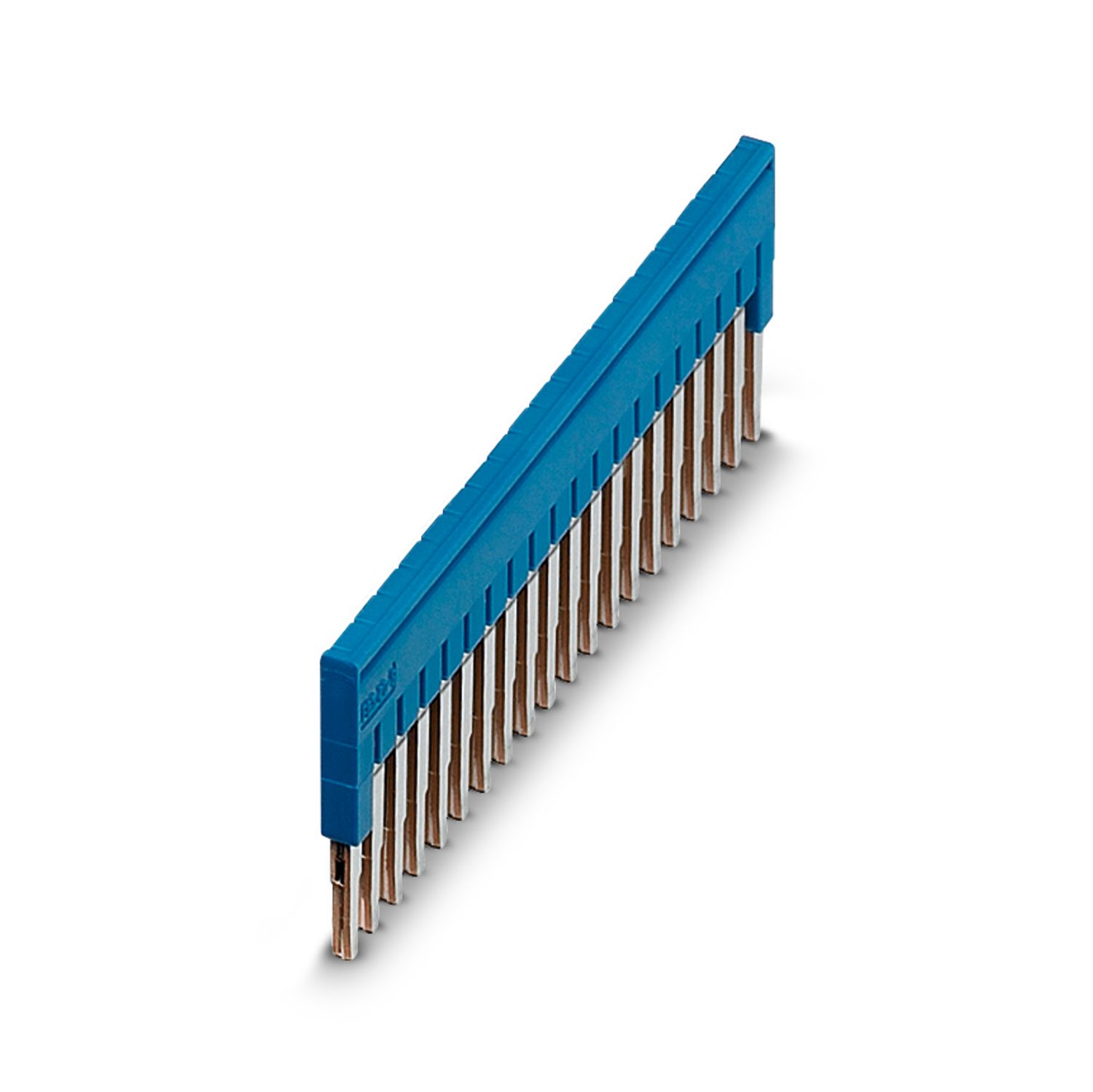
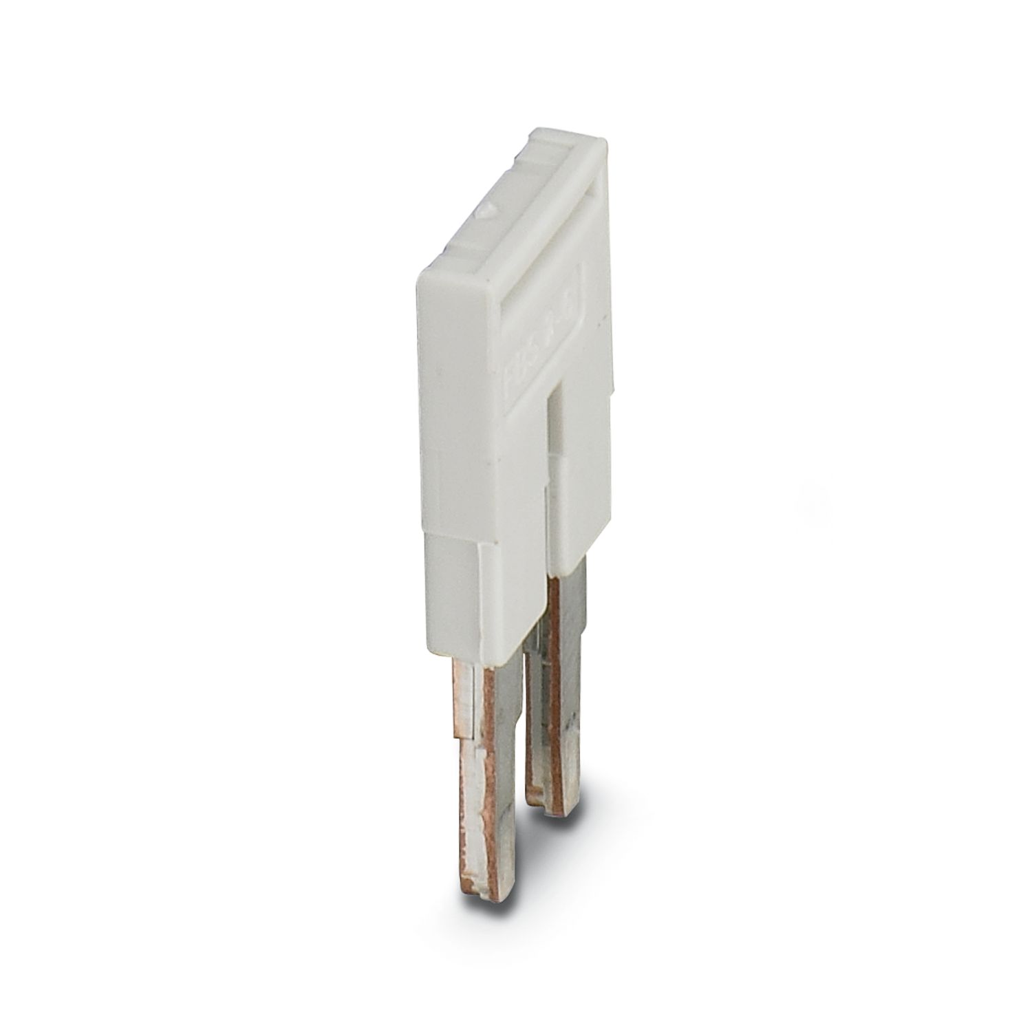
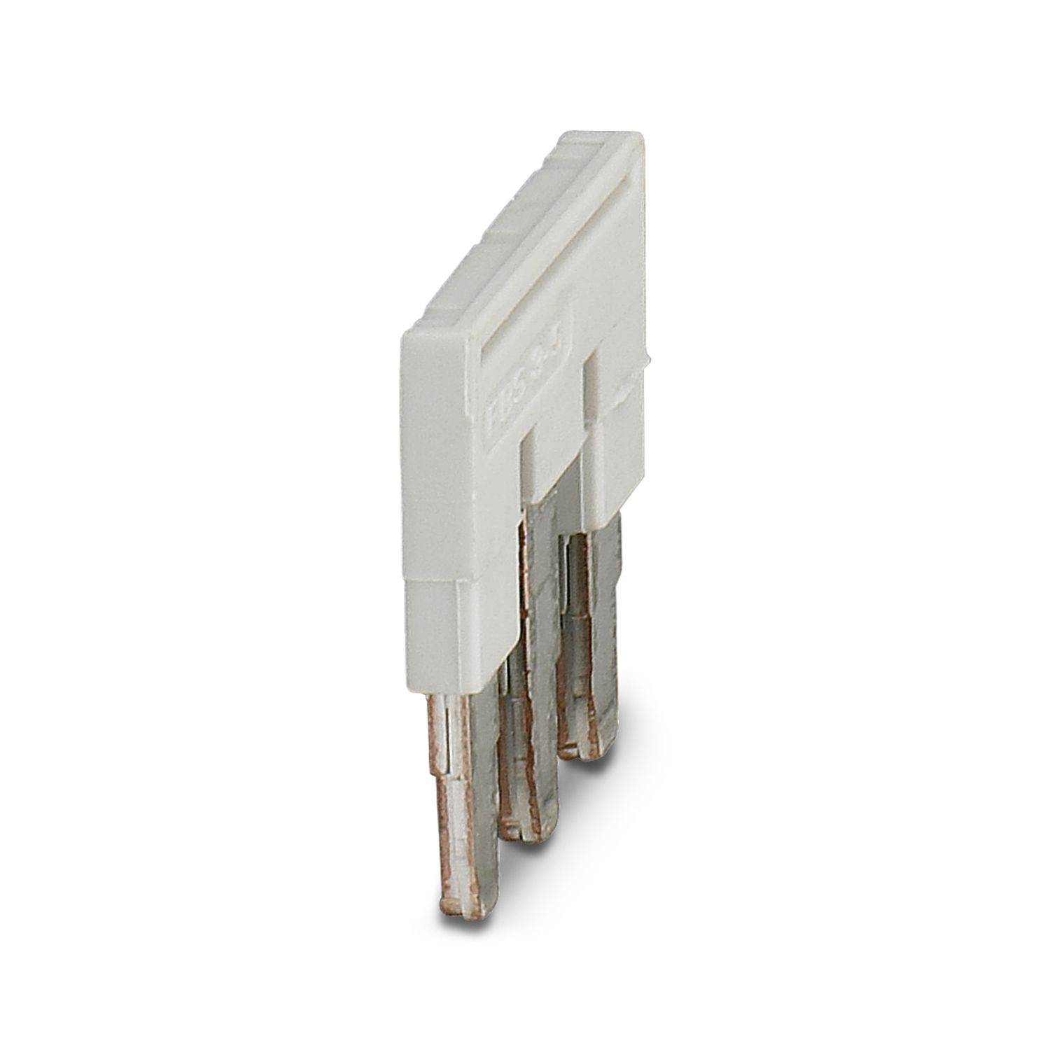
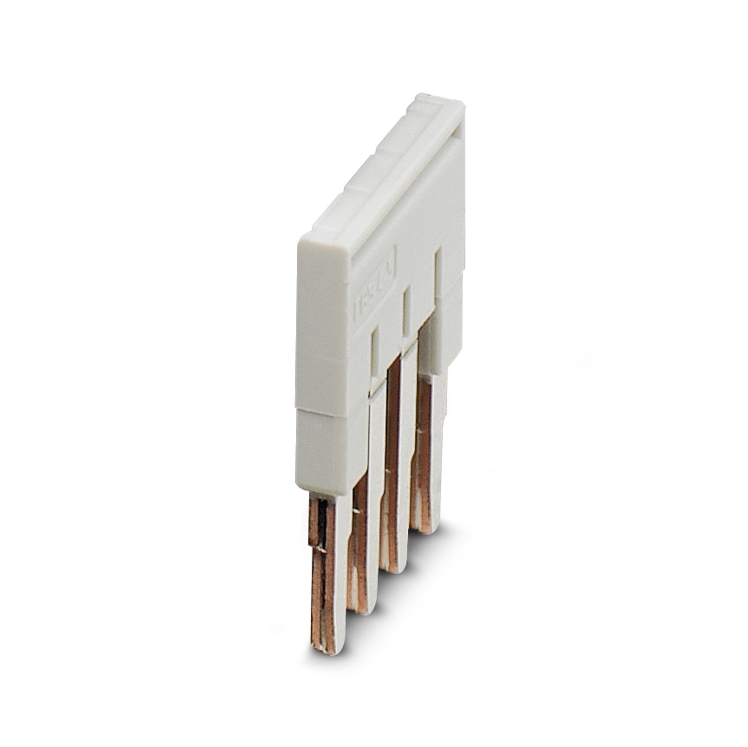
How many PTCBs can be bridged together?
The limitation of the PTCBs that can be bridged together is not due to the PTCBs, but to the bridges. The bridges can carry a maximum current of 32 A and the largest bridge has 50 poles. With a corresponding current, up to 50 PTCBs could therefore be bridged.
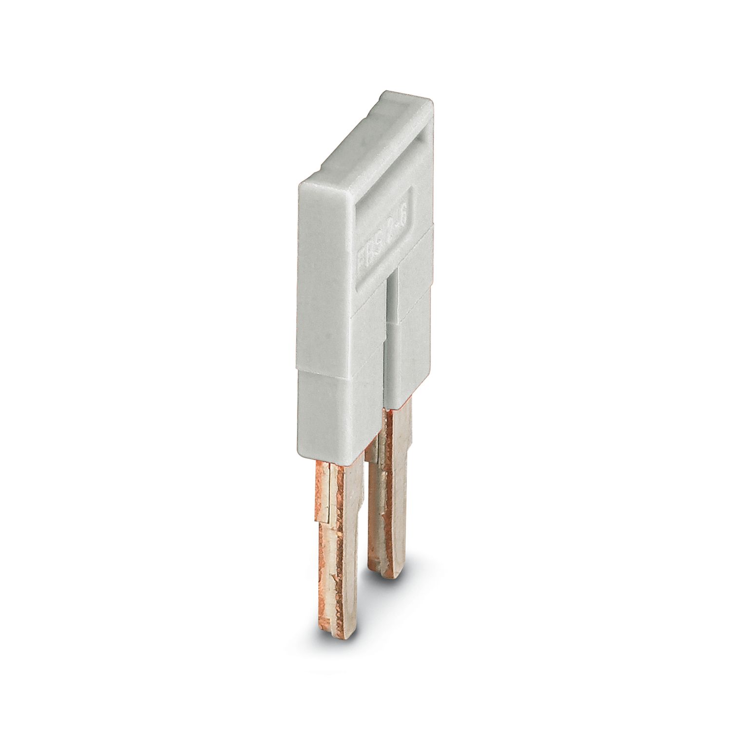
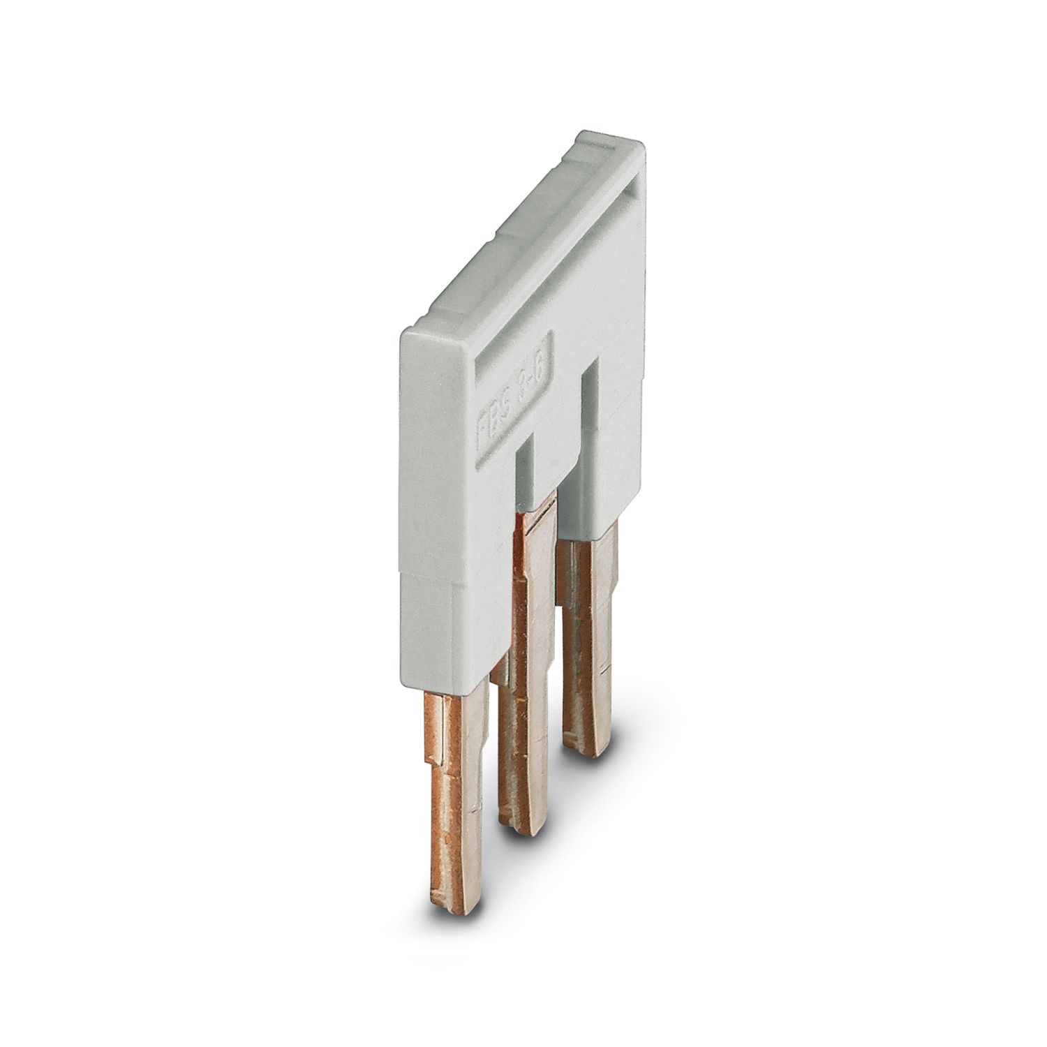
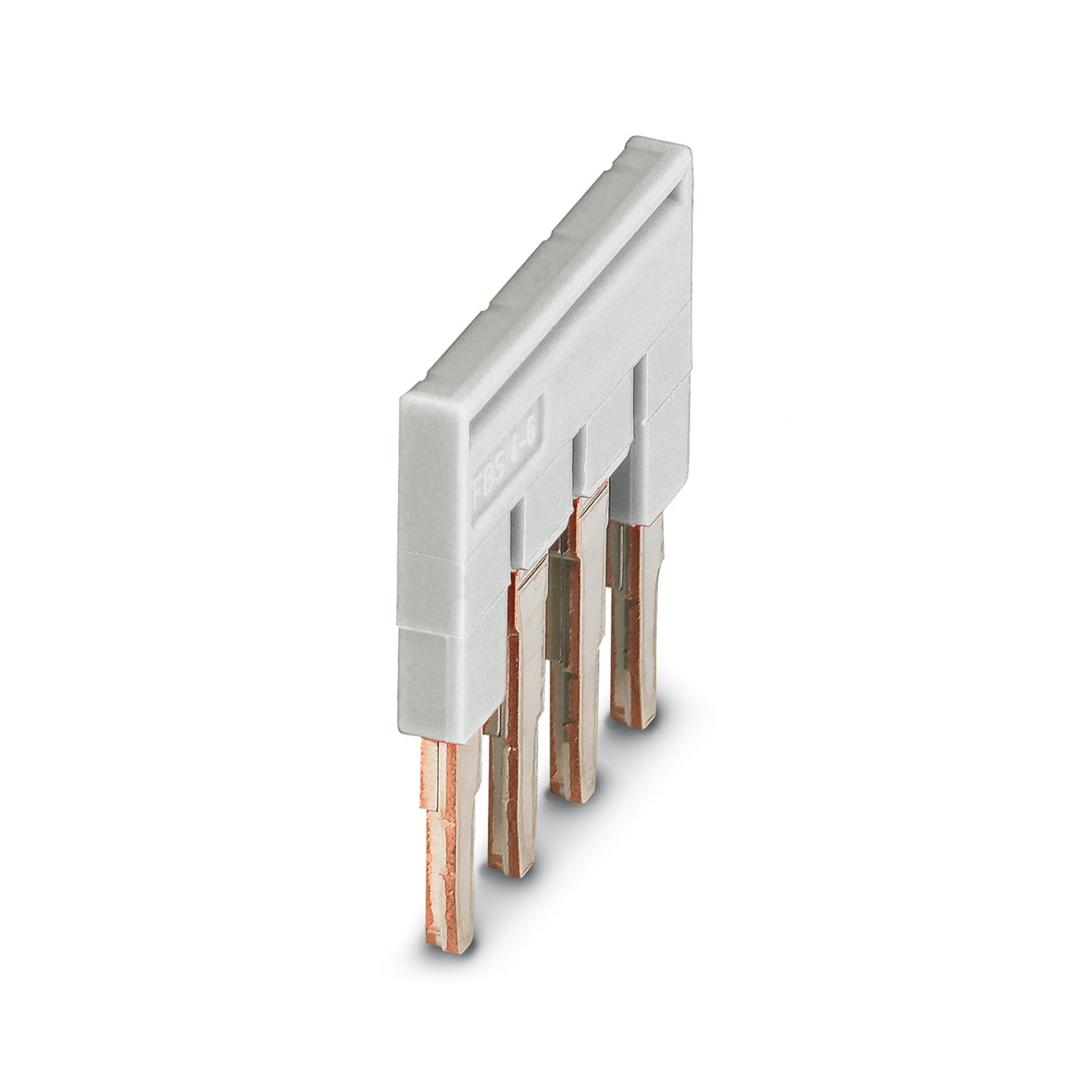
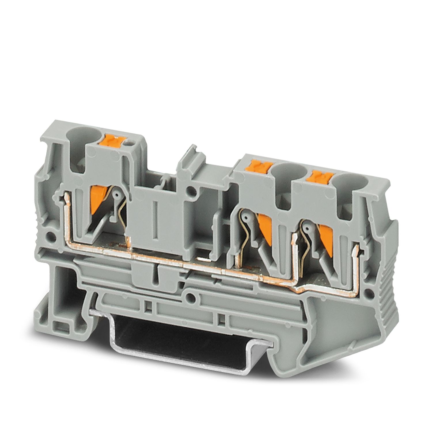
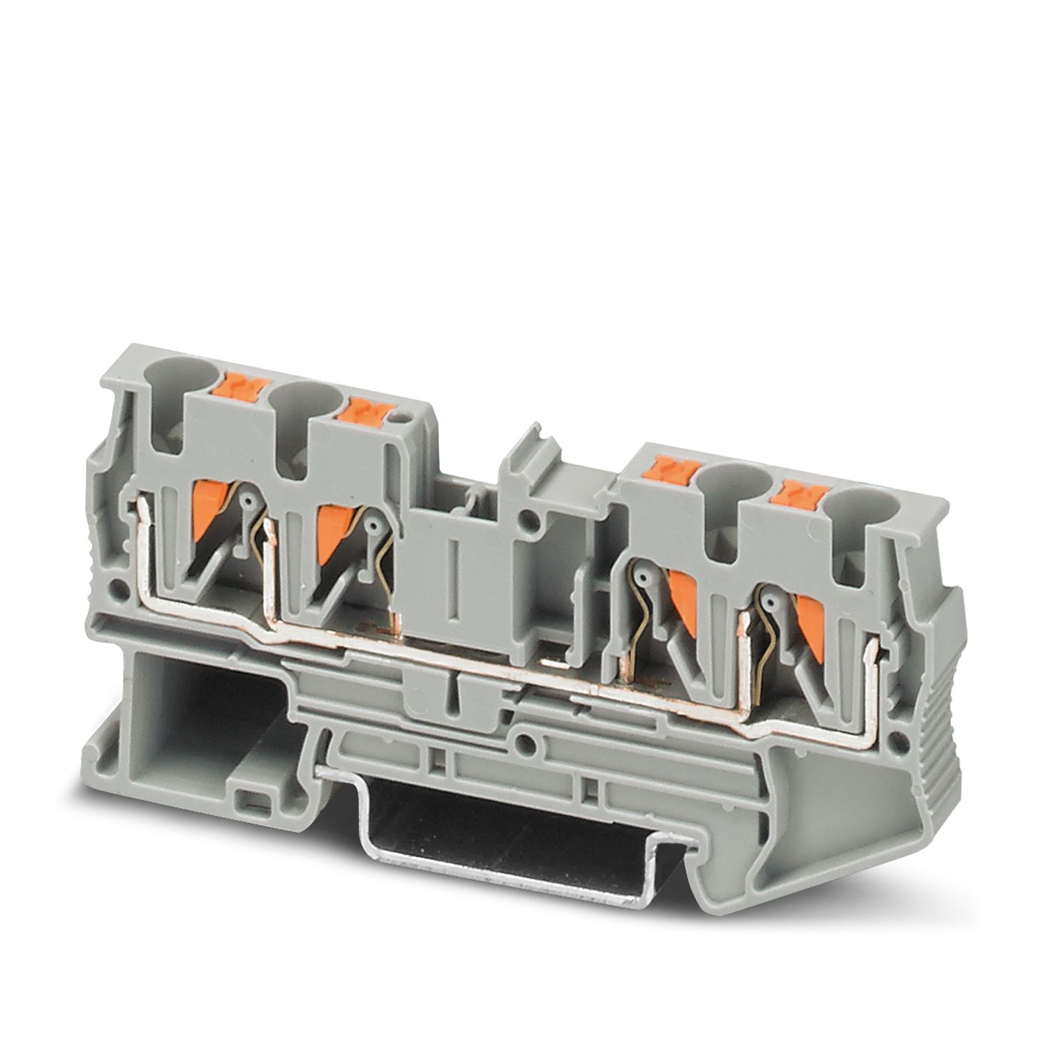
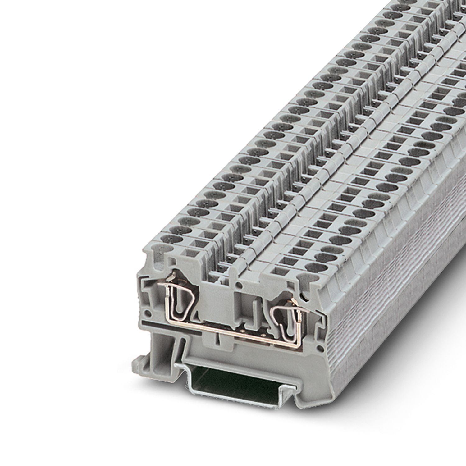
With which terminal blocks is the PTCB compatible?
The PTCB is compatible with the entire CLIPLINE complete portfolio, so that a corresponding terminal block can be used depending on the requirements. The corresponding bridges are also part of the CLIPLINE complete terminal block portfolio. A selecti... View more
The PTCB is compatible with the entire CLIPLINE complete portfolio, so that a corresponding terminal block can be used depending on the requirements. The corresponding bridges are also part of the CLIPLINE complete terminal block portfolio. A selection of compatible products (and associated bridges) can be found in the accessories tab on the product page.
View less