Conditioning and protection of digital and analog process signals

Interference-free signal transmission plays a central role in measurement and control technology (MCR technology). Signal transmission is affected by an increasingly active electrical environment. This holds especially true for the weak measured value signals emitted by sensors. Insufficient attention given to the above disturbance variables, incorrect adjustments, or any other lack of planning can all affect interference-free signal transmission.
Signal types and signal conditioning

What signals are we talking about?
Analog signals are electrical voltage and current signals. To map a changing physical variable, a sensor can either generate an electrical voltage or change the voltage drop in the measuring circuit.
Typically, the following variables are measured in system and process technology:
- Temperature
- Pressure
- Level flow rate
- Vibration
- Deformation with regard to load measurement
- Humidity
- Gas concentration
- Electrophysical variables such as voltage, current, field strength, etc.
Stations for measuring signal conditioning
The electrosensory acquisition, conditioning, and evaluation of status data referring to the environment or an industrial system are considered to be the core areas in the field of MCR technology.
These three areas are the main focus:
- Signal generation in the field, as the monitored area to be controlled is called
- Signal conditioning at the interface level or directly at the field level by means of electronic components for amplification, conversion, and protection from interference on the signal path
- Analog or digital signal processing at the control level by an evaluation or control unit.

Analog signal from the sensor to the controller
Signal conditioners and measuring transducers

Functions of signal conditioners and measuring transducers
The electronic blocks for signal conditioning are collectively referred to as signal conditioners, signal isolators, or measuring transducers.
The devices can have one or more of these functions:
1. Signal amplification
Signal amplification is always required if a signal is too weak and can therefore only be acquired by the connected evaluation unit in a distorted or attenuated form.
Example:
Without the amplifier, the load connected to the measuring sensor would be 320 Ω and therefore higher than the maximum permissible load of 300 Ω. The measuring sensor is not able to drive this load, which would result in a distorted measuring signal.
By adding an amplifier, the load connected to the measuring sensor is 70 Ω and thus lower than the maximum permissible load of 300 Ω. Furthermore, the input resistance of the evaluation unit, which is 300 Ω, does not overload the amplifier output, as it is intended to drive a load of up to 500 Ω. The measuring signal will not be distorted.

Beispiel Signalverstärkung zur Fehlerbeseitigung
2. Conversion to a standard signal
Depending on the measuring task, analog sensor signals can be converted into one of the standard signals in an interface block. The conversion result should be proportional to the measured input value to avoid distorting the measurement results.
Example:
The sensor or transmitter provides a standard signal of 4 to 20 mA. The evaluation unit requires a 0 to 10 V signal. The standard signal converter connected between the transmitter and the evaluation unit makes the required adjustment.

Conversion to a standard signal example
3. Filtering
In cables for measured value transmission, interference voltages can occur, for example, due to effects such as electromagnetic induction or high-frequency signals like those generated by frequency converters in industrial environments. Interference is particularly strong if voltage signals are affected.
Example:
The signal conditioner with filter function detects and suppresses interference voltages in a wide frequency spectrum.
It is also helpful to use additional twisted or shielded cables. Twisted cables help to reduce the induced interference voltage, while shielded cables additionally reflect and absorb electric fields. To further avoid interference resulting from the causes mentioned above, the voltage signal should be converted into a current signal.

Signal filtering example
4. Electrical isolation
An electrically isolated signal connection is referred to as a floating connection because there are no compensating currents flowing between potential differences. Electrical isolation of field circuits and control circuits has become an established standard in the plant and process industry.
Example:
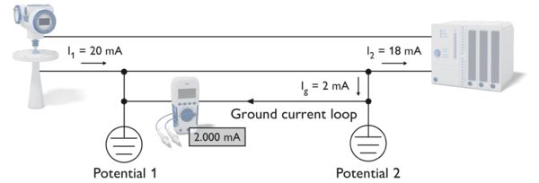
The problem: The transmitter and evaluation unit are grounded, but have different ground potentials. A compensating current Ig flows through the resulting ground current loop and thus distorts the measuring signal I1.

Ground current loop example
After integrating a galvanic signal isolator, such as a transmitter, into the connecting cables for the measuring signal, the lg compensating current no longer flows. The measured signal is I2, which is identical to the measured signal I1.

Electrical isolation, no ground current loop example
5. Line monitoring
Line monitoring is integrated in many interface blocks as an additional function. The monitoring function for line interruptions and short circuit is specified in greater detail in the NE 21 NAMUR recommendations provided by the User Association of Automation Technology in Process Industries.
Example:
The figure shows schematically how line monitoring can be used on the entire signal transmission path from the sensor to the evaluation unit.
The 400 to 2 kΩ resistance ensures a maximum current with closed switch that is less than the short-circuit current. The 10 kΩ resistance provides a closed-circuit current when the switch is open. In the event of a line break, the current = 0.

Line monitoring example
Supply and isolation of signal paths
Electrical supply and isolation of signal paths
Depending on whether the connected sensor or transmitter has its own power supply or is supplied via sensor signal cables, there is a difference made between a passive and active input at the input terminals of a signal conditioner or evaluation unit.
Passive input
The only function of the passive signal input is to receive the signal.
Example:
In the example, the signal conditioner and the evaluation unit have passive inputs. The active sensor or transmitter (with four connections) supplies the passive input of the signal conditioner. The active output of the signal conditioner supplies the passive input of the evaluation unit.

Example for an passive signal input
Active input
The active signal input has two functions: one is to receive the signal, and the other is to supply power to the signal generator.
Example:
In the example, the signal conditioner has an active input. It supplies the 2- or 3-conductor sensor or transmitter. The active output of the signal conditioner supplies the passive input of the evaluation unit (as in the previous example). Components that need an electric power source can be supplied by separate power supplies or via the signal lines.

Active signal input example
Passive isolation, input loop-powered
Signal conditioner supply via a signal input through the transmitter (input loop-powered). Only suitable for 4 to 20 mA signals.
Example:
The signal paths between the active sensor/transmitter (4-conductor connection) and the signal conditioner are not isolated from the transmitter supply here. In this case, the active sensor/transmitter takes over the supply of the signal conditioner.
The sensor/transmitter needs to drive the total load of the signal conditioner and the evaluation unit input.

Example for passive isolation, input loop-powered
Passive isolation, output loop-powered
In this case, the signal conditioner is supplied via the signal output through the evaluation unit (output loop-powered). Only suitable for 4 to 20 mA signals.
Example:
The signal path between the sensor/transmitter (4-conductor connection) and signal conditioner is isolated from the transmitter supply.
The signal path between the signal conditioner and evaluation unit is not isolated from the evaluation unit supply. In this case, the evaluation unit takes over the supply of the signal conditioner.

Example of passive isolation, output loop-powered


