
CAPAROC E2 12-24DC/1-4A
-
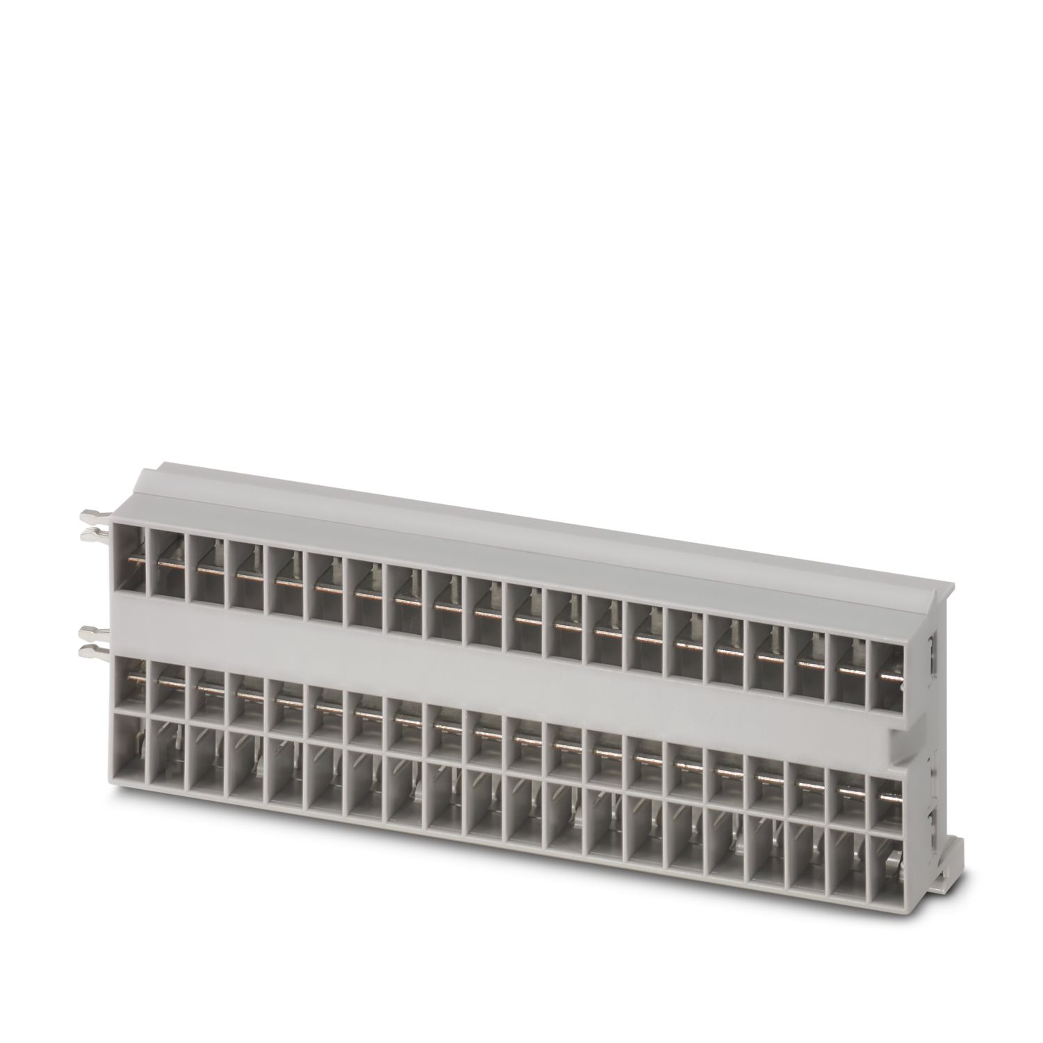
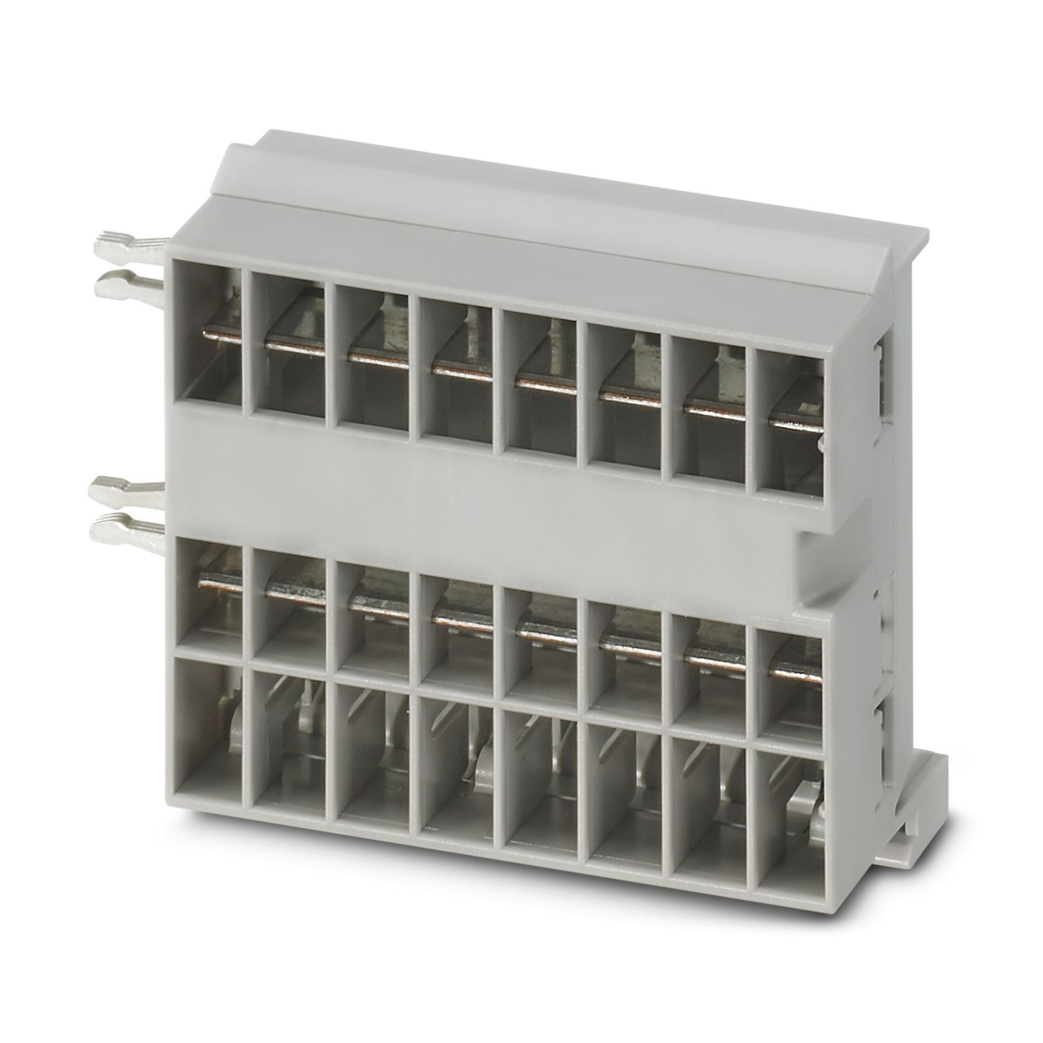
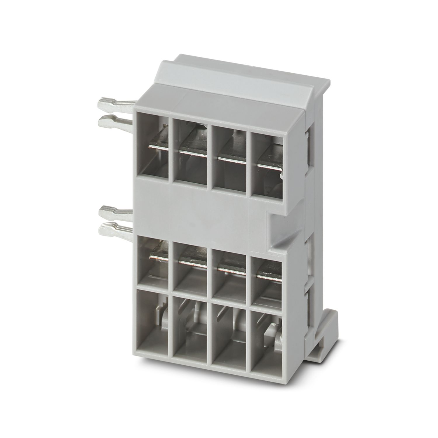
Electronic circuit breaker
1115655
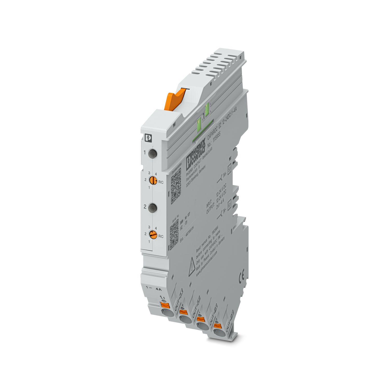

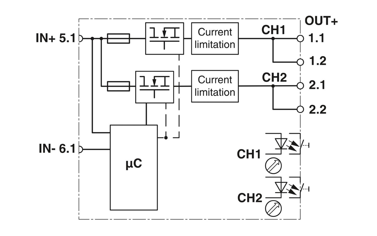

2-channel electronic circuit breaker module for protecting loads at 12 and 24 V DC against overload and short circuit with current limit. Nominal current adjustable from 1 A to 4 A using step switch. For DIN rail installation via the CAPAROC current rails.
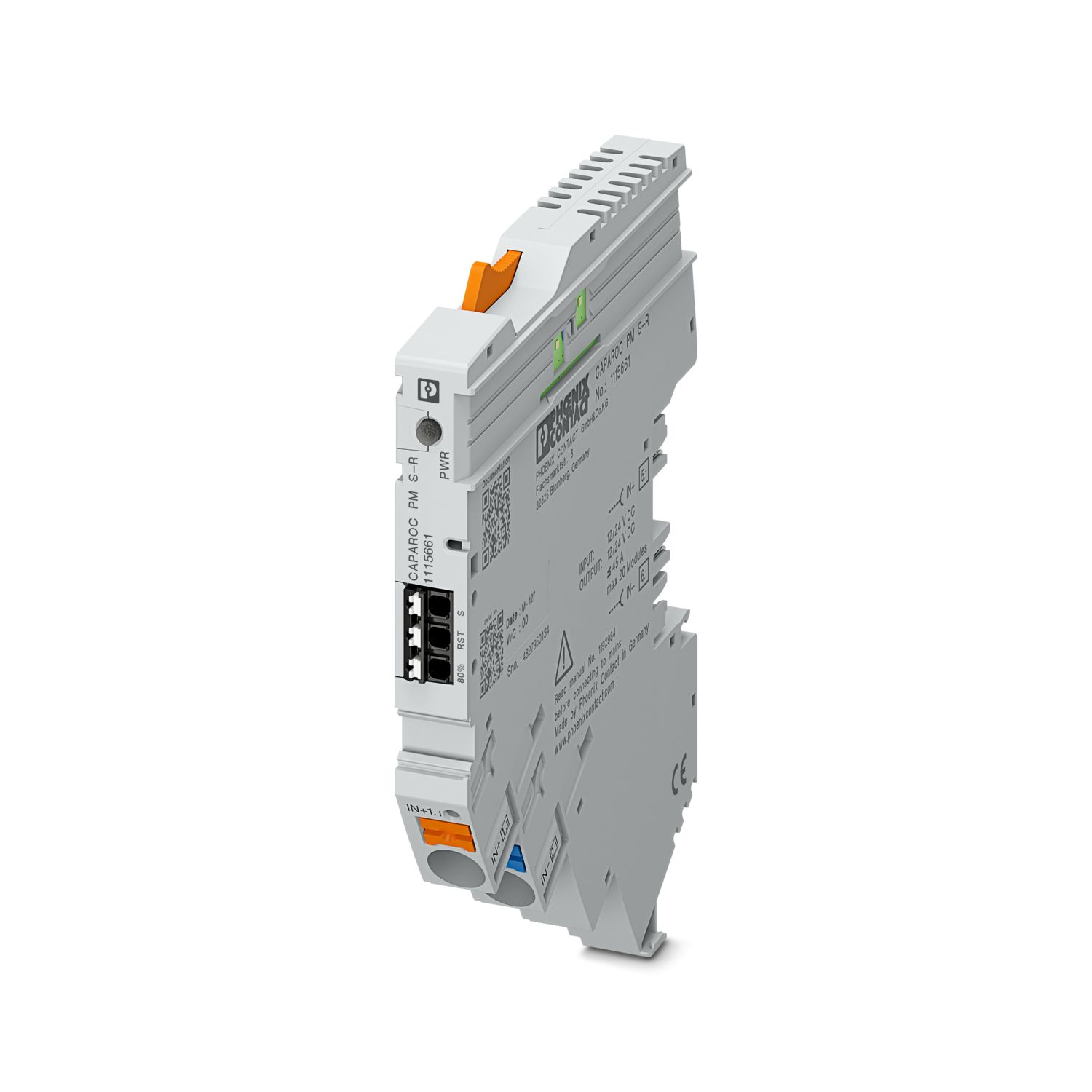
This product needs further products for operation.
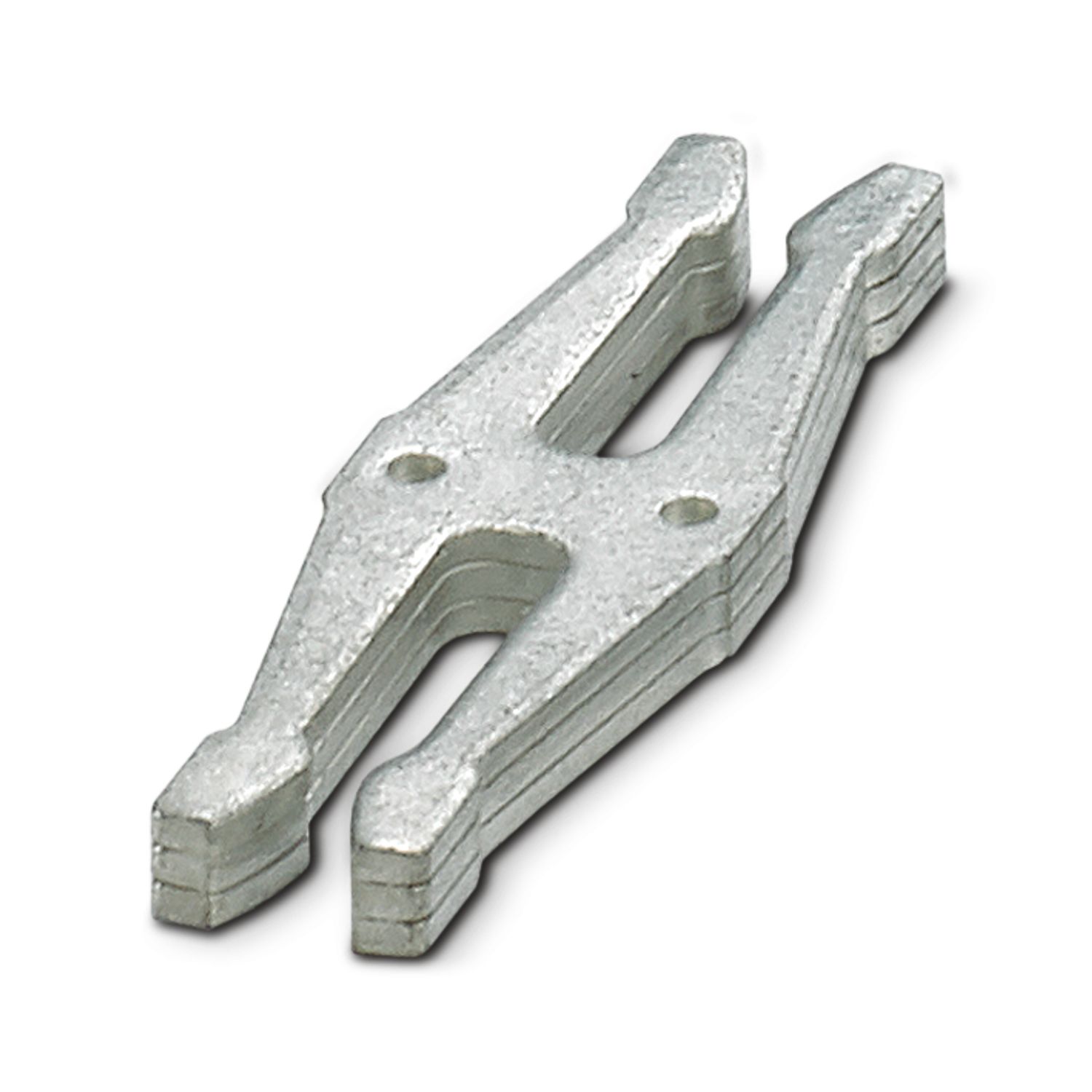
Mandatory accessories
Product details
| General | |
| Note | LABS release – in accordance with test specification VW PV 3.10.7:2005-0 |
| When connecting the conductor, make sure that the CAPAROC modules are not pulled apart due to tensile force. Gaps must not be created between the modules. | |
| Product type | Device circuit breakers |
| Product family | CAPAROC |
| Type | Plug-in module |
| Number of positions | 1 |
| No. of channels | 2 |
| Number of slots | 2 |
| Insulation characteristics | |
| Protection class | III |
| Pollution degree | 2 |
| General | |
| Operating voltage | 10 V DC ... 30 V DC |
| Rated voltage | 12 V DC |
| 24 V DC | |
| Rated current IN | 4 A (per channel) |
| Rated current IN | 1 / 2 / 3 / 4 A DC (Adjustable via rotary coding switches) |
| 1 / 2 / 3 / 4 A DC (can be set, in RC mode via power module with communication interface) | |
| Rated current (pre-adjusted) | 1 A |
| Rated surge voltage | 0.5 kV |
| Tripping method | E (electronic) |
| Feedback resistance | max. 35 V DC |
| Switch-on delay | 50 ms (each channel preset by default) |
| can be adapted with CAPAROC PM IOL and CAPAROC PM PN power modules | |
| Required backup fuse | Only required if Imax of the power supply > the short-circuit switching capacity. Integrated failsafe element. |
| Short-circuit switching capacity | 300 A |
| Dielectric strength | 35 V DC (Load circuit) |
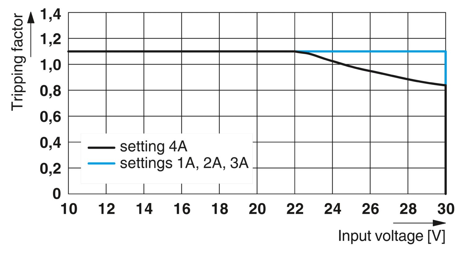
| Active current limitation | typ. 2.0 x IN at IN ≤ 3 A |
| typ. 1.5 x IN at IN = 4 A | |
| Fuse | electronic |
| Efficiency | > 99 % |
| Closed circuit current I0 | typ. 25 mA (no load at 24 V) |
| Power dissipation | typ. 0.6 W (no load at 24 V) |
| < 1.1 W (in nominal operation at 24 V and 4 A) | |
| Measuring tolerance I | ± 10 % (2 A ... 4 A) |
| ± 20 % (1 A) | |
| MTBF (IEC 61709, SN 29500) | 11364927 h (at 25 °C with 21 % load) |
| 5271554 h (at 40°C with 34.25% load) | |
| 640731 h (at 65°C with 100% load) | |
| Voltage drop | 0.06 V (at 4 A) |
| Fail-safe element | 5 A DC (per output channel) |
| Contact switching type | without electrical isolation |
| Load circuit | |
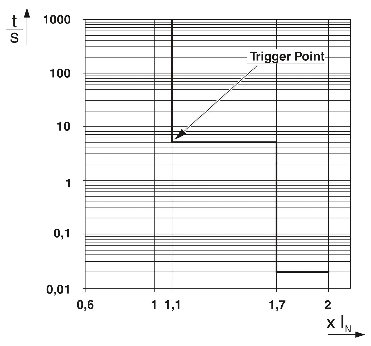
| Shutdown time | 5 s (with overload 1.1…1.3 x IN at IN ≥ 4 A) |
| 5 s (for overload 1.1…1.7 x IN at IN < 4 A) | |
| ≤ 400 ms (max. 450 ms for high starting currents) | |
| typ. 20 ms (for short circuit > 1,5 x IN) | |
| Undervoltage switch-off | ≤ 8.5 V DC (active) |
| ≥ 9.2 V DC (inactive) | |
| Overvoltage switch-off | ≥ 32.5 V DC (active) |
| ≤ 30.5 V DC (inactive) | |
| Max. capacitive load | ≤ 60000 µF (Depending on the current setting and the short-circuit current available) |
| Fuse-protected output | |
| Connection method | Push-in connection |
| Stripping length | 10 mm |
| Conductor cross-section flexible | 0.2 mm² ... 4 mm² |
| Conductor cross-section rigid | 0.2 mm² ... 4 mm² |
| Conductor cross-section AWG | 24 ... 12 |
| Conductor cross-section, flexible, with ferrule, with plastic sleeve | 0.25 mm² ... 4 mm² |
| Conductor cross-section, flexible, with ferrule, without plastic sleeve | 0.25 mm² ... 4 mm² |
| Channel LED off | off (Channel switched off) |
| Channel LED yellow | lit (Channel switched on, channel load > 80% ) |
| two flashes (Check the installation, no communication to power module) | |
| Channel LED green | lit (Channel switched on) |
| flashing (Channel switched on, coding switch position is not equal to set value) | |
| Channel LED red | lit (Channel switched off, over- or undervoltage active) |
| ON temporarily (Channel switched off, 5 s cool-down phase, overload or short-circuit release) | |
| flashing (Channel switched off, ready to be switched back on, overload or short-circuit release) | |
| two flashes (Channel switched off, system total current limit exceeded) | |
| Channel LED red-yellow | flashing (Channel is overloaded and is switched off) |
| Channel LED red-green | flashing (Channel switched off, programming mode active, current adjustment after overload or short-circuit release) |
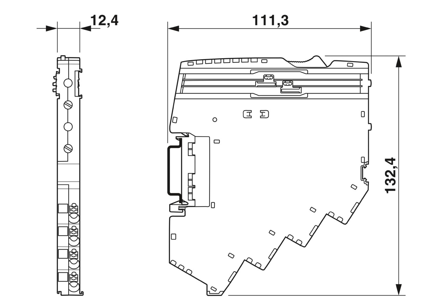
| Dimensional drawing |
|
| Width | 12.4 mm |
| Height | 132.4 mm |
| Depth | 111.3 mm (incl. DIN rail 7.5 mm) |
| Color | light gray (RAL 7035) |
| Material | PA 6 |
| PA 6 | |
| PA 6 | |
| PC | |
| Flammability rating according to UL 94 | V-0 |
| Ambient conditions | |
| Degree of protection | IP20 |
| Ambient temperature (operation) | -30 °C ... 65 °C (The temperature range of the power module must be taken into consideration) |
| Ambient temperature (storage/transport) | -40 °C ... 70 °C |
| Altitude | ≤ 4000 m (amsl) |
| Humidity test | 96 h, 95 % RH, 40 °C |
| Shock (operation) | 30g (11 ms period, half-sine shock pulse, according to IEC 60068-2-27) |
| 25g (6 ms duration, half-sine shock pulse in accordance with IEC 60068-2-27, continuous shock) | |
| Vibration (operation) | 5g (10 Hz ... 150 Hz / 10 cycles / axis / X, Y, Z) |
| UL approval | |
| Identification | UL/C-UL Listed UL 508 |
| UL Recognized UL 2367 | |
| UL 121201 Class I, Division 2, Groups A, B, C, D, T4A | |
| NEC Class 2 according to UL 1310 | |
| Corrosive gas test | |
| Identification | ISA S71.04.2013 G3 Harsh Group A |
| Standards/specifications | EN 61000-6-2 |
| Note | EMC – Immunity for industrial areas |
| Standards/specifications | EN 61000-6-3 |
| Note | EMC – Emission for residential, business and commercial properties and small operations |
| Standards/specifications | EN 60068-2-78 |
| Note | Environmental influences – Moisture and heat, constant |
| Standards/specifications | EN 50178 |
| Note | Equipping power installations with electronic equipment |
| Standards/specifications | EN 60068-2-6 |
| Note | Environmental influences – Vibrations (sinusoidal) |
| Standards/specifications | EN 60068-2-27 |
| Note | Environmental influences – Shocks |
| Mounting type | pluggable onto CAPAROC CR… current rail |


Your advantages
The benchmark that you can customize with convenient nominal current level setting on the module
Easy operation for everyone through tool-free assembly, uninterrupted installation, and transparent operating state
Exceptionally easy design-in allows the nominal current to be extended beyond the specified levels via PROFINET
Frequently asked questions
How many fused outgoing circuits do the circuit breaker modules have?
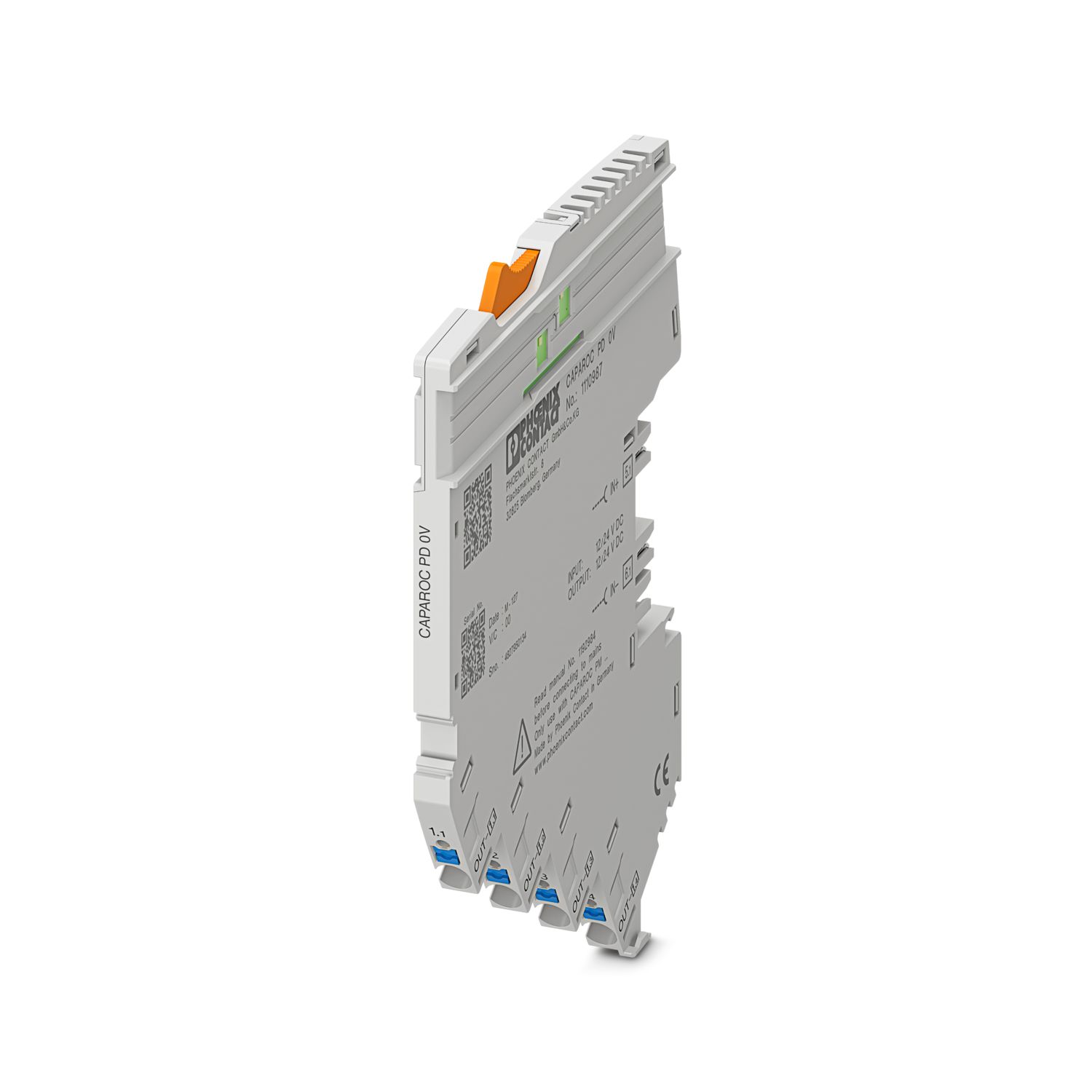
CAPAROC 1-channel modules have four connection points with the same fused potential.
CAPAROC 2-channel modules have two connection points per channel.
CAPAROC 4-channel modules have one connection point per channel.
Is there a hardware tutorial in which the CAPAROC functions are explained?
How many circuit breaker modules can I connect downstream of an infeed module?
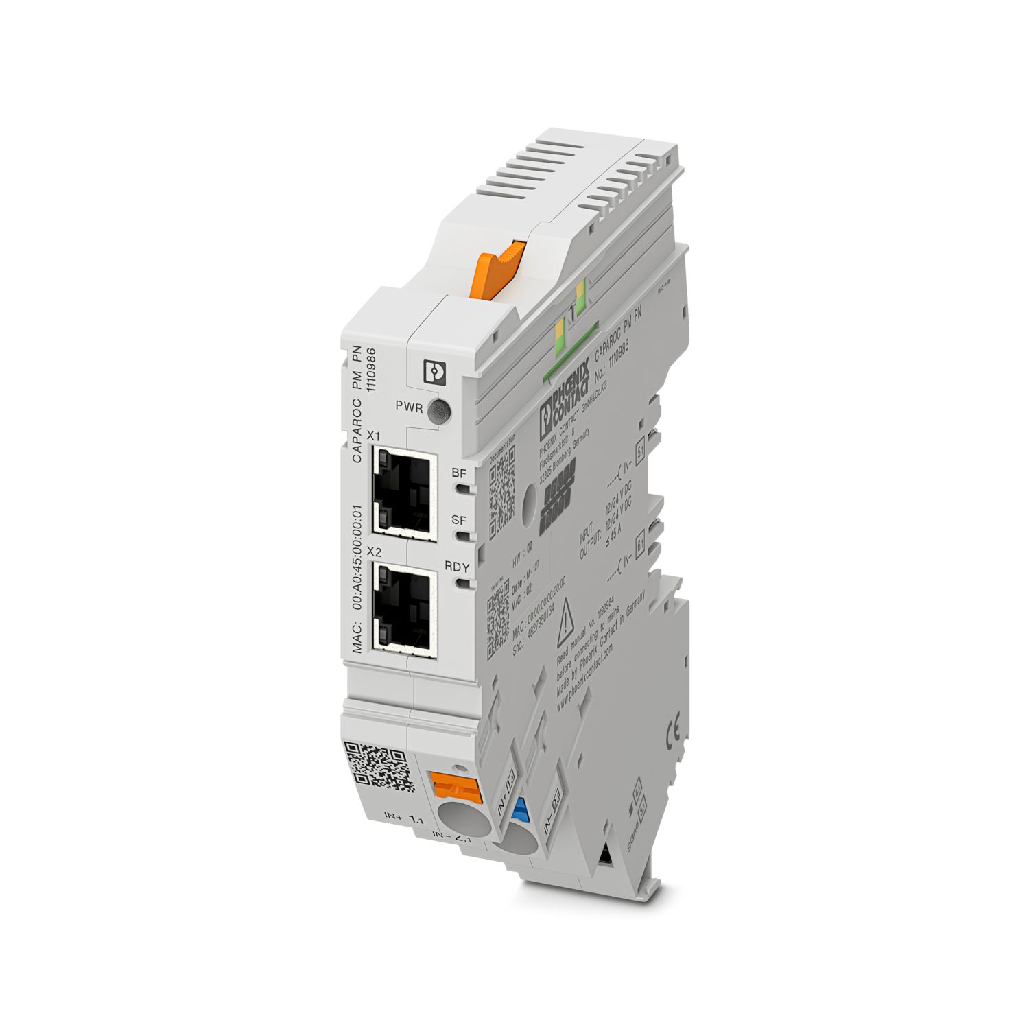
CAPAROC PM S-R: 20 circuit breaker modules
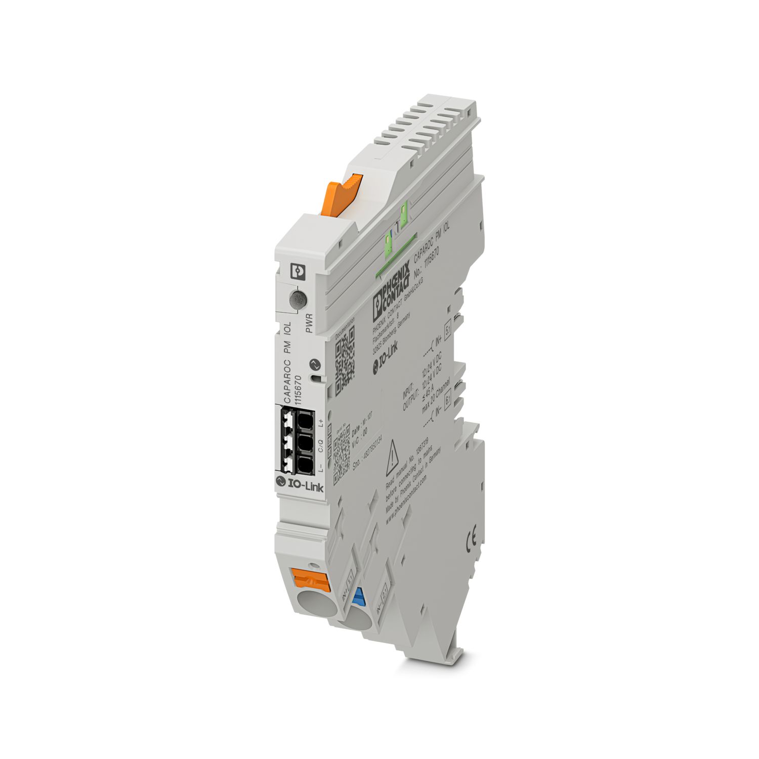
CAPAROC PM IOL: 20 channels
CAPAROC PM PN: 16 circuit breaker modules
CAPAROC PM EIP: 16 circuit breaker modules
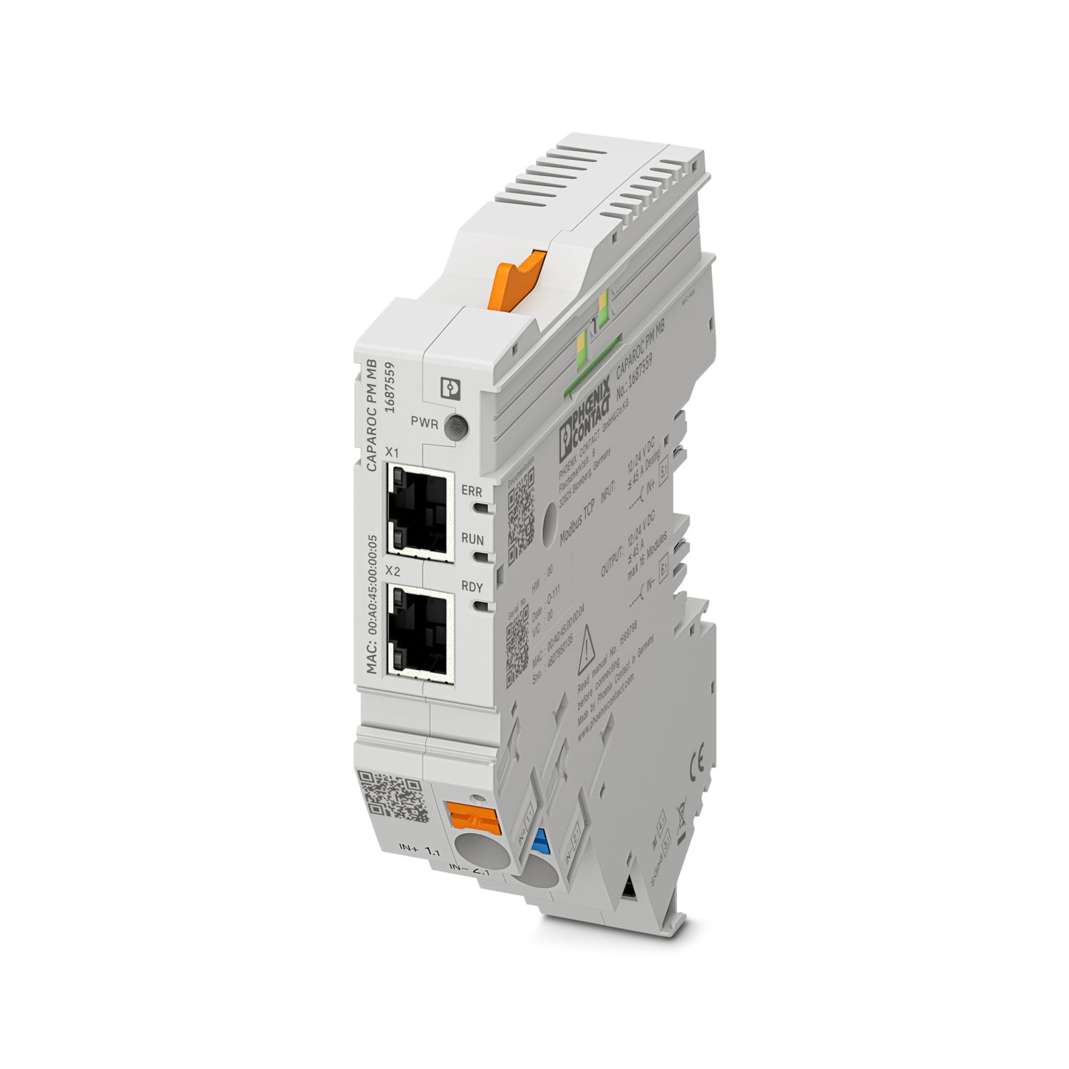
CAPAROC PM MB: 16 circuit breaker modules
CAPAROC PM EC: 16 circuit breaker modules
The channel LED flashes yellow twice every 4 seconds. What does this mean?
This means that the internal communication to the power module is interrupted or faulty.
Check that the modules are mounted correctly and that there is no gap between the modules. If communication is still disrupted, check the side contacts of the...
View more
This means that the internal communication to the power module is interrupted or faulty.
Check that the modules are mounted correctly and that there is no gap between the modules. If communication is still disrupted, check the side contacts of the first module (left) that is flashing, if they are bent, either too far into the module, not centered in the housing opening or otherwise damaged, replace the module.
Can I block the setting of the set currents?
The currents can be locked in different ways:
1. Programming lock: press the PWR button on the power module for > 3 seconds, the PWR LED flashes yellow 3 x, the settings are now locked. Pressing it again for > 3 seconds causes the LED to fla...
View more
The currents can be locked in different ways:
1. Programming lock: press the PWR button on the power module for > 3 seconds, the PWR LED flashes yellow 3 x, the settings are now locked. Pressing it again for > 3 seconds causes the LED to flash green 3 times and unlocks it again.
2. The lock can also be set and released via the communication interface; the operating lock can also be set here, which prevents operation and settings on the device. The lock can then only be released via the interface.