
The fourth generation of the high-performance QUINT POWER power supplies ensures superior system availability by means of new functions. Signaling thresholds and characteristic curves can be individually adjusted via the NFC interface.
The unique SFB technology and preventive function monitoring of the QUINT POWER power supply increase the availability of your application.
QUINT4-PS/1AC/24DC/40
-
Power supply
2904603
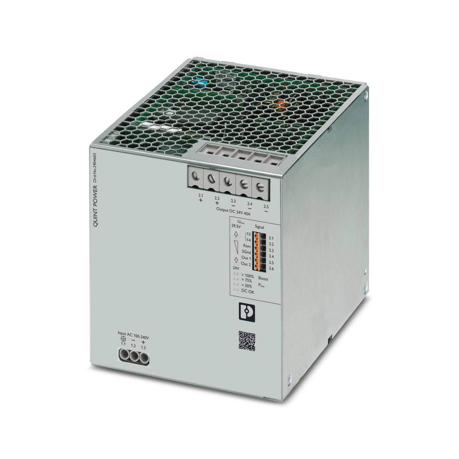
Primary-switched QUINT POWER power supply with free choice of output characteristic curve, SFB (selective fuse breaking) technology, and NFC interface, input: 1-phase, output: 24 V DC/40 A
Free download available.
Downloads
Product details
UL Recognized
Approval ID: FILE E 211944IECEE CB Scheme
Approval ID: SI-7434LR
Approval ID: LR22472797TANK
Approval ID: TA21182MABS
Approval ID: 20-1973616-PDAcULus Listed
Approval ID: FILE E 123528DNV
Approval ID: TAA00000BVBV
Approval ID: 44621/B0 BVcCSAus
Approval ID: 80017552SEMI F47
Approval ID: SEMI F47cUL Listed
Approval ID: FILE E 199827UL Listed
Approval ID: FILE E 199827


Your advantages
Most powerful output side: easy system expansion, reliable heavy load startup and miniature circuit breaker tripping
Most robust input side: high noise immunity, thanks to integrated gas-filled surge arrester (up to 6 kV) and ≥ 20 ms mains failure buffer time
Most comprehensive signaling: preventive function monitoring reports critical operating states before errors occur
Available pre-configured: from a batch quantity of just 1
Frequently asked questions
Can I trigger a standard miniature circuit breaker with the power supply?
Yes, standard miniature circuit breakers can be triggered safely with the QUINT power supply. Please refer to the SFB Technology section in the data sheet.
What power reserves are available?
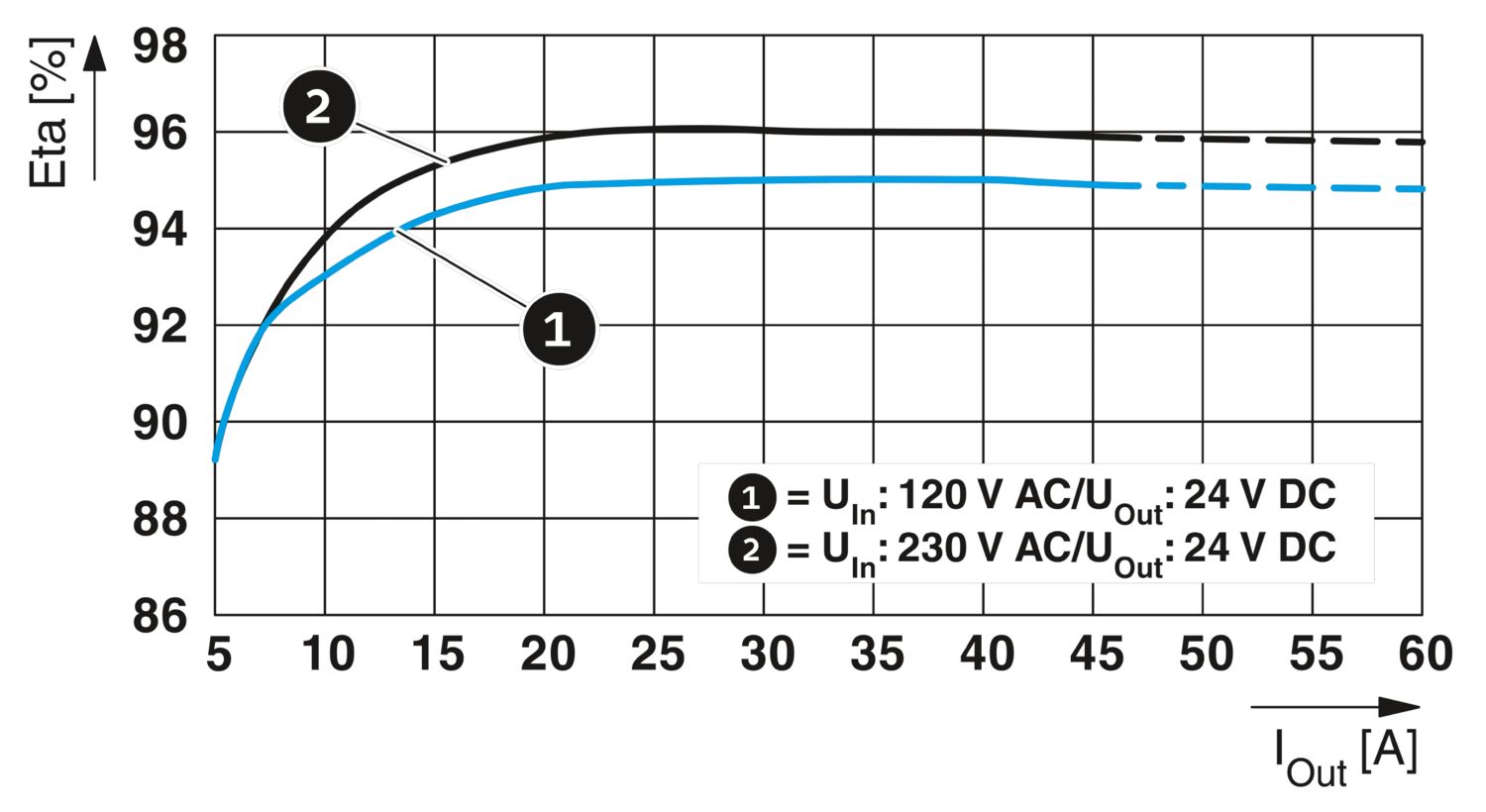
For system expansion purposes, the sustained static boost supports the load supply with 45 A. The static boost is available at an ambient temperature of up to 40°C.
The QUINT POWER power supply provides a dynamic boost of up to 60 A for reliable s...
View more
For system expansion purposes, the sustained static boost supports the load supply with 45 A. The static boost is available at an ambient temperature of up to 40°C.
The QUINT POWER power supply provides a dynamic boost of up to 60 A for reliable starting of heavy loads. This temporary power supply to the load lasts a maximum of 5 s at an ambient temperature of up to 60°C
Can the power supply also be operated with a DC input voltage?
Yes, the QUINT POWER power supply is also approved for the DC input voltage range of 110 V DC ... 250 V DC (-18% ... +40%).
What advantage does the gas discharge tube offer in the power supply?
The integrated gas discharge tube ensures that the QUINT POWER power supply has a very high electrical immunity (up to 6 kV).
Can the input voltage of the power supply be monitored?
Yes, the “Input voltage OK” signal option can be used to signal a failure of the input voltage at an early stage. In the event of a mains failure, the power supply continues to supply the load for at least 29 ms. Failure of the input voltage is signa... View more
Yes, the “Input voltage OK” signal option can be used to signal a failure of the input voltage at an early stage. In the event of a mains failure, the power supply continues to supply the load for at least 29 ms. Failure of the input voltage is signaled 10 ms before the output voltage falls, which means that this information is provided to the higher-level controller at an early stage.
View lessIs there a way to continuously monitor the output parameters of the power supply?
Yes, the analog signal output of the QUINT POWER power supply can be used for continuous monitoring of current, voltage, and power.
Can the temperature of the power supply be monitored?
Yes, with the “Temperature OK” signal option, an elevated temperature can be signaled even before the QUINT POWER power supply is protected by the power derating.
How can the signal contacts be customized?
The signal contacts can be preset directly when ordering the QUINT POWER power supply via the configurator. Alternatively, the power supply can also be configured at a later time via the QUINT POWER software or QUINT POWER app.
How can the output voltage of the power supply be customized?
The QUINT POWER power supply can be ordered directly with a preset output voltage.
Can the buttons for voltage setting also be disabled?
Yes, the buttons on the front can be locked using the QUINT POWER software or QUINT POWER app.