
CBM E8 24DC/0.5-10A NO-R
-
Electronic circuit breaker
2905744
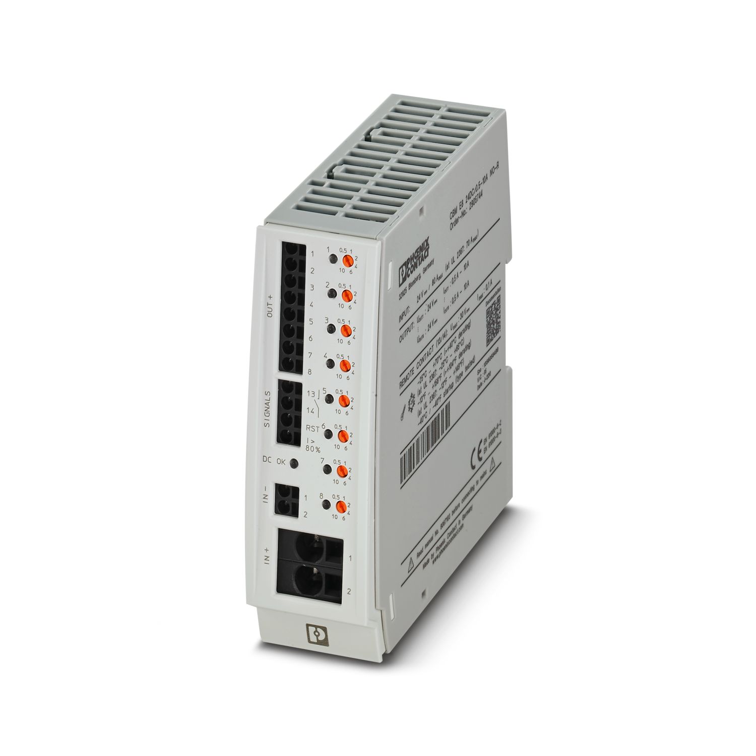
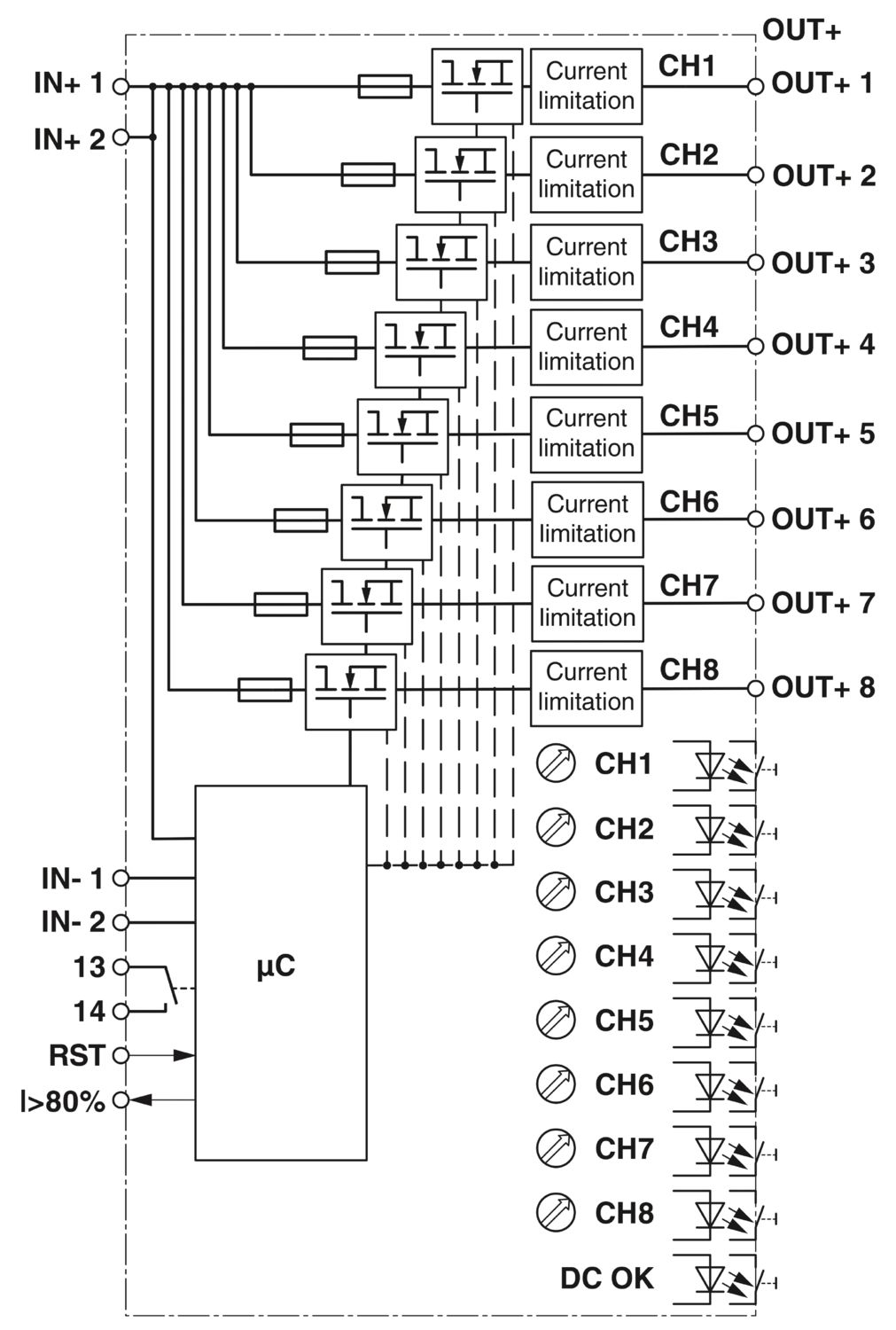
Multi-channel, electronic circuit breaker with active current limitation for protecting eight loads at 24 V DC in the event of overload and short circuit. With nominal current assistant and electronic locking of the set nominal currents. For installation on DIN rails.
Product details
| General | |
| Note | Always connect the negative pole to terminal IN- to ensure the internal power supply. Return currents from the loads must not be fed back to the power supply via IN- of the circuit breaker. |
| Product type | Device circuit breakers |
| Product family | CBM |
| Type | DIN rail module, one-piece |
| Number of positions | 1 |
| No. of channels | 8 |
| Insulation characteristics | |
| Protection class | III |
| Pollution degree | 2 |
| General | |
| Operating voltage | 16.5 V DC ... 30 V DC |
| Rated voltage | 24 V DC |
| Rated current IN | max. 80 A (for double supply IN+ with at least 2 x 6 mm²) |
| Rated current IN | 0.5 / 1 / 2 / 4 / 6 / 10 A DC (adjustable per output channel) |
| Rated current (pre-adjusted) | 0.5 A |
| Rated surge voltage | 0.5 kV |
| Tripping method | E (electronic) |
| Feedback resistance | max. 35 V DC |
| Required backup fuse | Only required if Imax of the power supply > the short-circuit switching capacity. Integrated failsafe element. |
| Short-circuit switching capacity | 300 A |
| Dielectric strength | max. 30 V DC (Load circuit) |
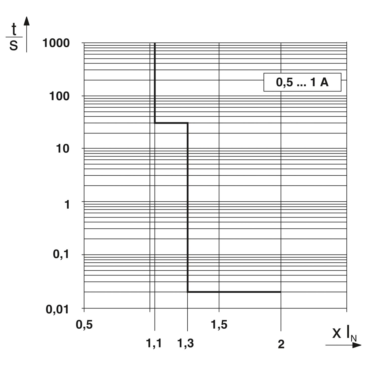
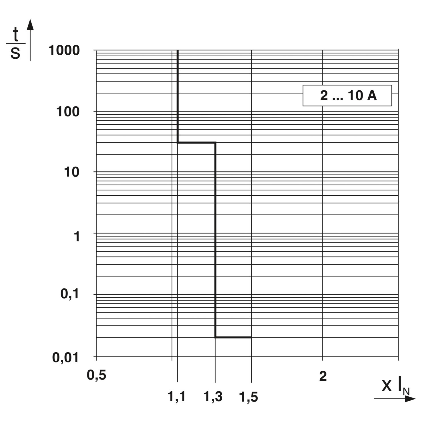
| Active current limitation | typ. 2.0 x IN (0.5 - 1 A) |
| typ. 1.5 x IN (2 - 10 A) | |
| Fuse | electronic |
| Efficiency | > 99 % |
| Closed circuit current I0 | typ. 50 mA |
| Power dissipation | 0.8 W (No-load operation) |
| 13 W (Nominal operation) | |
| Module initialization time | 2 s |
| Waiting time after switch off of a channel | 10 s (at overload / short circuit) |
| Measuring tolerance I | typ. 40 % (0.5 A ... 1 A) |
| typ. 10 % (2 A ... 10 A) | |
| Temperature derating | 40 A DC (at 70 °C) |
| 50 A DC (at 60 °C) | |
| 60 A DC (at 50 °C) | |
| 80 A DC (at 40 °C) | |
| MTBF (IEC 61709, SN 29500) | 1581841 h (at 25 °C with 21 % load) |
| 633955 h (at 40°C with 34.25% load) | |
| 229044 h (at 40°C with 100% load) | |
| Fail-safe element | 15 A DC (per output channel) |
| Contact switching type | without electrical isolation |
| Load circuit | |
| Shutdown time | typ. 0.02 s (0.005 s … 0.05 s at > 1.3 x IN) |
| typ. 30 s (29.5 s … 30.5 s at 1.1 ... 1.3 x IN) | |
| Undervoltage switch-off | ≤ 15.8 V DC (active) |
| ≥ 16.5 V DC (inactive) | |
| Overvoltage switch-off | ≥ 30.5 V DC (active) |
| ≤ 29.5 V DC (inactive) | |
| Max. capacitive load | 75000 µF |
| Switch-on delay | 0.1 s (per output channel) |
| Reset | |
| Input voltage range | 7 V DC ... 30 V DC (Reset with falling edge) |
| Current consumption | typ. 0.4 mA (at 24 V DC) |
| Pulse length | ≥ 50 ms (High signal) |
| ≥ 50 ms (Low signal) | |
| Voltage | < 5 V DC (Low signal) |
| > 8 V DC (High signal) | |
| Status output | |
| Output voltage | 24 V DC |
| Output current | max. 20 mA (when I > 80% at at least one channel) |
| Indicator/remote signaling | |
| Connection name | Remote indication circuit |
| Switching function | N/O contact |
| Operating voltage | 0 V DC ... 30 V DC |
| Operating current | 1 mA DC ... 100 mA DC |
| Main circuit IN+ | |
| Connection method | Push-in connection |
| Stripping length | 18 mm |
| Conductor cross-section rigid | 0.75 mm² ... 16 mm² |
| Conductor cross-section AWG | 20 ... 4 |
| Conductor cross-section, flexible, with ferrule, with plastic sleeve | 0.75 mm² ... 10 mm² |
| Conductor cross-section, flexible, with ferrule, without plastic sleeve | 0.75 mm² ... 16 mm² |
| Main circuit IN- | |
| Connection method | Push-in connection |
| Stripping length | 10 mm |
| Conductor cross-section rigid | 0.2 mm² ... 2.5 mm² |
| Conductor cross-section AWG | 24 ... 12 |
| Conductor cross-section, flexible, with ferrule, with plastic sleeve | 0.25 mm² ... 1.5 mm² |
| Conductor cross-section, flexible, with ferrule, without plastic sleeve | 0.25 mm² ... 2.5 mm² |
| Main circuit OUT | |
| Connection method | Push-in connection |
| Stripping length | 10 mm |
| Conductor cross-section rigid | 0.2 mm² ... 2.5 mm² |
| Conductor cross-section AWG | 24 ... 12 |
| Conductor cross-section, flexible, with ferrule, with plastic sleeve | 0.25 mm² ... 1.5 mm² |
| Conductor cross-section, flexible, with ferrule, without plastic sleeve | 0.25 mm² ... 2.5 mm² |
| Remote indication circuit | |
| Connection method | Push-in connection |
| Stripping length | 10 mm |
| Conductor cross-section rigid | 0.2 mm² ... 2.5 mm² |
| Conductor cross-section AWG | 24 ... 12 |
| Conductor cross-section, flexible, with ferrule, with plastic sleeve | 0.25 mm² ... 1.5 mm² |
| Conductor cross-section, flexible, with ferrule, without plastic sleeve | 0.25 mm² ... 2.5 mm² |
| DC OK LED off | off (No supply voltage) |
| DC OK LED yellow | lit (Undervoltage active, voltage ≤ 15.8 V, active channels switched off and channel LEDs are lit red) |
| flashing (Undervoltage switch-off inactive, device was in undervoltage switch-off) | |
| DC OK LED green | lit (Operating voltage in nominal range 16,5 ... 30 V) |
| DC OK LED red | lit (Overvoltage switch-off active, voltage ≥ 30.5 V, channels switched off and channel LEDs are lit red) |
| flashing (Overvoltage switch-off inactive, device was in overvoltage shutdown) | |
| Channel LED off | off (Channel switched off) |
| Channel LED yellow | lit (Channel switched on, channel load > 80% ) |
| Channel LED yellow-green | flashing (Channel switched on, nominal current assistant active) |
| Channel LED green | lit (Channel switched on) |
| flashing (Channel switched on, programming mode active) | |
| Channel LED red | lit (Channel switched off, over- or undervoltage active) |
| ON temporarily (Channel switched off, 10 s cool-down phase, overload or short-circuit release) | |
| flashing (Channel switched off, ready to be switched back on, overload or short-circuit release) | |
| Channel LED red-yellow | flashing (Channel switched on, overload mode, capacity approximately 110 ... 130% , shutdown after 30 s) |
| Channel LED red-green | flashing (Channel switched off, programming mode active, current adjustment after overload or short-circuit release) |
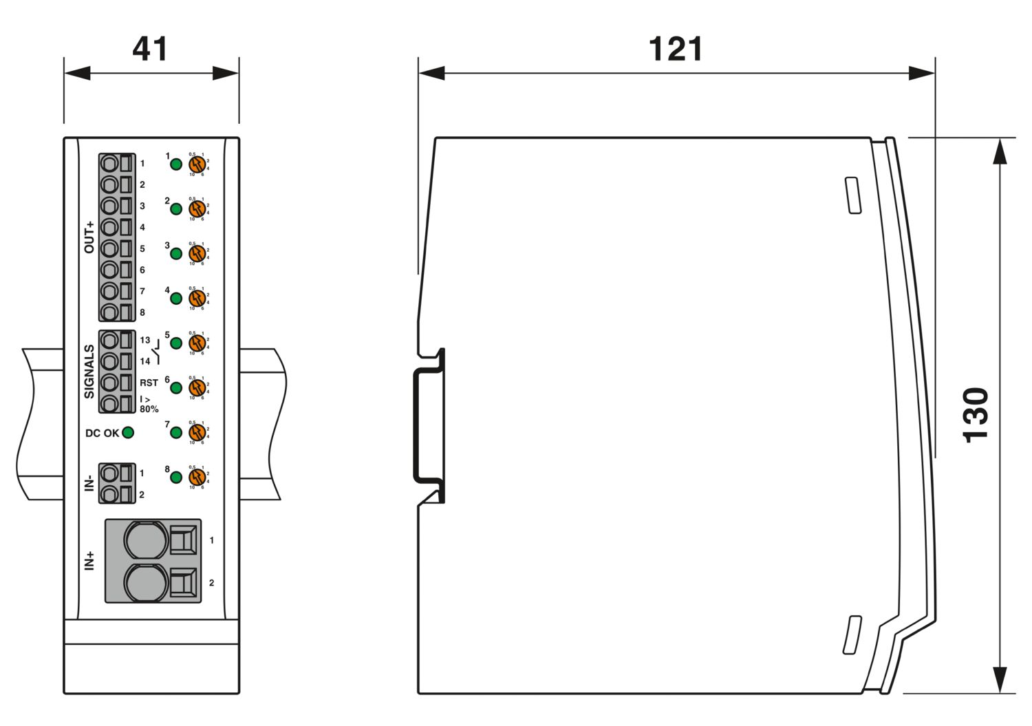
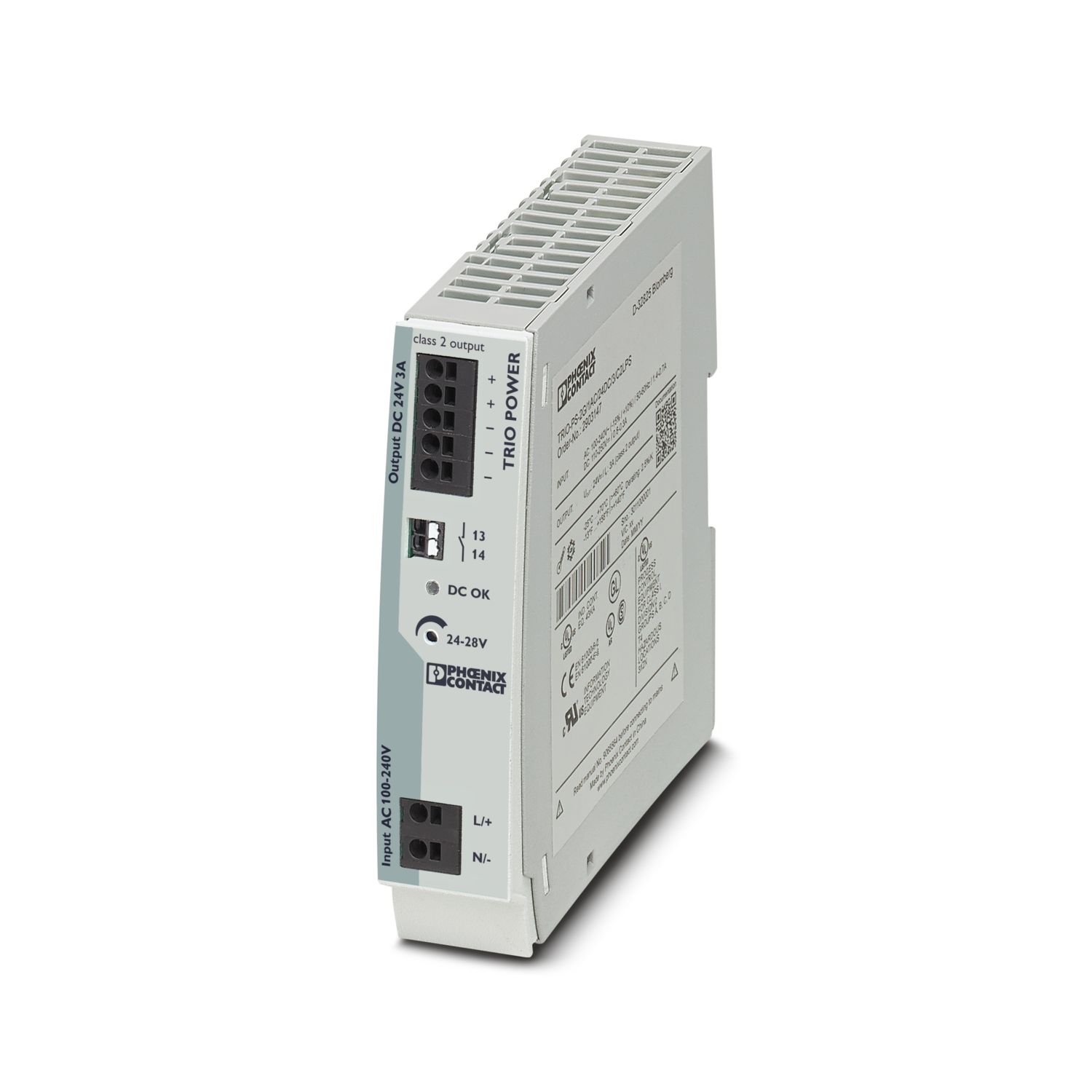
| Dimensional drawing |
|
| Width | 41 mm |
| Height | 130 mm |
| Depth | 121 mm (incl. DIN rail 7.5 mm) |
| Color | light gray (RAL 7035) |
| gray (RAL 7042) | |
| Material | PC |
| PA 6.6 | |
| PC | |
| PBT-FR17 | |
| POM | |
| Flammability rating according to UL 94 | V-0 |
| Ambient conditions | |
| Degree of protection | IP20 |
| Ambient temperature (operation) | -25 °C ... 70 °C (Startup at -40 C type-tested) |
| Ambient temperature (storage/transport) | -40 °C ... 80 °C |
| Altitude | ≤ 6000 m (amsl) |
| Humidity test | 240 h, 95 % RH, 40 °C |
| Shock (operation) | 30g (IEC 60068-2-27, Test Ea) |
| Vibration (operation) | 5 Hz ... 24.9 Hz (Amplitude ±1.6 mm; in accordance with IEC 60068-2-6, Test Fc) |
| 24.9 Hz … 150 Hz (Acceleration 4g; in accordance with IEC 60068-2-6, Test Fc with additional resonance frequency testing in accordance with DNV GL) | |
| UL approval | |
| Identification | UL/C-UL Listed UL 508 |
| UL Recognized UL 2367 | |
| UL ANSI/ISA-12.12.01 Class I, Division 2, Groups A, B, C, D (Hazardous Location) | |
| Shipbuilding approval | |
| Identification | DNV GL |
| Corrosive gas test | |
| Identification | ISA S71.04.2013 G3 Harsh Group A |
| Shipbuilding data | |
| Temperature | D |
| Humidity | B |
| Vibration | B |
| EMC | A |
| Enclosure | Required protection according to the Rules shall be provided upon installation on board |
| Standards/specifications | EN/IEC 61000-6-2 |
| Note | EMC – Immunity for industrial areas |
| Standards/specifications | EN/IEC 61000-6-3 |
| Note | EMC – Emission for residential, business and commercial properties and small operations |
| Standards/specifications | EN/IEC 61000-6-8 |
| Note | EMC interference emission for professional devices that are used in business and commercial areas as well as in small businesses |
| Standards/specifications | IEC 60068-2-6 |
| Note | Environmental influences – Vibrations (sinusoidal) |
| Standards/specifications | IEC 60068-2-1 |
| Note | Environmental influences – Part 2-1: Tests – Test A: Cold |
| Standards/specifications | IEC 60068-2-2 |
| Note | Environmental influences – Part 2-2: Tests – Test B: Dry heat |
| Standards/specifications | IEC 60068-2-78 |
| Note | Environmental influences – Moisture and heat, constant |
| Standards/specifications | IEC 60068-2-30 |
| Note | Environmental influences – Part 2–30: Tests – Test Db: Damp heat, cyclical |
| Mounting type | DIN rail: 35 mm |
Your advantages
Easy to configure, thanks to the nominal current assistant
Active current limitation to improve the capacity of the upstream power supply
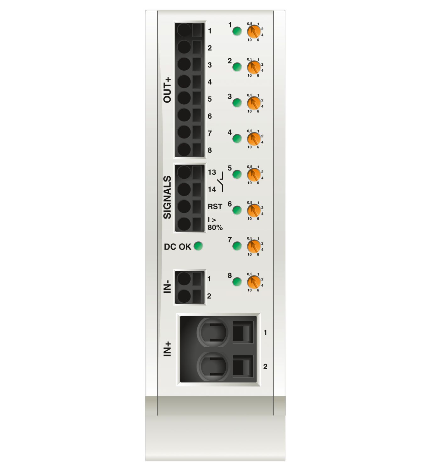
Adjustable in increments per channel:
from 0.5 A to 10 A
Easy system monitoring with early signaling and direct pickup of information at the product
Increased system availability with intelligent detection of under- and overvoltage
Frequently asked questions
Is there a hardware tutorial that explains the functions of the CBM?
How do you set the nominal current for the CBM?
The current can be set in six stages, 0.5; 1; 2; 4; 6 and 10 A. To do this, the current selector switch is turned to the desired value and the LED flashes green to indicate that programming mode is activated. Once the desired current value has been s... View more
The current can be set in six stages, 0.5; 1; 2; 4; 6 and 10 A. To do this, the current selector switch is turned to the desired value and the LED flashes green to indicate that programming mode is activated. Once the desired current value has been selected, it must be confirmed by pressing the LED button for > 1 s to confirm the value.
The ideal nominal current can be easily selected using the nominal current assistant, how does this work?
Turn the nominal current to 10 A and confirm this with the channel button by pressing and holding for > 1 s.
The load should now be started so that the load current flows.
Now the current selector switch can be turned down step by step until the LED flashes green-yellow. Now turn up a level and confirm with the LED button by pressing and holding > 1 s.
How does the CBM behave with a different operating voltage?
The DC OK LED displays the colors green, yellow and red.
Green: CBM is in the operating voltage range 18 V ... 30 V
Yellow: CBM is below the operating voltage, all channels are specifically switched off. If the supply voltage is back in th...
View more
The DC OK LED displays the colors green, yellow and red.
Green: CBM is in the operating voltage range 18 V ... 30 V
Yellow: CBM is below the operating voltage, all channels are specifically switched off. If the supply voltage is back in the nominal range, the channels are switched to the previous state. The DC OK LED then flashes yellow to signal the previous undervoltage.
Red: CBM is above the operating voltage, all channels are specifically switched off and the channel LEDs light up red; if the supply voltage is back within the nominal range, the channels are switched back to the previous state. The DC OK LED then flashes red to indicate the previous overvoltage.
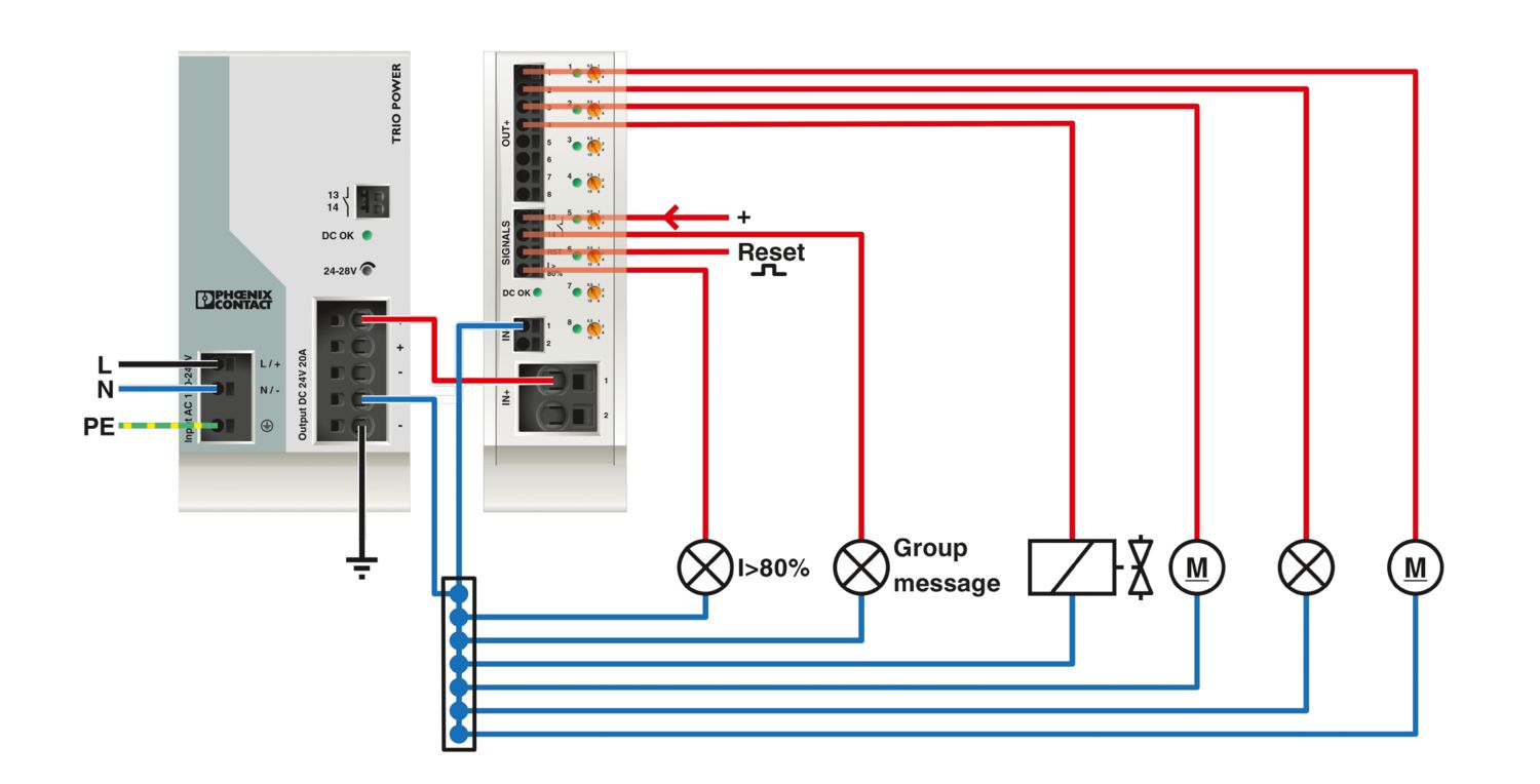
How do I connect the CBM and what are the special features of the feed-in?
The CBM has Push-in connection terminal blocks, simply press the wire with wire end ferrule into the connection terminal block. To release the wire, push a suitable screwdriver into the actuation shaft and remove the wire.
The IN+ and IN- connecti...
View more
The CBM has Push-in connection terminal blocks, simply press the wire with wire end ferrule into the connection terminal block. To release the wire, push a suitable screwdriver into the actuation shaft and remove the wire.
The IN+ and IN- connections are used to supply the CBM, the IN- terminal block is smaller as it is only used to supply the CBM, the load currents must not flow back via the CBM. This minimizes a possible voltage drop across the line. The IN+, on the other hand, must carry the total current of all subsequent load currents.
What signals does the CBM offer?
NO - potential free remote contact 13-14
This indicates the status of the system. If there is at least one fault shutdown, it issues a message.
closed = there is no fault
open = there is at least one fault shutdown
RST - reset input<...
View more
NO - potential free remote contact 13-14
This indicates the status of the system. If there is at least one fault shutdown, it issues a message.
closed = there is no fault
open = there is at least one fault shutdown
RST - reset input
Channels that have been switched off due to an error are switched on again via a falling edge.
I > 80% - Signal output
Potential-bound collective signal, if the current flowing on a channel is greater than 80% of the set nominal current, a HIGH signal (24 V) is output.