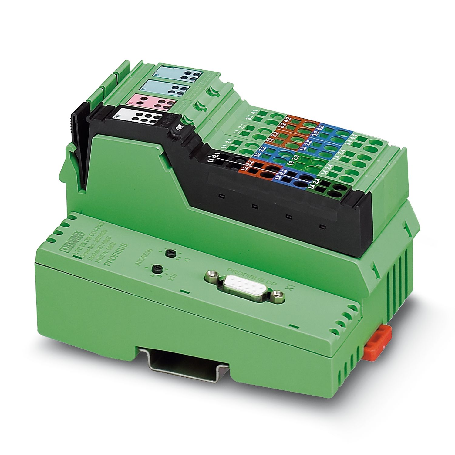
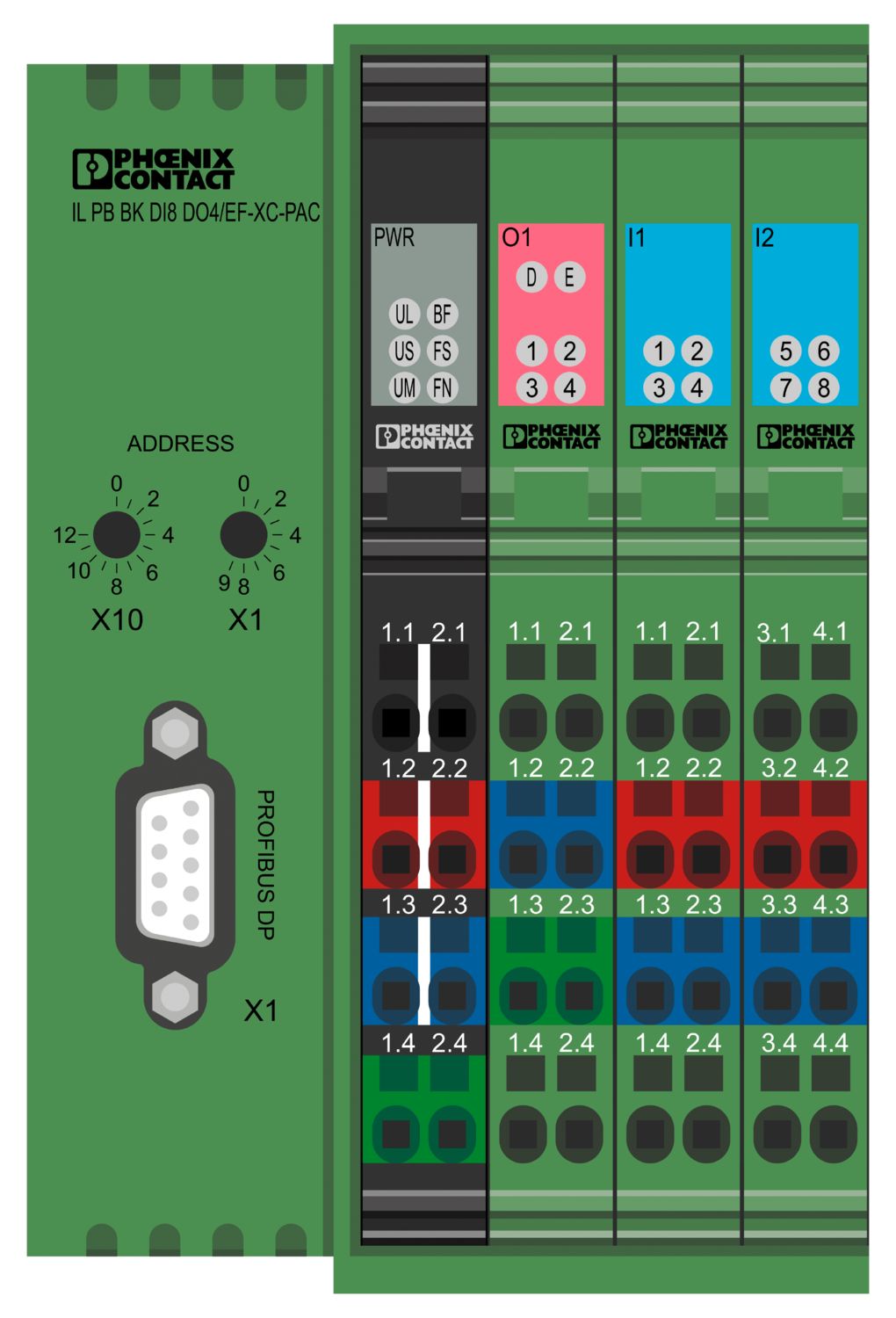
The bus coupler with integrated I/Os is intended for use within a PROFIBUS network and represents the link to the Inline I/O system. Up to 61 Inline devices can be connected to the bus coupler. A corresponding GSD file is available for integrating the Inline station into the programming system. This file can be downloaded via the product at www.phoenixcontact.com/products.
IL PB BK DI8 DO4/EF-XC-PAC
-
Bus coupler
2702132
Inline, Bus coupler, PROFIBUS DP, D-SUB-9 female connector, Digital inputs: 8, 24 V DC, connection technology: 3-conductor, Digital outputs: 4, 24 V DC, 500 mA, connection technology: 3-conductor, Extreme conditions version, transmission speed in the local bus: 500 kbps / 2 Mbps, degree of protection: IP20, including Inline connectors and marking fields
Free download available.
Downloads
Product details
| Dimensional drawing |
|
| Width | 80 mm |
| Height | 119.8 mm |
| Depth | 71.5 mm |
| Note on dimensions | Specfications with connectors |
| Color | green |
| PROFIBUS DP | |
| No. of channels | 1 |
| Connection method | D-SUB-9 female connector |
| Number of positions | 9 |
| Transmission speed | 9.6 kbps ... 12 Mbps |
| Inline local bus | |
| Connection method | Inline data jumper |
| Transmission speed | 500 kbps / 2 Mbps (automatic detection, no combined system) |
| Fieldbus: Local bus gateway | |
| Max. number of local bus devices | 61 (The on-board I/Os are two devices) |
| System limits | |
| Number of supported devices | max. 63 (per station) |
| Number of local bus devices that can be connected | max. 61 (The on-board I/Os are two devices) |
| Number of devices with parameter channel | max. 16 |
| Number of supported branch terminals with remote bus branch | 0 |
| Response time of I/Os | typ. 4 ms (aligned I/Os; transmission speed: PROFIBUS 1.5 Mbps, local bus 500 kbps) |
| Module | |
| ID code (hex) | 0B50 |
| Input address area | 8 bit (or 1 byte, selection in the GSD file) |
| Output address area | 4 bit (or 1 byte, selection in the GSD file) |
| Register length | 16 bit |
| Digital: | |
| Input name | Digital inputs |
| Description of the input | EN 61131-2 type 1 |
| Number of inputs | 8 |
| Connection method | Inline connector |
| Connection technology | 3-conductor |
| Input voltage | 24 V DC |
| Input voltage range "0" signal | -30 V DC ... 5 V DC |
| Input voltage range "1" signal | 15 V DC ... 30 V DC |
| Nominal input voltage UIN | 24 V DC |
| Nominal input current at UIN | typ. 3 mA |
| Typical input current per channel | typ. 3 mA |
| Typical response time | approx. 500 µs |
| Delay at signal change from 0 to 1 | 2.9 ms |
| Delay at signal change from 1 to 0 | 2.9 ms |
| Protective circuit | Reverse polarity protection; Suppressor diode |
| Digital: | |
| Output name | Digital outputs |
| Connection method | Inline connector |
| Connection technology | 3-conductor |
| Number of outputs | 4 |
| Protective circuit | Short-circuit and overload protection; Freewheeling circuit in the output driver |
| Output voltage | 24 V DC -1 V (At nominal current) |
| Maximum output current per module | max. 2 A |
| Nominal output voltage | 24 V DC |
| Output current when switched off | max. 10 µA (When not loaded, a voltage can be measured even at an output that is not set.) |
| Nominal load, inductive | 12 VA (1.2 H, 48 Ω) |
| Nominal load, lamp | 12 W |
| Nominal load, ohmic | 12 W |
| Reverse voltage resistance to short pulses | Reverse voltage proof |
| Behavior with overload | Auto restart |
| Behavior with inductive overload | Output can be destroyed |
| Behavior at voltage switch-off | The output follows the power supply without delay |
| Signal delay | typ. 2.9 ms |
| Overcurrent shut-down | min. 0.7 A |
| Product family | Inline |
| Type | modular |
| Inline | |
| Scope of supply | including Inline connectors and marking fields |
| No. of channels | 12 |
| Special properties | Extreme conditions version |
| Diagnostics messages | Short-circuit or overload of the digital outputs yes |
| Sensor supply failure yes | |
| Failure of the actuator supply yes |
| Power dissipation | typ. 1.7 W (entire device) |
| Potentials: Bus coupler supply UBK; Communications power UL (7.5 V) and the analog supply UANA (24 V) are generated from the bus coupler supply. | |
| Supply voltage | 24 V DC (via Inline connector) |
| Supply voltage range | 19.2 V DC ... 30 V DC (including all tolerances, including ripple) |
| Current draw | max. 0.98 A (with max. number of connected I/O terminal blocks) |
| min. 80 mA (without connected I/O terminal blocks) | |
| Potentials: Communications power (UL) | |
| Supply voltage | 7.5 V DC |
| Potentials: Supply of analog modules (UANA) | |
| Supply voltage | 24 V DC |
| Supply voltage range | 19.2 V DC ... 30 V DC (including all tolerances, including ripple) |
| Potentials: Main circuit supply (UM) | |
| Supply voltage | 24 V DC (via Inline connector) |
| Supply voltage range | 19.2 V DC ... 30 V DC (including all tolerances, including ripple) |
| Current draw | max. 8 A DC |
| min. 3 mA (without connected peripherals) | |
| Potentials: Segment circuit supply (US) | |
| Supply voltage | 24 V DC (via Inline connector) |
| Supply voltage range | 19.2 V DC ... 30 V DC (including all tolerances, including ripple) |
| Current draw | max. 8 A DC |
| min. 6 mA (without connected peripherals) | |
| Connection technology | |
| Connection name | Inline connector |
| Conductor connection | |
| Connection method | Spring-cage connection |
| Conductor cross-section rigid | 0.08 mm² ... 1.5 mm² |
| Conductor cross-section flexible | 0.08 mm² ... 1.5 mm² |
| Conductor cross-section AWG | 28 ... 16 |
| Stripping length | 8 mm |
| Inline connector | |
| Connection method | Spring-cage connection |
| Conductor cross-section, rigid | 0.08 mm² ... 1.5 mm² |
| Conductor cross-section, flexible | 0.08 mm² ... 1.5 mm² |
| Conductor cross-section AWG | 28 ... 16 |
| Stripping length | 8 mm |
| Ambient conditions | |
| Ambient temperature (operation) | -25 °C ... 55 °C |
| -40 °C ... 70 °C (Extended, see section “Tested successfully: use under extreme ambient conditions” in the data sheet.) | |
| Degree of protection | IP20 |
| Air pressure (operation) | 70 kPa ... 106 kPa (up to 3000 m above sea level) |
| Air pressure (storage/transport) | 70 kPa ... 106 kPa (up to 3000 m above sea level) |
| Ambient temperature (storage/transport) | -40 °C ... 85 °C |
| Permissible humidity (operation) | 10 % ... 95 % (non-condensing) |
| Permissible humidity (storage/transport) | 10 % ... 95 % (according to DIN EN 61131-2) |
| Protection class | III (IEC 61140, EN 61140, VDE 0140-1) |
| Mounting type | DIN rail mounting |
| Item number | 2702132 |
| Packing unit | 1 pc |
| Note | Made to order (non-returnable) |
| Sales key | DR01 |
| Product key | DRI112 |
| GTIN | 4046356981774 |
| Weight per piece (including packing) | 339.9 g |
| Weight per piece (excluding packing) | 339.9 g |
| Customs tariff number | 85176200 |
| Country of origin | DE |
UNSPSC
| UNSPSC 21.0 | 32151600 |
| China RoHS | |
| Environment friendly use period (EFUP) |
EFUP-50
An article-related China RoHS declaration table can be found in the download area for the respective article under "Manufacturer declaration". For all articles with EFUP-E, no China RoHS declaration table issued and required.
|
| EU REACH SVHC | |
| REACH candidate substance (CAS No.) | No substance above 0.1 wt% |
Compatible products
-
-
CLIPFIX 35-5 - End bracket 3022276
-
ESL 62X46 - Insert strip 0809502
-
IB IL FIELD 8 - Marking field 2727515
-
ESL 62X10 - Insert strip 0809492
-
IB IL FIELD 2 - Marking field 2727501
-
IL BKDIO-PLSET - Connector set 2878599
-
IB IL SCN-12-ICP - Inline connector 2727611
-
IB IL SCN-12-OCP - Inline connector 2727624
-
SUBCON-PLUS-PROFIB - D-SUB bus connector 2744348
-
SUBCON-PLUS-PROFIB/SC2 - D-SUB bus connector 2708232
-
SUBCON-PLUS-PROFIB/PG/SC2 - D-SUB bus connector 2708245
-
SUBCON-PLUS-PROFIB/90/IDC - D-SUB bus connector 2313672
-
SUBCON-PLUS-PROFIB/90/PG/IDC - D-SUB bus connector 2313685
-
SUBCON-PLUS-PROFIB/90/SC - D-SUB bus connector 2313698
-
SUBCON-PLUS-PROFIB/90/PG/SC - D-SUB bus connector 2313708
-
SUBCON-PLUS-PROFIB/AX/SC - D-SUB bus connector 2744380
-
SUBCON-PLUS-PROFIB/35/M12 - D-SUB bus connector 2902320
-
SUBCON-PLUS-PROFIB/90/M12 - D-SUB bus connector 2902318
Your advantages
PROFIBUS connection via 9-pos. D-SUB socket
8 digital inputs, 4 digital outputs (on-board)
Connection of a maximum of 16 PCP devices
DP/V1 for class 1 and class 2 masters
PROFIBUS data transmission speed of 9.6 kbps to 12 Mbps
I&M functions
Diagnostic and status indicators
IO-Link call
Can be used under extreme ambient conditions
Extended temperature range of -40 °C ... +70 °C (see “Tested successfully: use under extreme ambient conditions” in the data sheet)
Coated PCBs
PHOENIX CONTACT
586 Fulling Mill Road, Middletown, PA 17057