
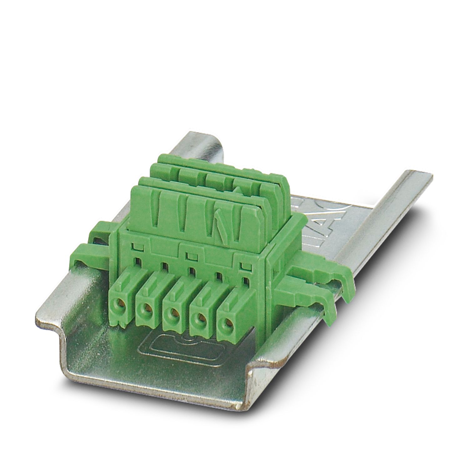
MINI MCR-SL-UI-F-SP
-
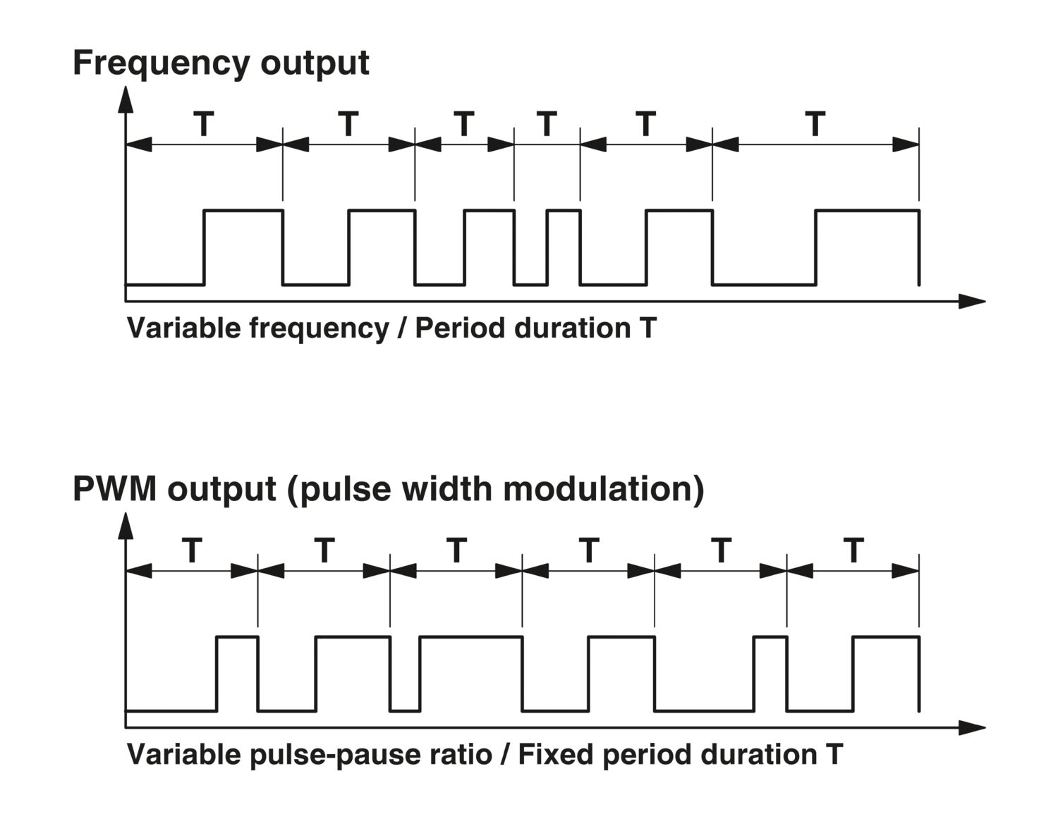
Frequency converter
2810243

MCR analog frequency converter for converting standard analog signals into frequency signals or PWM signals, with spring-cage connection. Replacement part: 2902032 MINI MCR-2-UI-FRO-PT.
Free download available.
Downloads
Product details
| Product type | Frequency value transformer |
| Product family | MINI Analog |
| No. of channels | 1 |
| Insulation characteristics | |
| Overvoltage category | II |
| Pollution degree | 2 |
| Rated insulation voltage | 30 V AC |
| 50 V DC | |
| Electrical isolation | Basic insulation in accordance with EN 61010 |
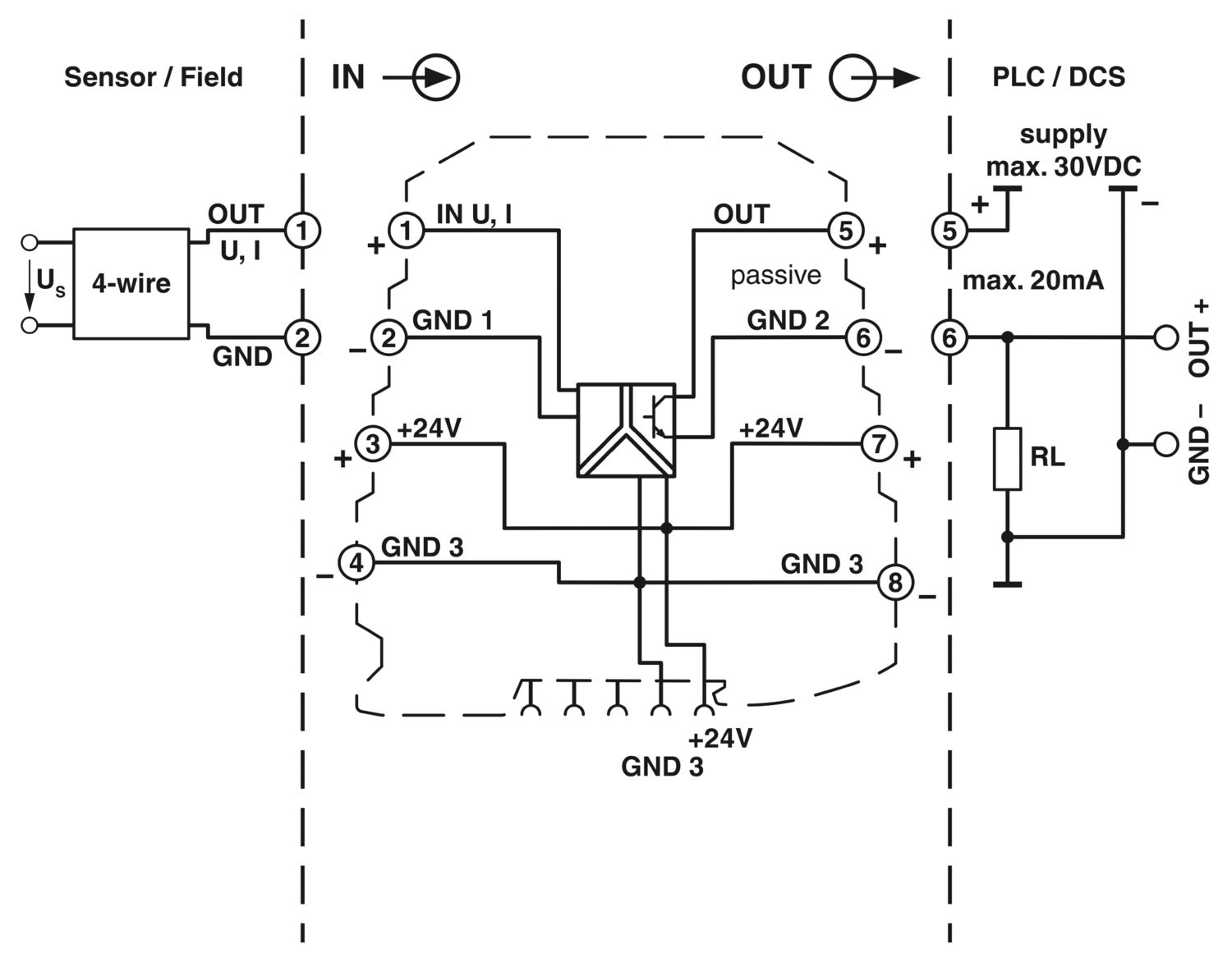
| Electrical isolation between input and output | yes |
| Test voltage, input/output/supply | 1.5 kV AC (50 Hz, 60 s) |
| Step response (0–99%) | < 15 ms (+ (1/f) smallest filter) |
| < 1 s (+ (1/f) largest filter) | |
| Maximum temperature coefficient | < 0.02 %/K |
| Temperature coefficient, typical | < 0.02 %/K |
| Maximum transmission error | ≤ 0.1 % (> 7 kHz ≤ 0.2 %) |
| Supply | |
| Nominal supply voltage | 24 V DC |
| Supply voltage range | 19.2 V DC ... 30 V DC (The DIN rail connector (ME 6,2 TBUS-2 1,5/5-ST-3,81 GN, item no. 2869728) can be used to bridge the supply voltage. It can be snapped onto a 35 mm DIN rail in accordance with EN 60715) |
| Max. current consumption | < 10 mA (at 24 V DC) |
| Power consumption | < 200 mW |
| Signal | |
| Number of inputs | 1 |
| Configurable/programmable | Yes |
| Voltage input signal | 0 V ... 5 V |
| 1 V ... 5 V | |
| 0 V ... 10 V | |
| 2 V ... 10 V | |
| Max. voltage input signal | 30 V DC |
| Current input signal | 0 mA ... 20 mA |
| 4 mA ... 20 mA | |
| 0 mA ... 10 mA | |
| 2 mA ... 10 mA | |
| Max. current input signal | 100 mA |
| Input resistance of voltage input | approx. 110 kΩ |
| Input resistance current input | approx. 50 Ω |
| Behavior in the event of an error | Alarm in the form of a red LED |
| Frequency: | |
| Frequency output | 0 Hz ... 10 kHz |
| 0 Hz ... 5 kHz | |
| 0 Hz ... 2.5 kHz | |
| 0 Hz ... 1 kHz | |
| 0 Hz ... 500 Hz | |
| 0 Hz ... 250 Hz | |
| 0 Hz ... 100 Hz | |
| 0 Hz ... 50 Hz | |
| Load min. | 4 mA ≤ (UL / RL) ≤ 20 mA |
| Output signal PWM | 7.8 kHz (10 bit) |
| 3.9 kHz (10 bit) | |
| 1.9 kHz (12 bit) | |
| 977 Hz (12 bit) | |
| 488 Hz (14 bit) | |
| 244 Hz (14 bit) | |
| 122 Hz (16 bits) | |
| 61 Hz (16 bits) | |
| Load min. | 12 mA ≤ (UL/RL) ≤ 20 mA |
| Load current maximum | 20 mA |
| Maximum switching voltage | 30 V |
| Overrange/underrange | can be set (via DIP switch) |
| Protective circuit | Short-circuit protection, polarity reversal protection |
| Signal | |
| Number of outputs | 1 |
| Connection method | Spring-cage connection |
| Stripping length | 8 mm |
| Conductor cross-section rigid | 0.2 mm² ... 2.5 mm² |
| Conductor cross-section flexible | 0.2 mm² ... 2.5 mm² |
| Conductor cross-section AWG | 24 ... 12 |
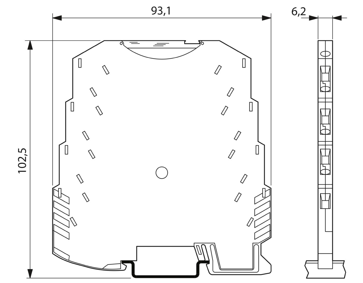
| Dimensional drawing |
|
| Width | 6.2 mm |
| Height | 93.1 mm |
| Depth | 102.5 mm |
| Color | green (RAL 6021) |
| Housing material | PBT |
| Fire protection for rail vehicles (DIN EN 45545-2) R22 | HL 1 - HL 2 |
| Fire protection for rail vehicles (DIN EN 45545-2) R23 | HL 1 - HL 2 |
| Fire protection for rail vehicles (DIN EN 45545-2) R24 | HL 1 - HL 2 |
| Ambient conditions | |
| Degree of protection | IP20 |
| Ambient temperature (operation) | -20 °C ... 65 °C |
| Ambient temperature (storage/transport) | -40 °C ... 85 °C |
| Altitude | ≤ 2000 m |
| Permissible humidity (operation) | 5 % ... 95 % (non-condensing) |
| CE | |
| Certificate | CE-compliant |
| ATEX | |
| Identification | II 3 G Ex nA IIC T4 Gc X |
| UL, USA/Canada | |
| Identification | UL 508 Recognized |
| Class I, Div. 2, Groups A, B, C, D T4 | |
| Shipbuilding approval | |
| Identification | BBBAA |
| Certificate | DNV GL TAA00000N1 |
| Electromagnetic compatibility | Conformance with EMC directive |
| Noise immunity | EN 61000-6-2 |
| Note | When being exposed to interference, there may be minimal deviations. |
| Noise emission | |
| Standards/regulations | EN 61000-6-4 |
| Electrostatic discharge | |
| Standards/regulations | EN 61000-4-2 |
| Electrostatic discharge | |
| Comments | Safety measures must be taken to prevent electrostatic discharge. |
| Electromagnetic HF field | |
| Designation | Electromagnetic RF field |
| Standards/regulations | EN 61000-4-3 |
| Typical deviation from the measuring range final value | 2 % |
| Fast transients (burst) | |
| Designation | Fast transients (burst) |
| Standards/regulations | EN 61000-4-4 |
| Typical deviation from the measuring range final value | 2 % |
| Surge current load (surge) | |
| Standards/regulations | EN 61000-4-5 |
| Surge current load (surge) | |
| Comments | Criterion B |
| Conducted interference | |
| Designation | Conducted interferences |
| Standards/regulations | EN 61000-4-6 |
| Typical deviation from the measuring range final value | 2 % |
| Electrical isolation | Basic insulation in accordance with EN 61010 |
| Mounting type | DIN rail mounting |
| Mounting position | any |
Your advantages
Power supply possible via the foot element (TBUS)
Error indication via diagnostic LED and analog signal
Highly-compact analog-to-frequency transducer for electrical isolation, amplification, conversion, and filtering of standard signals to create frequencies or PWM signals
Configurable interference filter
3-way isolation
PWM output of 5 ... 95 %
Input and output signals can be configured via DIP switches