
QUINT DC/DC converter with maximum functionality
DC/DC converters alter the voltage level, regenerate the voltage at the end of long cables or enable the creation of independent supply systems by means of electrical isolation.
QUINT DC/DC converters magnetically and therefore quickly trip circuit breakers with six times the nominal current, for selective and therefore cost-effective system protection. The high level of system availability is additionally ensured, thanks to preventive function monitoring, as it reports critical operating states before errors occur.
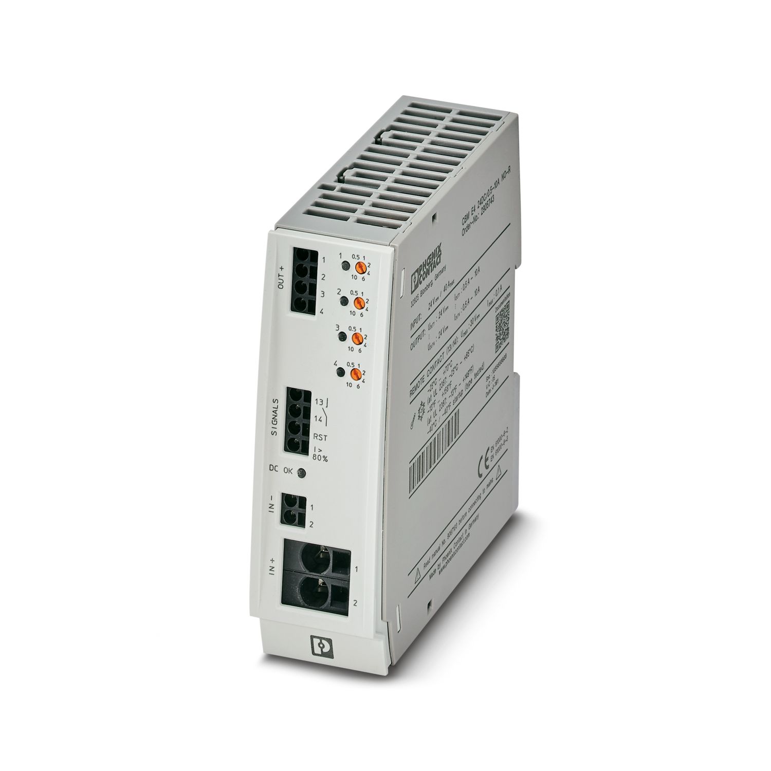
QUINT4-PS/24DC/24DC/20/PT
-
DC/DC converter
2910121
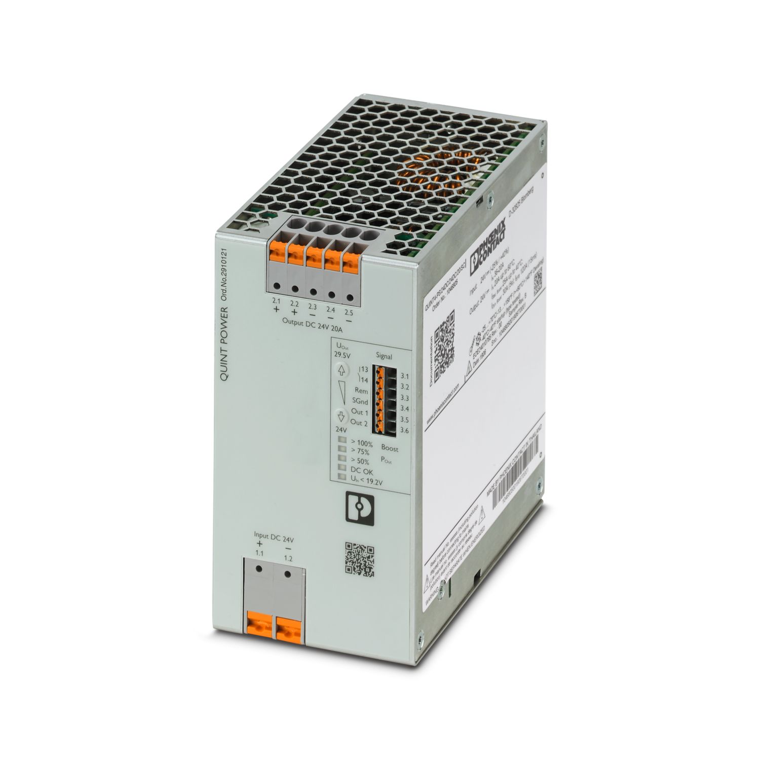

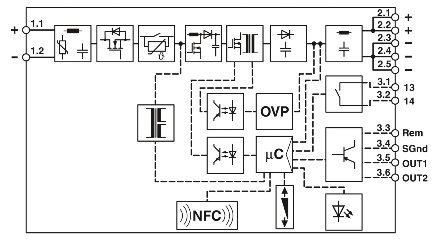

Primary-switched DC/DC converter, QUINT POWER DIN rail mounting, SFB Technology (Selective Fuse Breaking), input: 24 V DC, output: 24 V DC / 20 A
Free download available.
Downloads
Product details
LR
Approval ID: LR22472797TANK
Approval ID: TA21182MABS
Approval ID: 26-0442641-PDAcULus Listed
Approval ID: FILE E 123528Type approved
Approval ID: SI-SIQ BG 005/076BV
Approval ID: 57060/B0 BVDNV
Approval ID: TAA00001YDcCSAus
Approval ID: 80031630cULus Listed
Approval ID: FILE E 199827
Your advantages
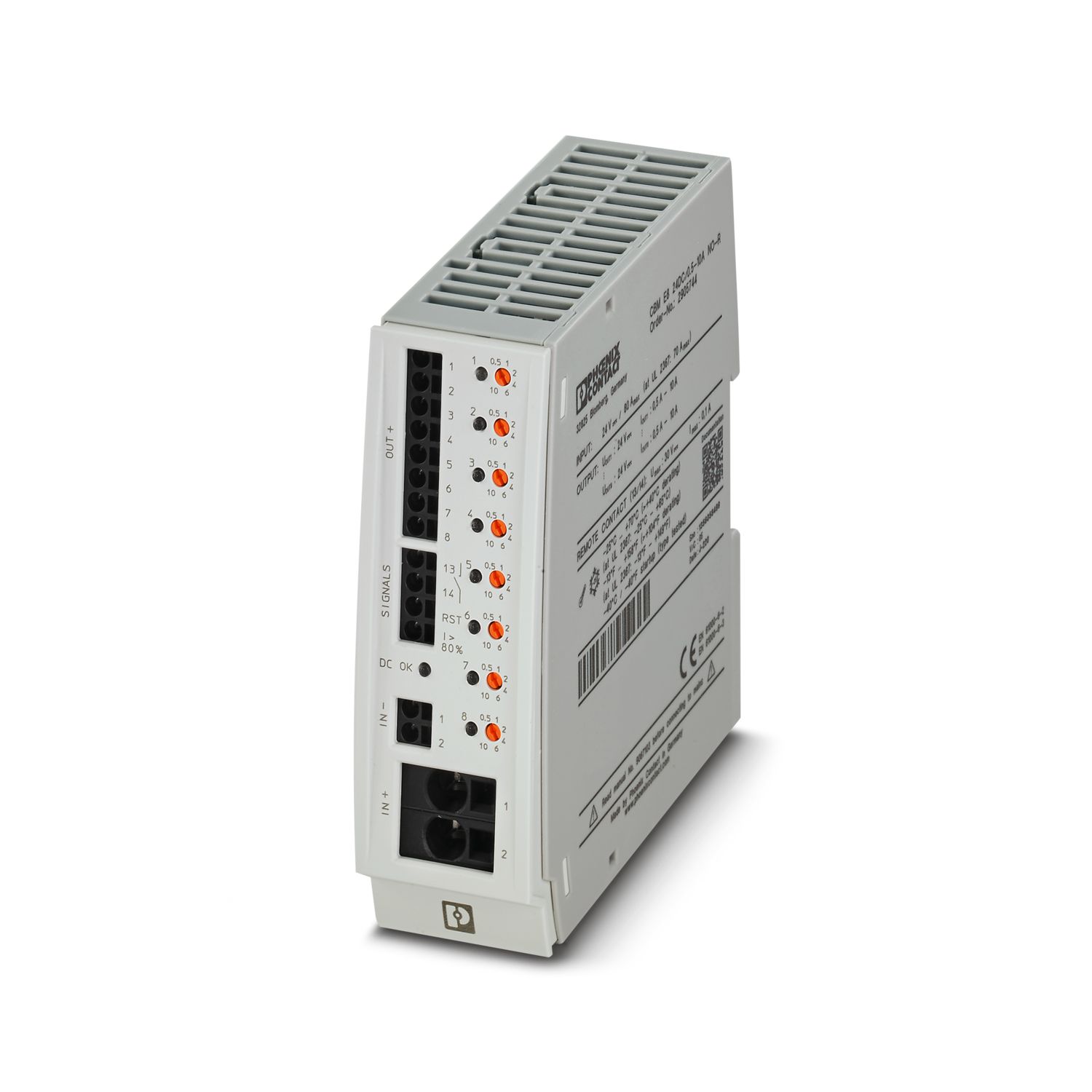
Most powerful output side: easy system expansion, reliable heavy load startup and miniature circuit breaker tripping
Most comprehensive signaling: preventive function monitoring reports critical operating states before errors occur
Free selection between Push-in and screw connection
Frequently asked questions
For which applications can a DC/DC converter be used?
DC/DC converters change or stabilize the voltage level and provide a regulated supply for your application even in the event of voltage fluctuations. They compensate for the voltage drop over long cable lengths, and the electrical isolation prevents ... View more
DC/DC converters change or stabilize the voltage level and provide a regulated supply for your application even in the event of voltage fluctuations. They compensate for the voltage drop over long cable lengths, and the electrical isolation prevents interference with sensitive loads and system components.
View lessCan I use the QUINT4 DC/DC converter to selectively trigger a standard miniature circuit breaker in my application?
Yes, with the QUINT4 DC/DC converters > 100 W, standard miniature circuit breakers can be safely triggered by SFB Technology. Please refer to the "SFB Technology" section in the data sheet, which can be found under "Downloads".
Why is such a high rated current specified on the data sheet for the external backup fuse?
The backup fuses specified on the data sheet are guaranteed not to trip unintentionally even under the most unfavorable operating conditions (e.g., maximum output power at minimum input voltage).
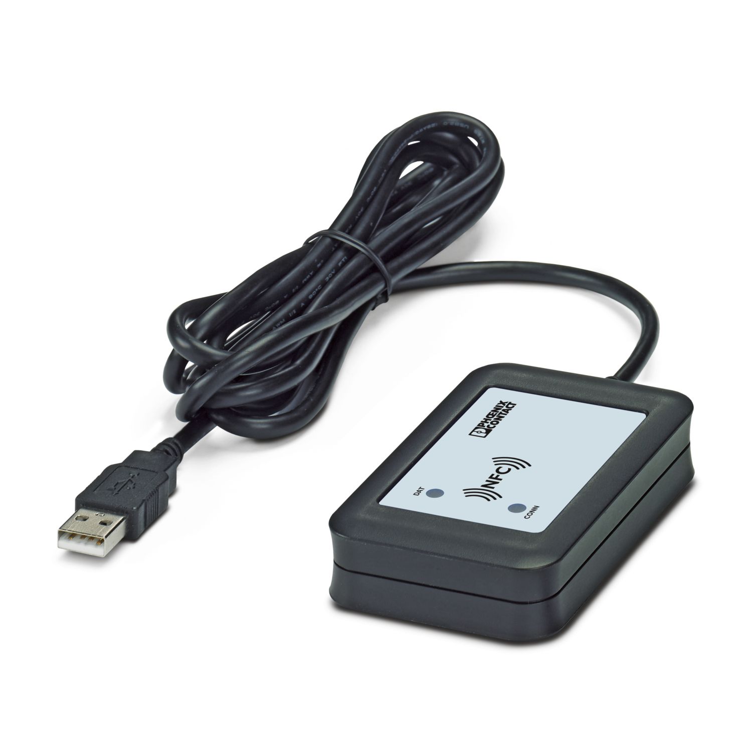
How can I configure the device?
You can carry out the configuration either with your mobile device using the QUINT POWER app, or with your Windows PC using the QUINT POWER software, which you can find under "Downloads" and "Software". Please note that the USB programming adapter 2909681 is required for the PC.