
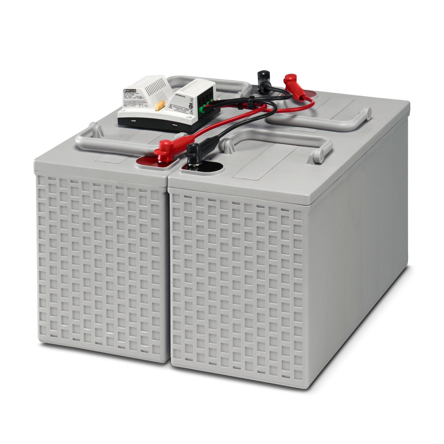
The TRIO DC UPS combines an uninterruptible power supply with an integrated power supply, thereby saving space in the control cabinet. The robust solution offers comprehensive functions such as signaling, diagnostics, connection to IPCs and PLCs, and a cold restart function in a compact housing. Tool-free wiring with Push-in Technology makes handling and startup particularly easy. With the dynamic boost and intelligent battery charging behavior, the TRIO DC UPS ensures a particularly high degree of reliability. Select the appropriate TRIO battery module for your required buffer time and effortlessly create your individual complete system.
TRIO3-UPS/1AC/24DC/10
-
Uninterruptible power supply
1359610
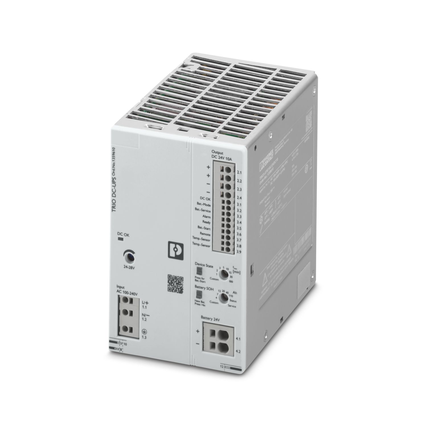


TRIO UPS - UPS with integrated power supply, DIN rail mounting, Push-in connection, output: 24 V DC / 10 A
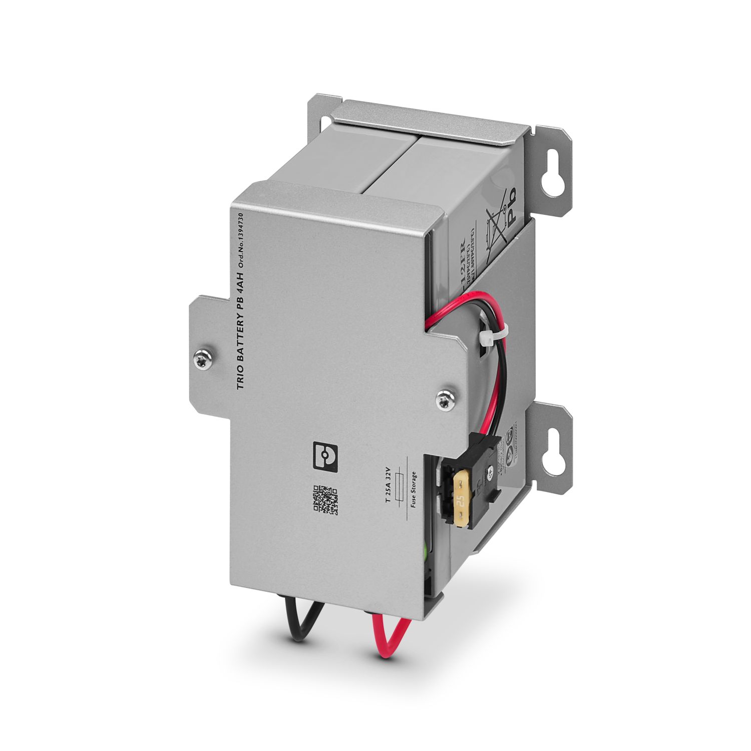
This product needs further products for operation.
Mandatory accessories
Product details
| Input voltage range | 100 V AC ... 240 V AC -15 % ... +10 % |
| 115 V AC ... 240 V AC ±10 % (UL) | |
| Voltage type of supply voltage | AC |
| Inrush current integral (I2t) | typ. < 1 A2s |
| Inrush current limitation | typ. < 21 A |
| Frequency range (fN) | 50 Hz ... 60 Hz ±10 % |
| Mains buffering time | typ. 45 ms (120 V AC) |
| Static Boost (IStat.Boost) | 10 A |
| Switch-on time during battery operation (Bat.-Start) | ≤ 5 ms |
| Discharge current to PE | < 3.5 mA |
| Current consumption | typ. 4.23 A (100 V AC) |
| Current consumption IN (UN, IOUT = IN, Icharge = 0) | 2.3 A (120 V AC) |
| Current consumption Imax (UN, IOUT = IStat.Boost, ICharge = max) | 3.7 A (120 V AC) |
| Current consumption INo-Load(UN, IOUT = 0, Icharge = 0) | 0.11 A (120 V AC) |
| Current consumption Icharge (UN, IOUT = 0, Icharge = max) | 1.4 A (120 V AC) |
| Power consumption PN (UN, IOUT = IN, Icharge = 0) | 259 W (120 V AC) |
| Power consumption Pmax (UN, IOUT = IStat.Boost, Icharge = max) | 421 W (120 V AC) |
| Power consumption PNo-Load (UN, IOUT = 0, Icharge = 0) | 7.6 W (120 V AC) |
| Power consumption Pcharge (UN, IOUT = 0, Icharge = max) | 166 W (120 V AC) |
| Input fuse | 10 A (internal (device protection)) |
| Recommended breaker for input protection | 6 A ... 16 A |
| Efficiency | typ. 93.17 % (120 V AC) |
| typ. 93.5 % (230 V AC) | |
| Short-circuit-proof | yes |
| No-load proof | yes |
| Crest factor | typ. 1.72 (120 V AC) |
| typ. 2.04 (230 V AC) | |
| Switch-over time | < 3 ms |
| Output current limit | 10 A |
| UPS connection in parallel | yes, with diode module uncoupled |
| UPS connection in series | no |
| Energy storage device connection in parallel | yes, max. 3 |
| Energy storage device connection in series | no |
| Feedback voltage resistance | ≤ 35 V DC |
| Protection against overvoltage at the output (OVP) | ≤ 35 V DC |
| Residual ripple | < 25 mV |
| Rise time | ≤ 1 s (UOut = 10 % ... 90 %) |
| Mains operation | |
| Output voltage | 24 V DC |
| Output voltage range | 24 V DC ... 28 V DC (>24 V, performance-limited) |
| max. 240 W | |
| Output current IN | 10 A |
| Dynamic BOOST (IDyn.Boost) | 15 A (5 s) |
| Output power (PN) | 240 W |
| Output power (PDyn. Boost) | 360 W (5 s) |
| Maximum no-load power dissipation | ≤ 10 W (120 V AC) |
| ≤ 10 W (230 V AC) | |
| Power loss nominal load max. | ≤ 20 W (120 V AC) |
| ≤ 20 W (230 V AC) | |
| Battery operation | |
| Output voltage | UBAT -0,2 V DC |
| Output voltage range | 19.2 V DC ... 32 V DC |
| Output current IN | 10 A |
| Dynamic BOOST IDyn.Boost (IDyn.Boost) | 15 A (5 s) |
| Output power PN | 240 W |
| Output power PDyn. Boost | 360 W (5 s) |
| Output power POUT (UN, IOUT = Idyn.Boost) | 360 W (5 s) |
| Maximum no-load power dissipation | ≤ 1.5 W (120 V AC) |
| ≤ 1.5 W (230 V AC) | |
| Power loss nominal load max. | ≤ 4 W (120 V AC) |
| ≤ 4 W (230 V AC) | |
| Nominal voltage UN | 24 V DC |
| Charging voltage | max. 32 V DC |
| Charging current (Preset) | 2 A |
| Charging current (Configurable) | 0.2 A ... 5 A (-25 °C ... 55 °C 5K) |
| Charging current (Reduced) | 5 A ... 3.75 A (55°C ... 65°C 5K) |
| Charging current (max.) | 5 A |
| Nominal capacity range | 4 Ah ... 110 Ah |
| Battery technology | VRLA-AGM |
| Charge characteristic curve | IU0U |
| Input | |
| Position | 1.x |
| Connection technology | |
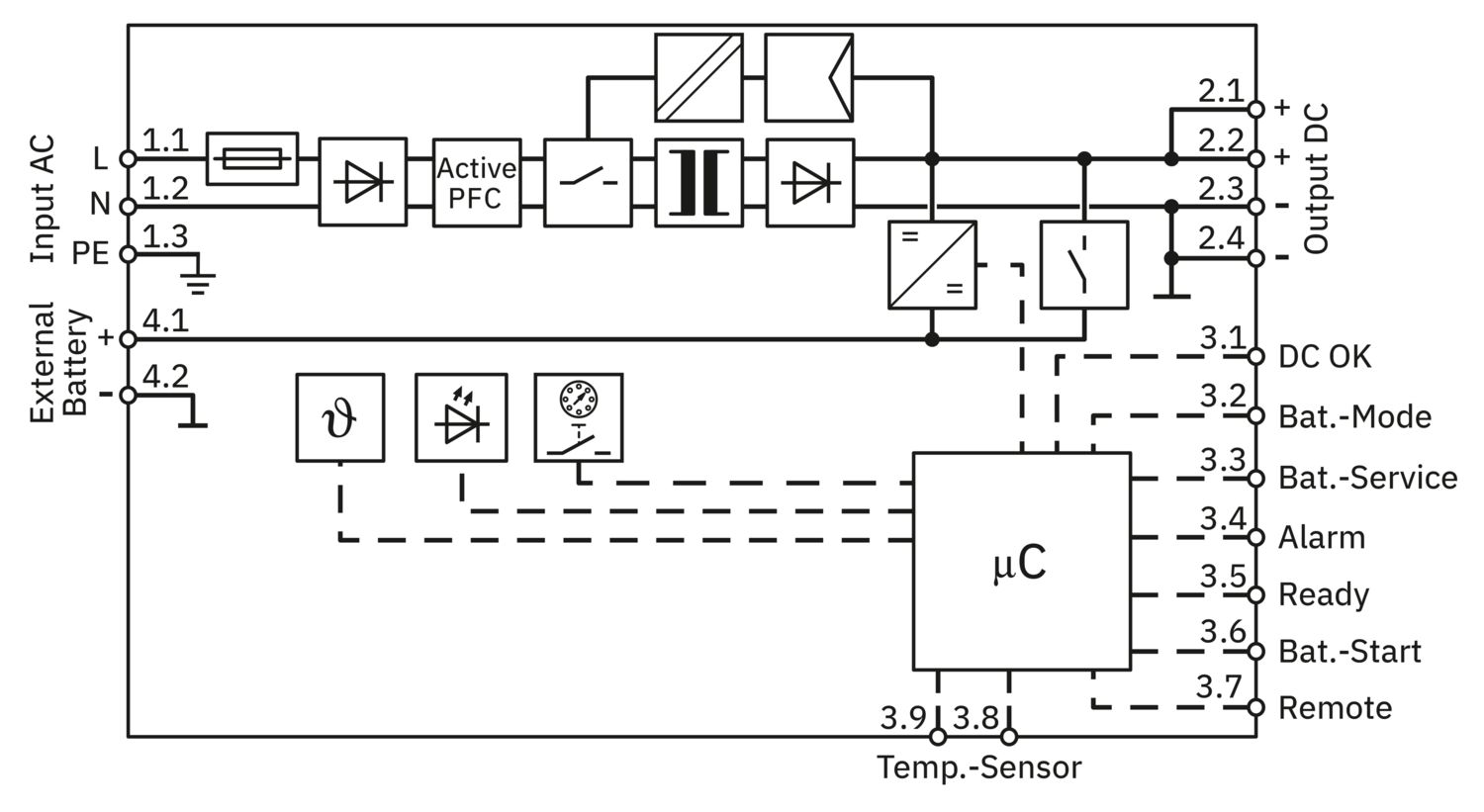
| Position marking | 1.1 (L/+), 1.2 (N/-), 1.3 () |
| Conductor connection | |
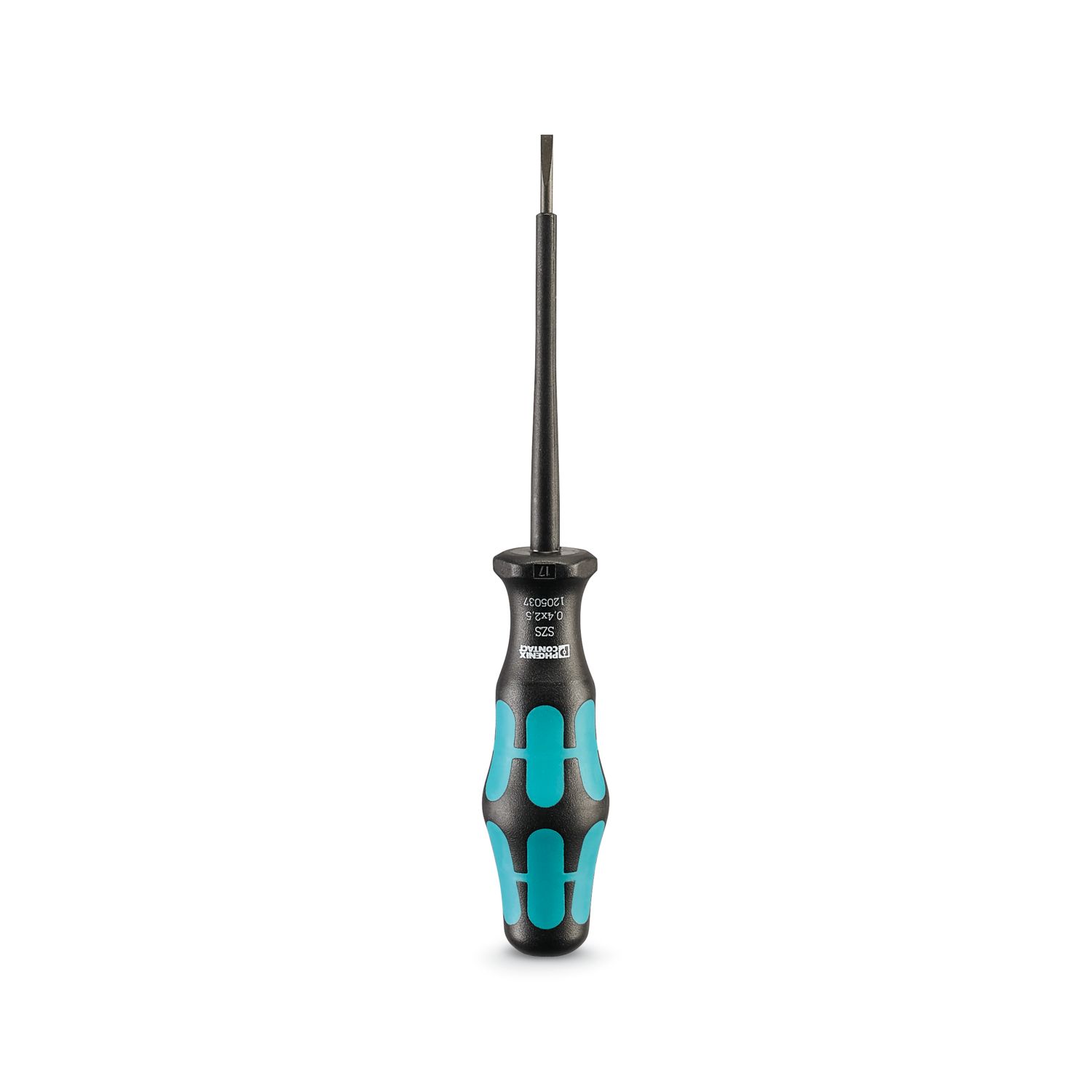
| Connection method | Push-in connection |
| rigid | 0.2 mm² ... 4 mm² |
| 1.5 mm² | |
| flexible | 0.2 mm² ... 2.5 mm² |
| 1.5 mm² | |
| flexible with ferrule without plastic sleeve | 0.25 mm² ... 2.5 mm² |
| 1.5 mm² | |
| flexible with ferrule with plastic sleeve | 0.25 mm² ... 2.5 mm² |
| 1.5 mm² | |
| AWG | 24 ... 12 |
| 16 | |
| Stripping length | 10 mm |
| Output | |
| Position | 2.x |
| Connection technology | |
| Position marking | 2.1 (+), 2.2 (+), 2.3 (-), 2.4 (-) |
| Conductor connection | |
| Connection method | Push-in connection |
| rigid | 0.2 mm² ... 4 mm² |
| 1.5 mm² | |
| flexible | 0.2 mm² ... 2.5 mm² |
| 1.5 mm² | |
| flexible with ferrule without plastic sleeve | 0.25 mm² ... 2.5 mm² |
| 1.5 mm² | |
| flexible with ferrule with plastic sleeve | 0.25 mm² ... 2.5 mm² |
| 1.5 mm² | |
| AWG | 24 ... 12 |
| 16 | |
| Stripping length | 10 mm |
| Battery | |
| Position | 4.x |
| Connection technology | |
| Position marking | 4.1 (+), 4.2 (-) |
| Conductor connection | |
| Connection method | Push-in connection |
| rigid | 0.2 mm² ... 10 mm² |
| 2.5 mm² | |
| flexible | 0.2 mm² ... 6 mm² |
| 2.5 mm² | |
| flexible with ferrule without plastic sleeve | 0.25 mm² ... 6 mm² |
| 2.5 mm² | |
| flexible with ferrule with plastic sleeve | 0.25 mm² ... 4 mm² |
| 2.5 mm² | |
| AWG | 24 ... 8 |
| 14 | |
| Stripping length | 12 mm |
| Signal | |
| Position | 3.x |
| Conductor connection | |
| Connection method | Push-in connection |
| rigid | 0.2 mm² ... 1.5 mm² |
| 0.5 mm² | |
| flexible | 0.2 mm² ... 1.5 mm² |
| 0.5 mm² | |
| flexible with ferrule without plastic sleeve | 0.2 mm² ... 1.5 mm² |
| 0.5 mm² | |
| flexible with ferrule with plastic sleeve | 0.2 mm² ... 0.75 mm² |
| 0.5 mm² | |
| AWG | 24 ... 16 |
| 20 | |
| Stripping length | 8 mm |
| LED signaling | |
| Types of signaling | LED: DC output |
| Function | Visualization of the operating state of the DC output voltage (DC OK) |
| Color | red, yellow, green (multicolor LED) |
| LED off | Device off (Off) |
| LED on (green), DC OK | Output power in operation < 90% (On (green), DC OK) |
| LED on (yellow), IOut > 90 % | Output power in operation > 90% (On (yellow), IOut > 90% ) |
| LED on (red), ISHORT | Output power overload > 150% (On (red), ISHORT) |
| LED on (flashing red) OVP | UOUT > OVP (Over voltage protection) (on (flashing red 50%)) |
| LED signaling | |
| Types of signaling | LED: device state |
| Function | Visual display of the operating state of the UPS |
| Color | red, yellow, green (multicolor LED) |
| LED off | Device off (Off) |
| LED on (green) | Device on (on (green)) |
| LED on (flashing green 90%) | Remote contact is short-circuited with Output (-). (on (flashing green 90%)) |
| LED on (flashing green 10 %) | Signaling time after shutdown in battery operation (on (flashing green 10%)) |
| LED on (yellow) | Battery operation (on (yellow)) |
| LED on (flashing yellow) | Battery charging (on (flashing yellow 50%)) |
| LED on (red) | Group alarm, device (on (red)) |
| LED on (flashing red) | Service mode for battery (on (flashing red 50%)) |
| LED signaling | |
| Types of signaling | LED: battery condition |
| Function | Visual display of the operating state of the battery |
| Color | red, yellow, green (multicolor LED) |
| LED off | Device off (Off) |
| LED on (green) | Battery SOH > 6 months (on (green)) |
| LED on (yellow) | Battery SOH < 6 months (on (yellow)) |
| LED on (red) | Group alarm, battery (on (red)) |
| LED on (flashing red) | Battery SOH = 0 months (on (flashing red 50%)) |
| Signal input Bat.-Start | |
| Signalization designation | Bat.-Start |
| Position | 3.x |
| Position marking | 3.6 (Bat.-Start) |
| Low signal | Connection to Output (-) with < 2.7 kΩ |
| High signal | Open (> 200 kΩ between Bat.-Start and Output (-)) |
| Signal input Remote | |
| Signalization designation | Remote |
| Position | 3.x |
| Position marking | 3.7 (Remote) |
| Low signal | Connection to Output (-) with < 2.7 kΩ |
| High signal | Open (> 200 kΩ between Remote and Output (-)) |
| Signal input Temp.-Sensor | |
| Signalization designation | Temp.-Sensor |
| Position | 3.x |
| Position marking | 3.8 (Temp.-Sensor), 3.9 (Temp.-Sensor) |
| Voltage | max. 3.5 V (when the sensor is not connected) |
| Short-circuit current rating | max. 3 mA |
| Signal output DC OK | |
| Position | 3.x |
| Signalization designation | DC OK |
| Position marking | 3.1 (DC OK) |
| State condition (Contact closed (battery operation)) | UOut > 20.4 V; UOut < 32 V |
| State condition (Contact open (battery operation)) | UOut < 20.4 V; UOut > 32 V |
| Switching output | Transistor output, active |
| Output voltage | 24 V DC |
| Continuous load current | 20 mA |
| LED status indicator | green (LED: DC output) |
| Signal output Battery Mode | |
| Position | 3.x |
| Signalization designation | Bat.-Mode |
| Position marking | 3.2 (Bat.-Mode) |
| State condition (Contact closed) | Device in battery mode |
| State condition (Contact open) | Device in mains mode or device off |
| Switching output | Transistor output, active |
| Output voltage | 24 V DC |
| Continuous load current | 20 mA |
| LED status indicator | yellow (LED: device state) |
| Signal output | |
| Position | 3.x |
| Signalization designation | Bat.-Service |
| Position marking | 3.3 (Bat.-Service) |
| State condition (Contact closed) | Device in battery mode |
| State condition (Contact open) | Device in mains mode or device off |
| Switching output | Transistor output, active |
| Output voltage | 24 V DC |
| Continuous load current | 20 mA |
| LED status indicator | red, flashing (LED: device status) |
| Signal output Alarm | |
| Position | 3.x |
| Signalization designation | Alarm |
| Position marking | 3.4 (Alarm) |
| State condition (Contact closed) | no alarm |
| State condition (Contact open) | Alarm |
| Switching output | Transistor output, active |
| Output voltage | 24 V DC |
| Continuous load current | 20 mA |
| LED status indicator | red (LED: battery status) |
| Signal output Ready | |
| Position | 3.x |
| Signalization designation | Ready |
| Position marking | 3.5 (Ready) |
| State condition (Contact closed (mains operation)) | Battery is fully charged |
| State condition (Contact closed (battery operation)) | As long as output voltage > cut-off voltage |
| State condition (Contact open (mains operation)) | Battery charging |
| State condition (Contact open (battery operation)) | Output voltage < cut-off voltage or device is switched off |
| Switching output | Transistor output, active |
| Output voltage | 24 V DC |
| Continuous load current | 20 mA |
| Product family | TRIO UPS |
| MTBF (IEC 61709, SN 29500) | 1097743 h (25 °C) |
| 667151 h (40 °C) | |
| 310917 h (60 °C) | |
| Insulation characteristics | |
| Protection class | I |
| Degree of pollution | 2 |
| Item dimensions | |
| Width | 88 mm |
| Height | 135 mm |
| Depth | 132 mm |
| Depth (Device depth (DIN rail mounting)) | 125 mm (Device depth (DIN rail mounting)) |
| Installation dimensions | |
| Installation distance right/left | 0 mm / 0 mm |
| Installation distance top/bottom | 50 mm / 50 mm |
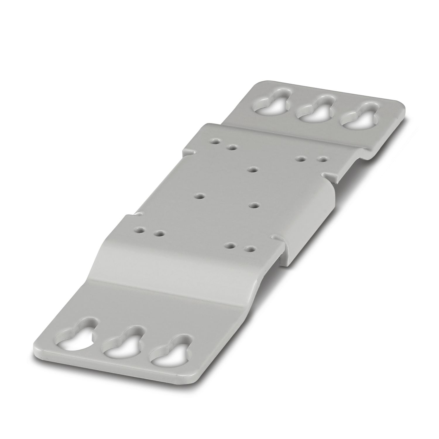
| Mounting type | DIN rail mounting |
| Mounting position | horizontal DIN rail NS 35, EN 60715 |
| Material (Housing front) | PS |
| Flammability rating according to UL 94 (housing / terminal blocks) | V0 |
| Housing material | Aluminum |
| Ambient conditions | |
| Degree of protection | IP20 |
| Ambient temperature (operation) | -25 °C ... 70 °C |
| Ambient temperature (operation) (Output power derating) | > 60 °C (2.5 %/K) |
| Ambient temperature (storage/transport) | -40 °C ... 85 °C |
| Maximum altitude | ≤ 5000 m |
| Maximum altitude (Output power derating) | > 2000 m (10 %/1000 m) |
| Climatic class | 3K3 (EN 60721) |
| Shock | 18 ms, 30g, per spatial direction |
| Vibration (operation) | 5 Hz ... 100 Hz, amplitude ±2.5 mm, 2.3g |
| 30 Hz ... 100 Hz, 2.3g, 90 min. | |
| Overvoltage category | |
| EN 61010-1 | III (≤ 2000 m) / II (≤ 5000 m) |
| EN 61010-2-201 | III (≤ 2000 m) / II (≤ 5000 m) |
| Safety of power supply units up to 1100 V (insulation distances) | |
| Standard designation | Safety of power supply units up to 1100 V (insulation distances) |
| Standards/specifications | DIN EN 61558-2-16 |
| Electrical safety | |
| Standard designation | Electrical safety |
| Standards/specifications | IEC 61010-2-201 (SELV) |
| Electronic equipment for use in power installations | |
| Standard designation | Equipping high voltage installations with electronic equipment |
| Standards/specifications | EN 50178/VDE 0160 (PELV) |
| Safety for measurement, control, and laboratory equipment | |
| Standard designation | Safety for equipment for measurement, control, and laboratory use |
| Standards/specifications | IEC 61010-1 |
| Protective extra-low voltage | |
| Standard designation | Protective extra-low voltage |
| Standards/specifications | IEC 61010-1 (SELV) |
| IEC 61010-2-201 (PELV) | |
| Safe isolation | |
| Standard designation | Safe isolation |
| Standards/specifications | IEC 61010-2-201 |
| Limitation of harmonic line currents | |
| Standard designation | Limitation of harmonic line currents |
| Standards/specifications | EN 61000-3-2 |
| Mains variation/undervoltage | |
| Standard designation | Mains variation/undervoltage |
| Standards/specifications | SEMI F47 |
| EN 61000-4-11 | |
| UL | |
| Identification | UL/C-UL Listed UL 61010-1 |
| UL | |
| Identification | UL/C-UL Listed UL 61010-2-201 |
| ANSI/UL 121201 | |
| Identification | UL/C-UL Listed ANSI/ISA-12.12.01 Class I, Division 2, Groups A, B, C |
| Shipbuilding | |
| Identification | DNV |
| Shipbuilding | |
| Identification | LR |
| Shipbuilding | |
| Identification | Nippon Kaiji Kyokai |
| Electromagnetic compatibility | Conformance with EMC Directive 2014/30/EU |
| Low Voltage Directive | Conformance with Low Voltage Directive 2014/35/EC |
| Interference emission | Interference emission in accordance with EN 61000-6-3 (residential areas), EN 61000-6-4 (industrial areas) and EN 61000-6-8 (commercial areas) |
| Noise immunity | Immunity in accordance with EN 61000-6-2 (industrial) |
| Conducted noise emission | |
| Standards/regulations | EN 61000-6-3 |
| Noise emission | |
| Standards/regulations | EN 61000-6-3 |
| Harmonic currents | |
| Standards/regulations | EN 61000-3-2 |
| Flicker | |
| Standards/regulations | EN 61000-3-3 |
| Electrostatic discharge | |
| Standards/regulations | EN 61000-4-2 |
| Electrostatic discharge | |
| Contact discharge | 6 kV (Test Level 3) |
| Discharge in air | 8 kV (Test Level 3) |
| Electromagnetic HF field | |
| Standards/regulations | EN 61000-4-3 |
| Electromagnetic HF field | |
| Frequency range | 80 MHz ... 6 GHz |
| Test field strength | 10 V/m |
| Frequency range | 1.4 GHz ... 6 GHz |
| Test field strength | 3 V/m |
| Fast transients (burst) | |
| Standards/regulations | EN 61000-4-4 |
| Fast transients (burst) | |
| Input | ± 4 kV (100 kHz) |
| Output | ± 2 kV (100 kHz) |
| Signal | ± 2 kV (100 kHz) |
| Voltage (Battery) | ± 2 kV (100 kHz) |
| Surge voltage load (surge) | |
| Standards/regulations | EN 61000-4-5 |
| Surge voltage load (surge) | |
| Input | 2 kV (Test Level 4 - symmetrical) |
| 4 kV (Test Level 4 - asymmetrical) | |
| Output | 1 kV (Test Level 3 - symmetrical) |
| 2 kV (Test Level 3 - asymmetrical) | |
| Signal | 1 kV (Test Level 2 - asymmetrical) |
| Conducted interference | |
| Standards/regulations | EN 61000-4-6 |
| Conducted interference | |
| Frequency range | 0.15 MHz ... 80 MHz |
| Voltage | 10 V |
| Item number | 1359610 |
| Packing unit | 1 pc |
| Minimum order quantity | 1 pc |
| Product key | CMUD13 |
| GTIN | 4063151688073 |
| Weight per piece (including packing) | 1,343 g |
| Weight per piece (excluding packing) | 1,150 g |
| Country of origin | CN |
ECLASS
| ECLASS-13.0 | 27040705 |
| ECLASS-15.0 | 27040705 |
ETIM
| ETIM 9.0 | EC000382 |
UNSPSC
| UNSPSC 21.0 | 39121000 |
| EU RoHS | |
| Fulfills EU RoHS substance requirements | Yes |
| Exemption | 34, 6(c), 7(a), 7(c)-I |
| China RoHS | |
| Environment friendly use period (EFUP) |
EFUP-25
An article-related China RoHS declaration table can be found in the download area for the respective article under "Manufacturer declaration". For all articles with EFUP-E, no China RoHS declaration table issued and required.
|
| EU REACH SVHC | |
| REACH candidate substance (CAS No.) | Hexahydromethylphthalic anhydride (CAS: n/a) |
| Lead (CAS: 7439-92-1) | |
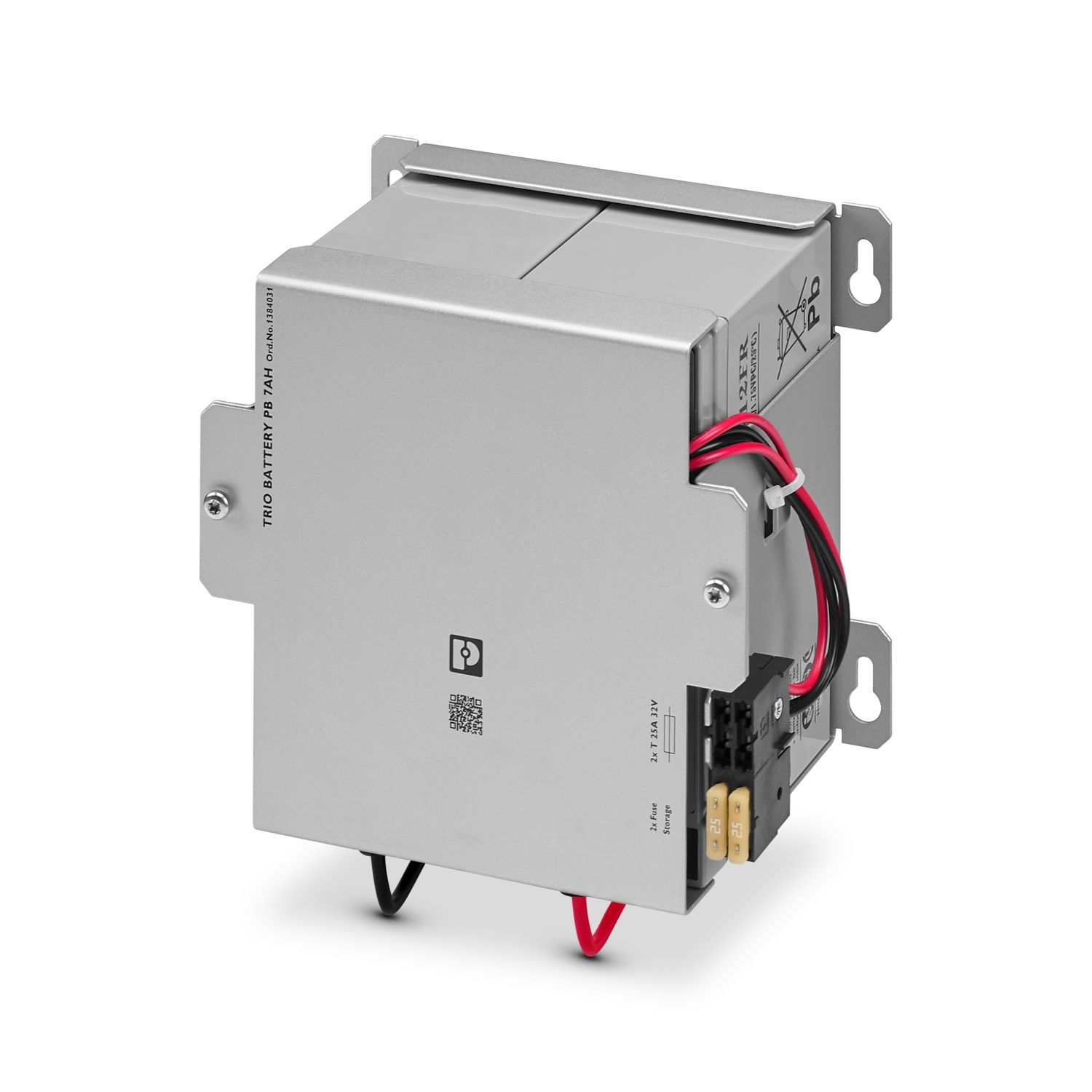
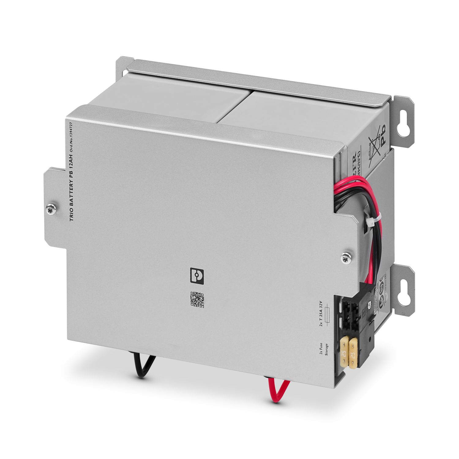
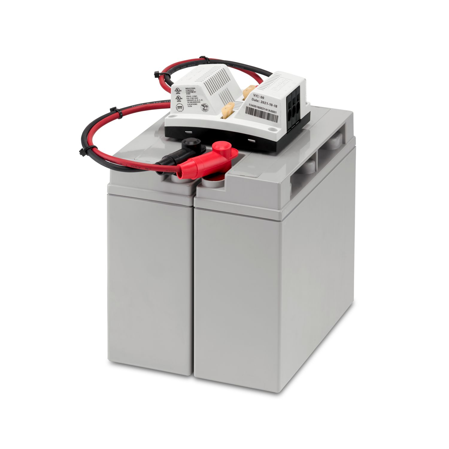
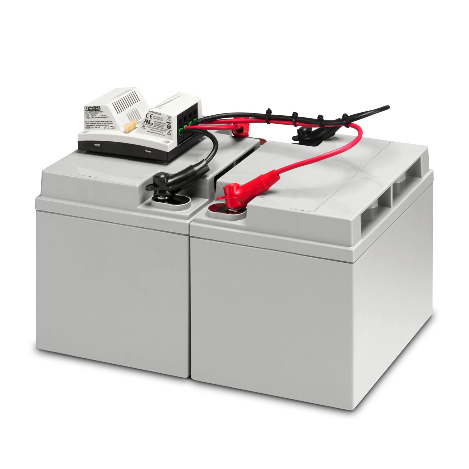
Compatible products
Your advantages
Space-saving with the combination of a UPS and power supply in a compact housing
Easy handling ensured by tool-free wiring with Push-in connection technology
Robust and reliable due to dynamic boost and intelligent battery charging behavior
Direct diagnostics with multicolor LEDs and signal contacts for a clear status display