PSR-MC42-2NO-1DO-24DC-SC
-
Safety relays
2702901
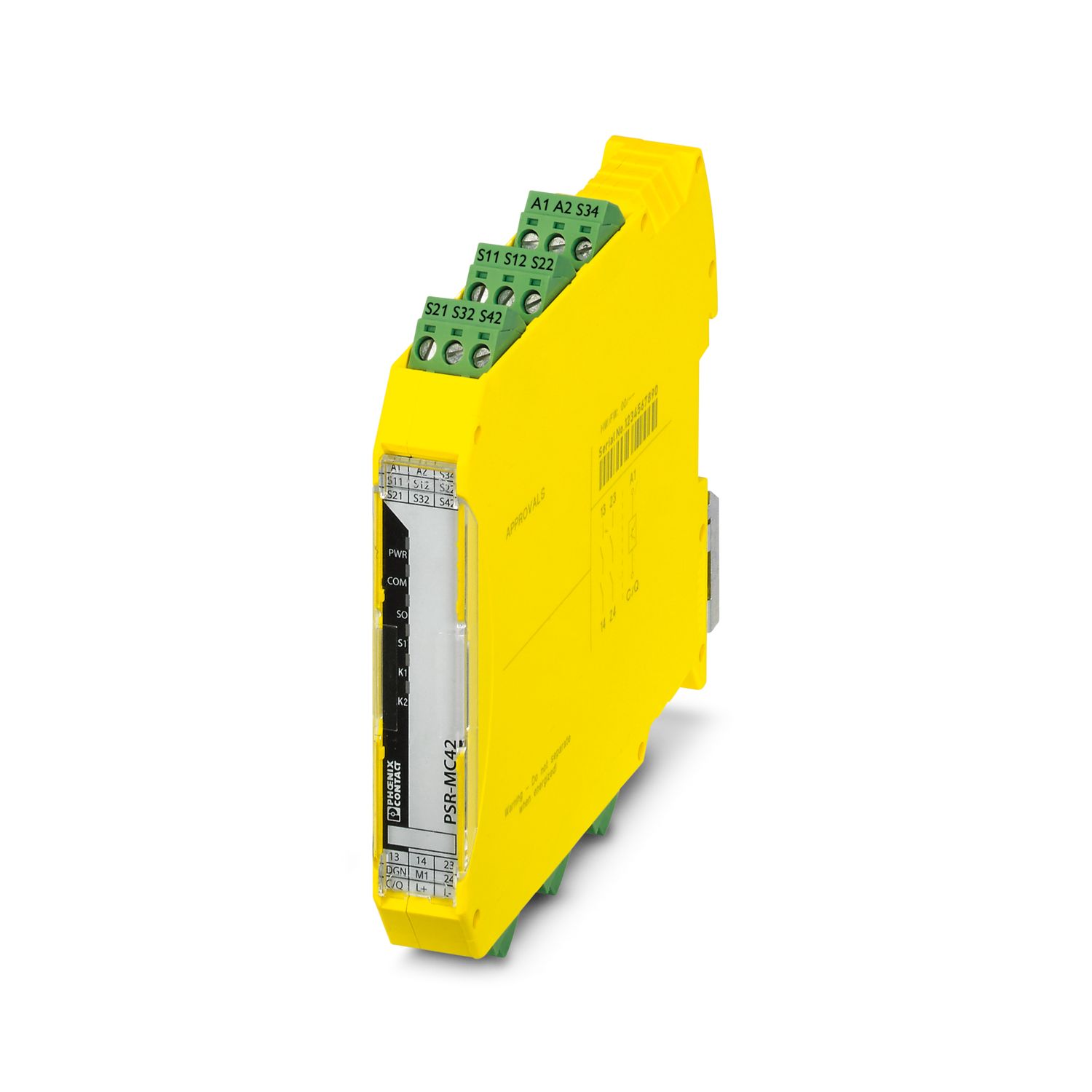
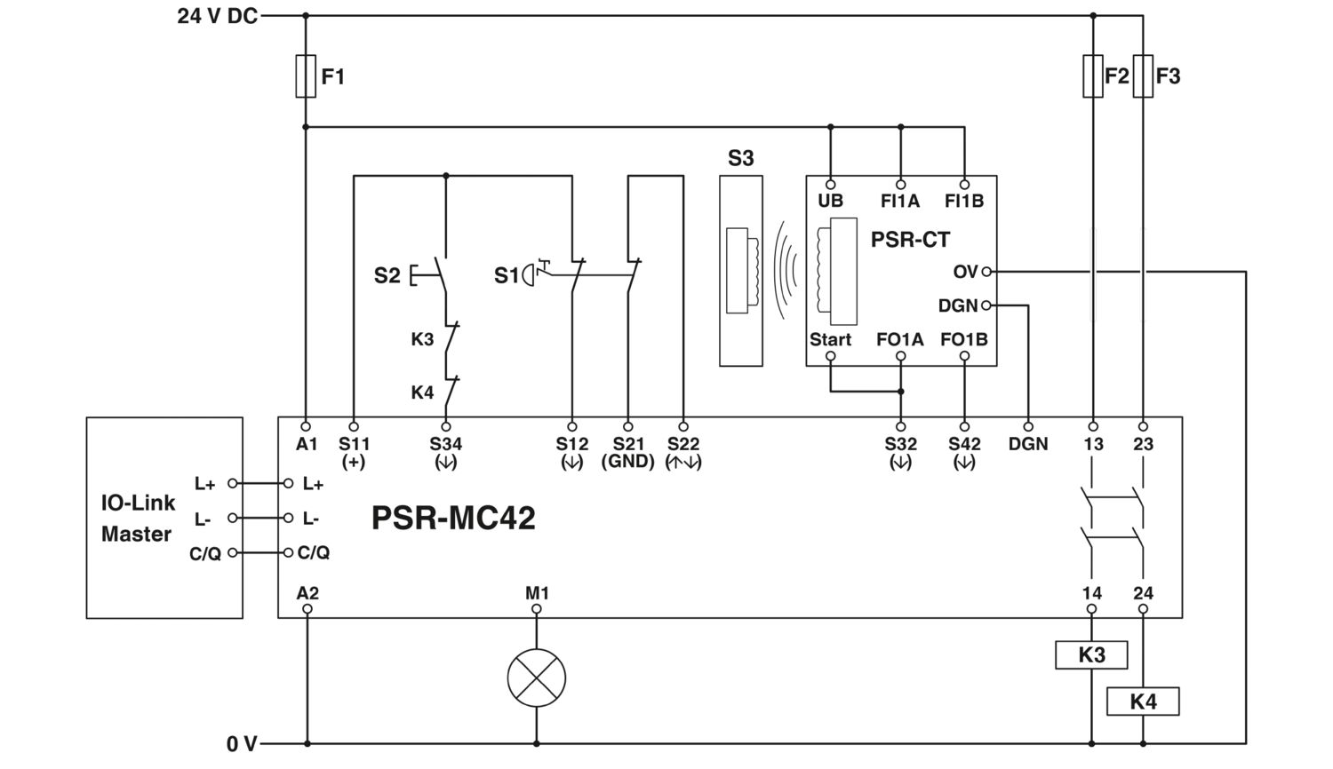
Safety relay with IO-Link for emergency stop, safety doors, and light grids, up to SIL 3, Cat. 4, PL e, 2 sensor circuits, automatic or manual, monitored start, 2 enabling current paths, 1 signal output, US = 24 V DC, plug-in screw terminal block
Free download available.
Downloads
Product details
Note on application | |
Note on application | Only for industrial use |
Product type | Safety relays |
Product family | PSRmini |
Application | Emergency stop |
Safety door | |
Light grid | |
Magnetic switch | |
Transponder | |
Control | 1 and 2 channel |
Relay type | Electromechanical relay with force-guided contacts in accordance with IEC/EN 61810-3 |
Insulation characteristics | |
Overvoltage category | II |
Degree of pollution | 2 |
Times | |
Typical response time | < 220 ms (automatic start) |
< 175 ms (manual, monitored start) | |
Typ. starting time with Us | < 250 ms (when controlled via A1) |
Typical release time | < 20 ms (on demand via the sensor circuit) |
< 20 ms (on demand via A1) | |
Restart time | < 1 s (Boot time) |
Recovery time | < 500 ms |
Start pulse length | ≥ 500 ms (manual start) |
Maximum power dissipation for nominal condition | 6.45 W (US = 30 V, UL = 30 V, I² = 72 A²) |
Nominal operating mode | 100% operating factor |
Rated insulation voltage | 320 V |
Rated surge voltage/insulation | See section “Insulation coordination” |
Supply | |
Designation | L+/L- |
Nominal voltage for I/O supply | 24 V DC -20 % / +25 % (Provided via the IO-Link interface of the IO-Link master.) |
Current consumption | typ. 16 mA |
Protective circuit | Serial protection against polarity reversal; Suppressor diode |
Supply | |
Designation | A1/A2 |
Rated control circuit supply voltage US | 19.2 V DC ... 30 V DC |
Rated control circuit supply voltage US | 24 V DC -20 % / +25 % (provide external protection) |
Rated control supply current IS | typ. 60 mA |
Power consumption at US | typ. 1.44 W |
Inrush current | typ. 2.5 A (Δt = 500 µs at Us) |
Filter time | 1 ms (at A1 in the event of voltage dips at Us) |
Protective circuit | Serial protection against polarity reversal; Suppressor diode |
Digital: Sensor circuit S0 (S12, S22) | |
Description of the input | safety-related sensor inputs |
Number of inputs | 2 |
Input voltage range "0" signal | 0 V DC ... 5 V DC (S12) |
For S22, see note in “Signal generator connection versions” section. | |
Input voltage range "1" signal | 11 V DC ... 30 V DC |
Input current range "0" signal | 0 mA ... 2 mA (S12, S22) |
Inrush current | < 5 mA (typ. with US at S12, Δt = 500 µs) |
< 5 mA (typ. with US at S22/24 V, Δt = 500 µs) | |
> -5 mA (typ. with US at S22/0 V, Δt = 500 µs) | |
Filter time | max. 1.5 ms (Test pulse width of low test pulses) |
Test pulse rate = 5 x Test pulse width | |
Deactivate the switch-on pulses for safety applications. | |
Concurrence | ∞ |
Max. permissible overall conductor resistance | 150 Ω |
Protective circuit | Suppressor diode |
Current consumption | < 5 mA (typ. with US at S12) |
< 5 mA (typ. with US at S22/24 V) | |
> -5 mA (typ. with US at S22/0 V) | |
Digital: Sensor circuit S1 (S32, S42) | |
Description of the input | safety-related sensor inputs |
Number of inputs | 2 |
Input voltage range "0" signal | 0 V DC ... 5 V DC |
Input voltage range "1" signal | 11 V DC ... 30 V DC |
Input current range "0" signal | 0 mA ... 2 mA |
Inrush current | < 20 mA (typ. with US) |
Filter time | max. 1.5 ms (Test pulse width of low test pulses) |
Test pulse rate = 5 x Test pulse width | |
Deactivate the switch-on pulses for safety applications. | |
Concurrence | ∞ |
Max. permissible overall conductor resistance | 150 Ω |
Protective circuit | Suppressor diode |
Current consumption | < 5 mA (typ. with US) |
Digital: Diagnostic input (DGN) | |
Description of the input | non-safety-related |
Number of inputs | 1 |
Input voltage range | 0 V DC ... 30 V DC |
Protective circuit | Suppressor diode |
Current consumption | typ. 30 mA |
Digital: Start circuit (S34) | |
Description of the input | NPN (manual start), PNP (autostart) |
Number of inputs | 1 |
Input voltage range "1" signal | 19.2 V DC ... 30 V DC (manual start, autostart: 0 V) |
Inrush current | < 10 mA (typ. with US, Δt = 100 ms) |
Max. permissible overall conductor resistance | 150 Ω |
Protective circuit | Suppressor diode |
Current consumption | < 5 mA (typ. with US at S34/24 V) |
> -5 mA (typ. with US at S34/0 V) | |
IO-Link | |
Designation | IO-Link |
Transmission speed | 230 kbps (COM3) |
Cycle Time | 5 ms |
Process data update | 5 ms |
Amount of process data | max. 31 Byte (Input data) |
max. 16 Byte (Output data) | |
Description of the input | IO-Link switching and communication cable |
Number of inputs | 1 |
Connection method | Screw connection |
Connection technology | 3-conductor |
Number of ports | 1 |
Port type | Class A |
Relay: Enabling current path (13/14, 23/24) | |
Output description | safety-related N/O contacts |
2 NO contacts each in series, without delay, floating | |
Number of outputs | 2 (undelayed) |
Contact switching type | 2 enabling current paths |
Contact material | AgSnO2 |
Switching voltage | min. 12 V AC/DC |
max. 250 V AC/DC | |
Switching capacity | min. 60 mW |
Inrush current | min. 3 mA |
max. 6 A | |
Limiting continuous current | 6 A |
Sq. Total current | 72 A2 (observe derating) |
Switching frequency | 0.1 Hz |
Mechanical service life | 10x 106 cycles |
Output fuse | 6 A gL/gG |
4 A gL/gG (for low-demand applications) | |
Signal: M1 | |
Output description | PNP |
non-safety-related | |
Number of outputs | 1 |
Voltage | approx. 22 V DC (Us - 2 V) |
Current | max. 100 mA |
Maximum inrush current | 500 mA (Δt = 1 ms at Us) |
Protective circuit | Suppressor diode |
Connection technology | |
pluggable | yes |
Conductor connection | |
Connection method | Screw connection |
Conductor cross section rigid | 0.2 mm² ... 2.5 mm² |
Conductor cross section flexible | 0.2 mm² ... 2.5 mm² |
Conductor cross-section AWG | 24 ... 12 |
Stripping length | 7 mm |
Screw thread | M3 |
Tightening torque | 0.5 Nm ... 0.6 Nm |
Status display | 5 x LED (green) |
Operating voltage display | 1 x LED (green, yellow, red) |
Width | 17.5 mm |
Height | 112.2 mm |
Depth | 114.5 mm |
Color (Housing) | yellow (RAL 1018) |
Housing material | PA |
Safety data | |
Stop category | 0 |
Safety data: EN ISO 13849 | |
Category | 4 |
Performance level (PL) | e (4 A DC13; 5 A AC15; 8760 switching cycles/year) |
Safety data: IEC 61508 - High demand | |
Safety Integrity Level (SIL) | 3 |
Safety data: IEC 61508 - Low demand | |
Safety Integrity Level (SIL) | 3 |
Safety data: EN IEC 62061 | |
Safety Integrity Level (SIL) | 3 |
Ambient conditions | |
Degree of protection | IP20 |
Min. degree of protection of inst. location | IP54 |
Ambient temperature (operation) | -25 °C ... 60 °C (observe derating) |
Ambient temperature (storage/transport) | -40 °C ... 85 °C |
Maximum altitude | ≤ 2000 m (Above sea level) |
Max. permissible humidity (storage/transport) | 75 % (on average, 85% infrequently, non-condensing) |
Max. permissible relative humidity (operation) | 75 % (on average, 85% infrequently, non-condensing) |
Shock | 15g |
Vibration (operation) | 10 Hz ... 150 Hz, amplitude 0.15 mm, 2g |
CE | |
Identification | CE-compliant |
Mounting type | DIN rail mounting |
Assembly note | See derating curve |
Mounting position | vertical or horizontal |
Item number | 2702901 |
Packing unit | 1 pc |
Minimum order quantity | 1 pc |
Sales key | DNA |
Product key | DNA181 |
Catalog page | Page 224 (C-6-2019) |
GTIN | 4055626458540 |
Weight per piece (including packing) | 187.65 g |
Weight per piece (excluding packing) | 157.28 g |
Customs tariff number | 85371098 |
Country of origin | DE |
ECLASS
ECLASS-13.0 | 27371819 |
ETIM
ETIM 9.0 | EC001449 |
UNSPSC
UNSPSC 21.0 | 39122200 |
EU RoHS | |
Fulfills EU RoHS substance requirements | Yes |
Exemption | 7(a), 7(c)-I |
China RoHS | |
Environment friendly use period (EFUP) |
EFUP-50
An article-related China RoHS declaration table can be found in the download area for the respective article under "Manufacturer declaration". For all articles with EFUP-E, no China RoHS declaration table issued and required.
|
EU REACH SVHC | |
REACH candidate substance (CAS No.) | Lead (CAS: 7439-92-1) |
SCIP | 06c37c05-4d86-4236-997e-0585da70bfa9 |
Compatible products
-
PSR-CT-C-SEN-1-8 - Safety switch sensor 2702972
-
PSR-CT-M-SEN-1-8 - Safety switch sensor 2702975
-
PSR-CT-F-SEN-1-8 - Safety switch sensor 2702976
-
PSR-CT-C-ACT - Safety switch actuator 2702973
-
IOL-CONF - Configuration and diagnostic software 1083065
-
CRIMPFOX 6 - Crimping pliers 1212034
-
AXL E PN IOL4/4 EF M12 6M-L - Communication module 1300926
-
AXL F IOL8 2H - Communication module 1027843
-
AXL SE IOL4 - Communication module 1088132
Your advantages
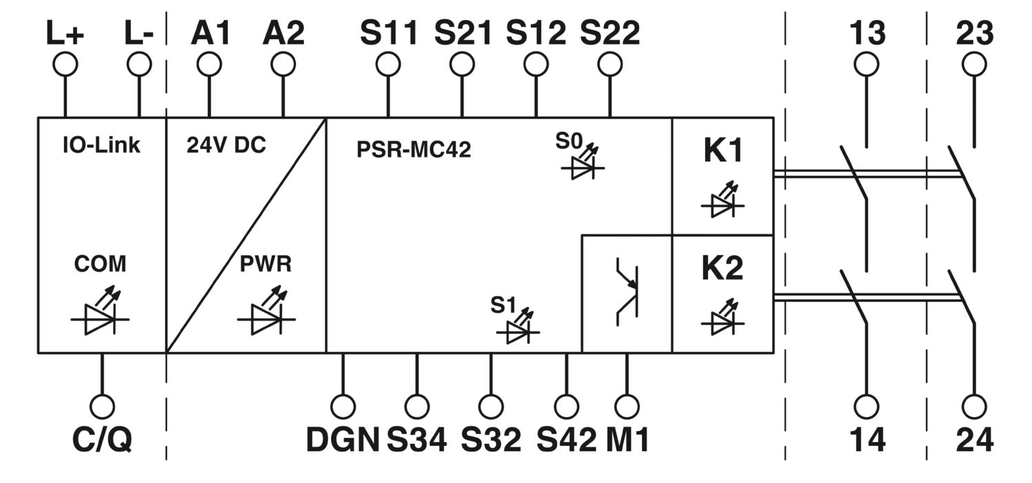
2 enabling current paths, 1 digital signal output
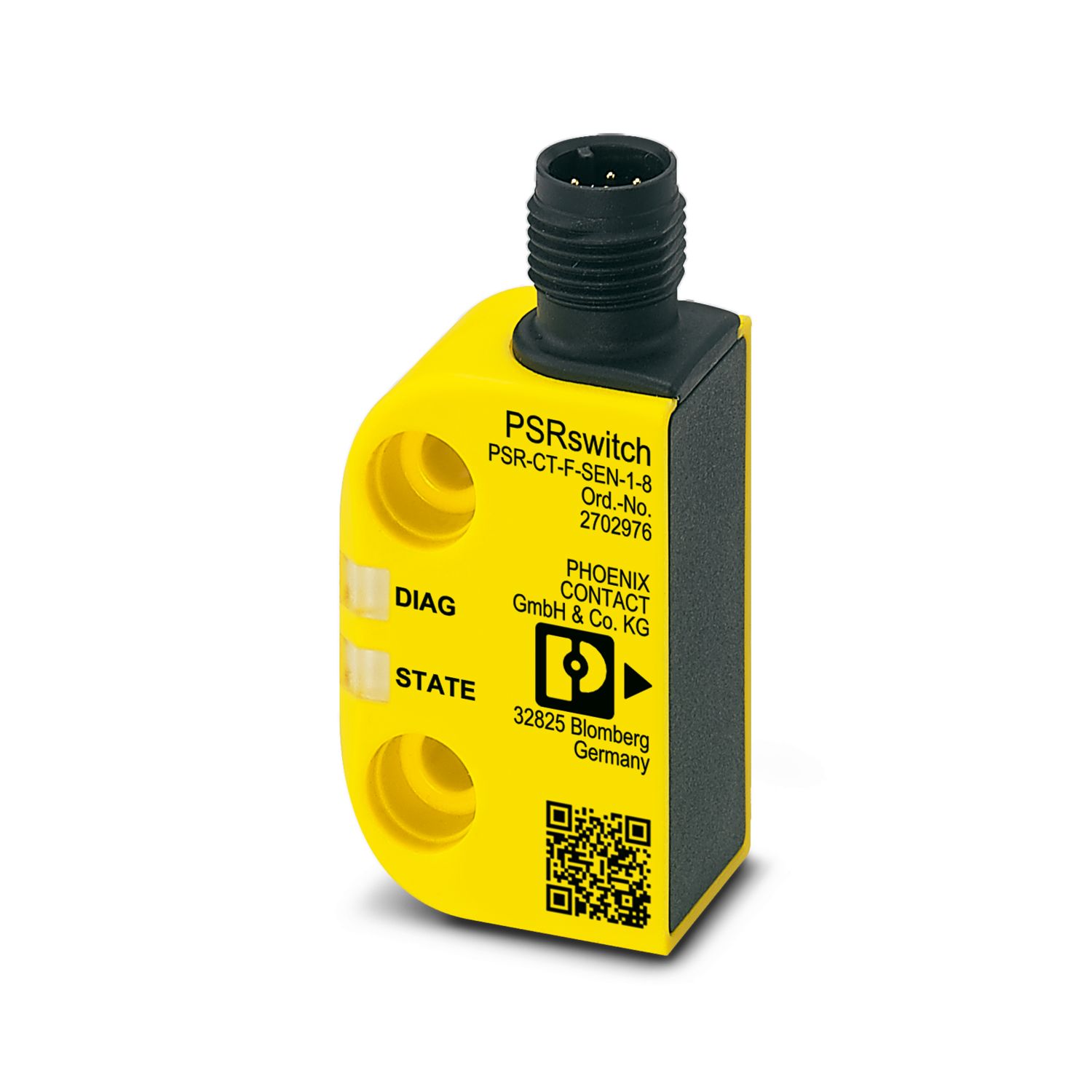
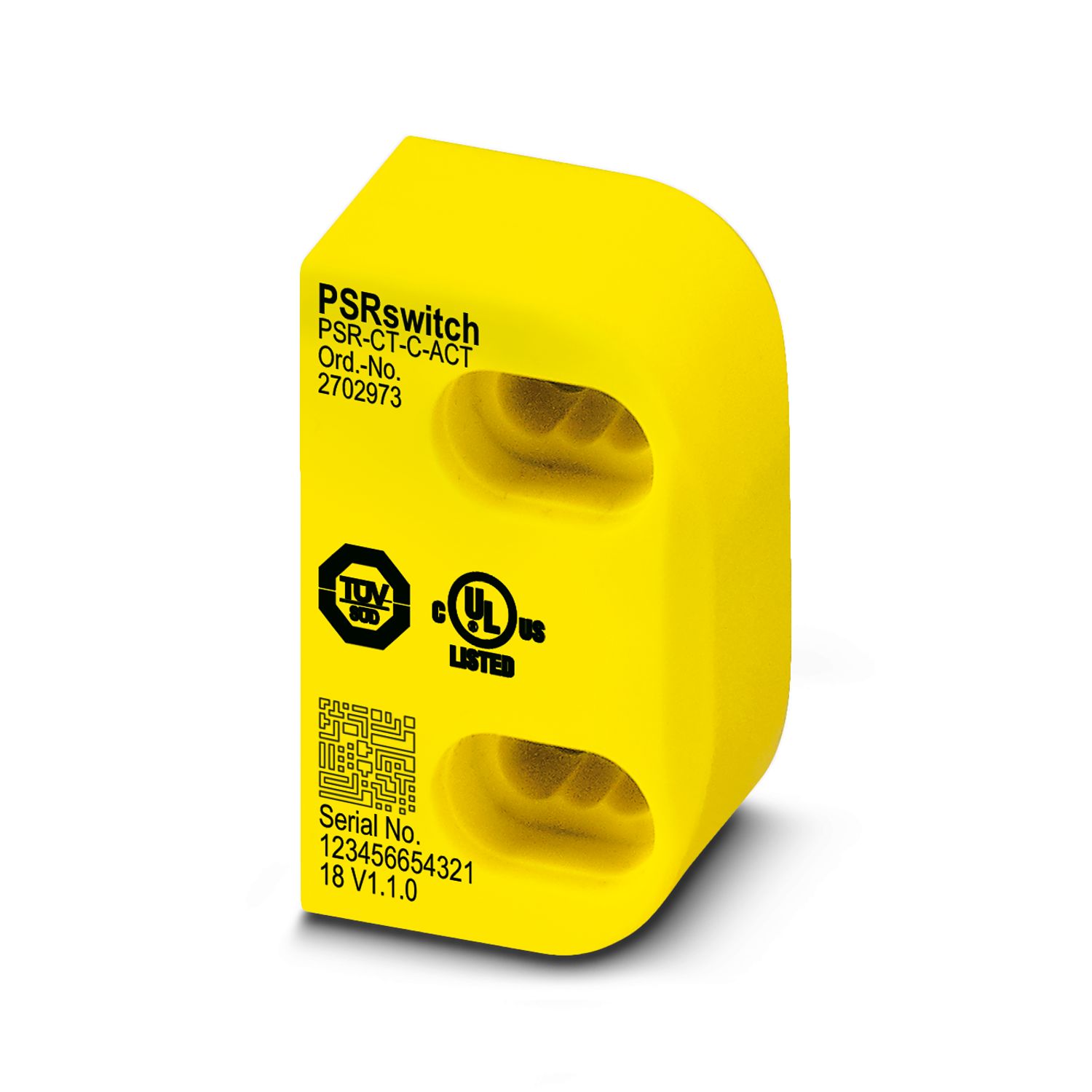
Diagnostic data via IO-Link in combination with PSR-CT safety switches
For emergency stop and safety door monitoring, plus evaluation of light grids
Automatic and manual activation
1- and 2-channel control
2 sensor circuits
Up to Cat. 4/PL e in accordance with ISO 13849-1, SIL 3 in accordance with EN IEC 62061, SIL 3 in accordance with IEC 61508