PSR-MC38-2NO-1DO-24DC-SC
-
Safety relays
1009831
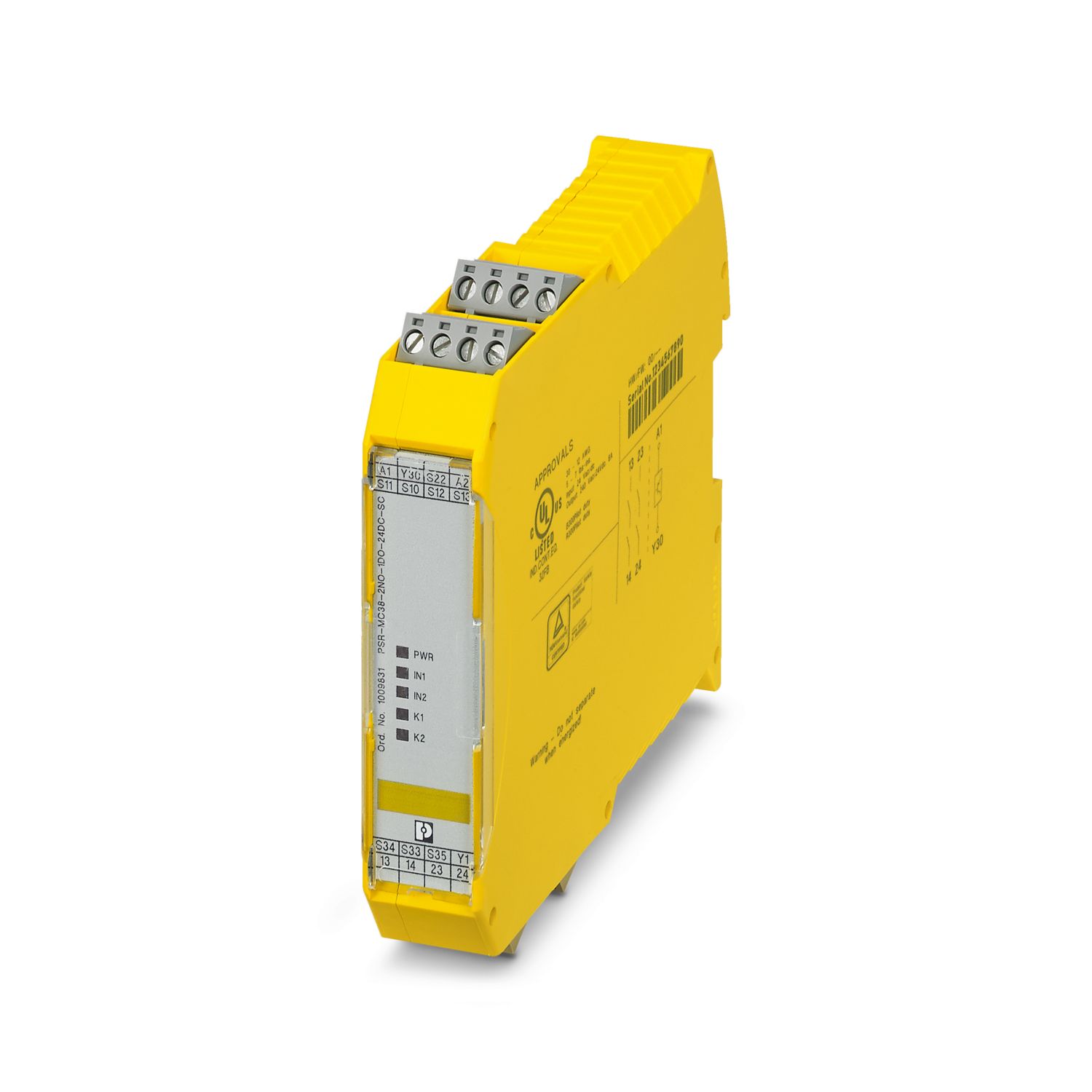
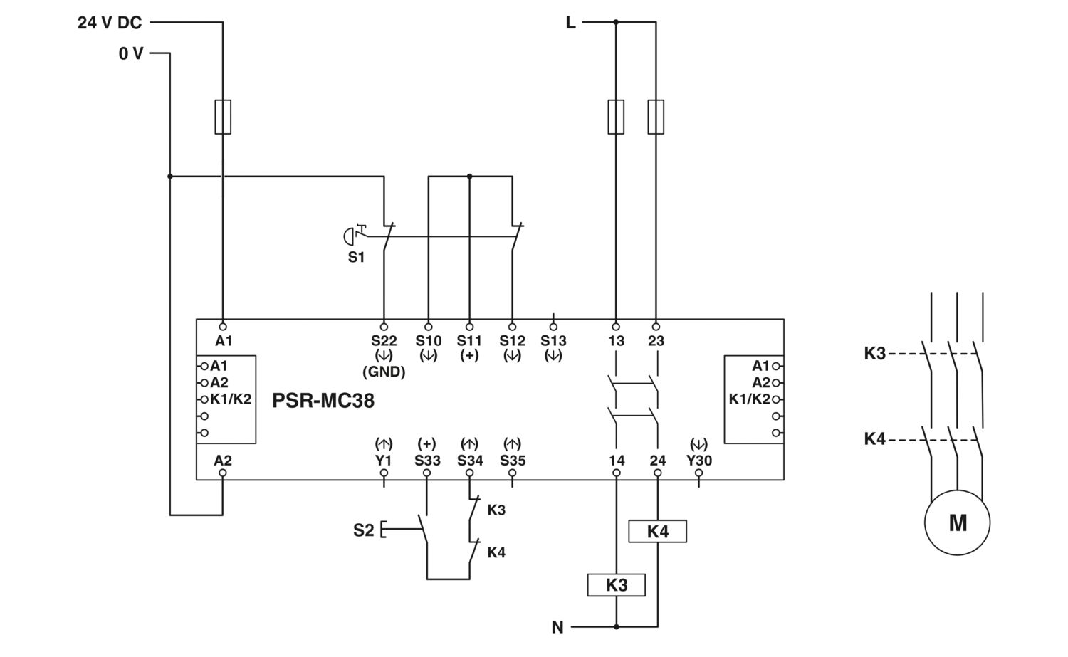
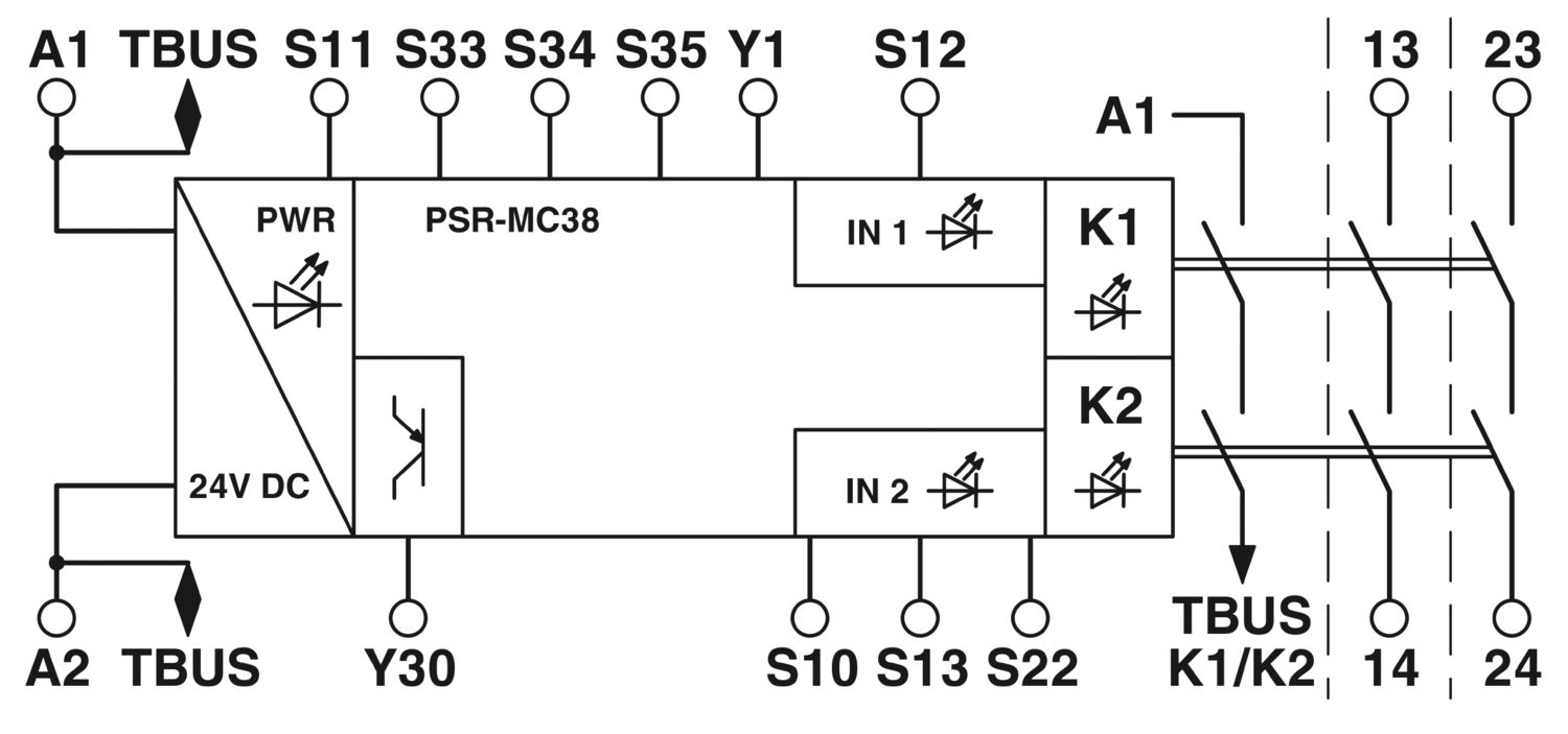
Safety relay for emergency stop, safety doors and light grids up to SIL 3, Cat. 4, PL e, 1- or 2-channel operation, automatic or manual, monitored start, 2 enabling current paths, 1 signal output, TBUS interface, US = 24 V DC, pluggable screw terminal block
Free download available.
Downloads
Product details
Note on application | |
Note on application | Only for industrial use |
Product type | Safety relays |
Product family | PSRmini |
Application | Emergency stop |
Safety door | |
Light grid | |
Magnetic switch | |
Transponder | |
Control | 1 and 2 channel |
Relay type | Electromechanical relay with force-guided contacts in accordance with IEC/EN 61810-3 |
Insulation characteristics | |
Overvoltage category | III |
Degree of pollution | 2 |
Times | |
Typical response time | 200 ms (automatic start) |
30 ms (manual, monitored start) | |
Typ. starting time with Us | 200 ms (when controlled via A1) |
Typical release time | 25 ms (when actuation is via the sensor circuit) |
60 ms (when controlled via A1) | |
Restart time | < 1 s (Boot time) |
Recovery time | < 500 ms |
Maximum power dissipation for nominal condition | 16.6 W (at US = 26.4 V, IL² = 72 A²) |
Nominal operating mode | 100% operating factor |
Rated insulation voltage | 250 V |
Rated surge voltage/insulation | See data sheet, section “Insulation coordination”. |
Supply | |
Designation | A1/A2 |
Rated control circuit supply voltage US | 20.4 V DC ... 26.4 V DC |
Rated control circuit supply voltage US | 24 V DC -15 % / +10 % (provide external protection) |
Rated control supply current IS | typ. 75 mA |
Power consumption at US | typ. 1.8 W |
Inrush current | < 4 A (Δt = 3 ms at Us) |
Filter time | 20 ms (at A1 in the event of voltage dips at Us) |
Protective circuit | Serial protection against polarity reversal; Suppressor diode |
Digital: Sensor circuit (S10, S12, S13, S22) | |
Description of the input | safety-related sensor inputs |
Number of inputs | 4 |
Input voltage range "1" signal | 20.4 V DC ... 26.4 V DC |
Inrush current | < 40 mA (typ. with US at S10) |
< 300 mA (typ. with US at S12, Δt = 150 ms) | |
< 3 mA (typ. with US at S13) | |
> -300 mA (typ. with US at S22, Δt = 150 ms) | |
Filter time | 2 ms (At S10, S12, S13; test pulse width of low test pulses) |
1 s (At S10, S12, S13; test pulse rate of low test pulses) | |
No brightness test pulses / high test pulses permitted. | |
Concurrence | ∞ |
Max. permissible overall conductor resistance | 50 Ω |
Protective circuit | Suppressor diode |
Current consumption | 40 mA (typ. with US at S10) |
45 mA (typ. with US at S12) | |
3 mA (typ. with US at S13) | |
-35 mA (typ. with US at S22, Δt = 150 ms) | |
Digital: Start circuit (Y1, S34, S35) | |
Description of the input | non-safety-related |
Number of inputs | 3 |
Input voltage range "1" signal | 20.4 V DC ... 26.4 V DC |
Inrush current | < 60 mA (typ. with US at Y1, Δt = 150 ms) |
< 270 mA (typ. with US at S34, Δt = 15 ms) | |
< 80 mA (typ. with US at S35, Δt = 25 ms) | |
Filter time | No darkness test pulses / low test pulses permitted. No brightness test pulses / high test pulses permitted. |
Max. permissible overall conductor resistance | 50 Ω |
Protective circuit | Suppressor diode |
Current consumption | typ. 10 mA (typ. with US at Y1) |
typ. 34 µA (typ. with US at S35) |
Relay: Enabling current path (13/14, 23/24) | |
Output description | safety-related N/O contacts |
2 NO contacts each in series, without delay, floating | |
Number of outputs | 2 (undelayed) |
Contact switching type | 2 enabling current paths |
Contact material | AgSnO2 |
Switching voltage | min. 10 V AC/DC |
max. 250 V AC/DC (Observe the load curve) | |
Switching capacity | min. 100 mW |
Inrush current | min. 10 mA |
max. 6 A | |
Limiting continuous current | 6 A |
Sq. Total current | 72 A2 (observe derating) |
Switching frequency | max. 0.5 Hz |
Mechanical service life | 10x 106 cycles |
Output fuse | 10 A gL/gG |
4 A gL/gG (for low-demand applications) | |
Signal: Y30 | |
Output description | PNP |
non-safety-related | |
Number of outputs | 1 |
Voltage | approx. 23.9 V DC (Us - 0.1 V) |
Current | max. 100 mA |
Maximum inrush current | 500 mA (Δt = 1 ms at Us) |
Protective circuit | Suppressor diode |
Connection technology | |
pluggable | yes |
Conductor connection | |
Connection method | Screw connection |
Conductor cross section rigid | 0.2 mm² ... 2.5 mm² |
Conductor cross section flexible | 0.2 mm² ... 2.5 mm² |
Conductor cross-section AWG | 24 ... 12 |
Stripping length | 7 mm |
Screw thread | M3 |
Tightening torque | 0.5 Nm ... 0.6 Nm |
Status display | 4 x LED (green) |
Operating voltage display | 1 x LED (green) |
Width | 22.5 mm |
Height | 112.2 mm |
Depth | 114.5 mm |
Color (Housing) | yellow (RAL 1018) |
Housing material | PA |
Safety data | |
Stop category | 0 |
Safety data: EN ISO 13849 | |
Category | 4 (5 A DC13; 5 A AC15; 8760 switching cycles/year) |
Performance level (PL) | e |
Safety data: IEC 61508 - High demand | |
Safety Integrity Level (SIL) | 3 |
Safety data: IEC 61508 - Low demand | |
Safety Integrity Level (SIL) | 3 |
Safety data: EN IEC 62061 | |
Safety Integrity Level (SIL) | 3 |
Ambient conditions | |
Degree of protection | IP20 |
Min. degree of protection of inst. location | IP54 |
Ambient temperature (operation) | -20 °C ... 55 °C (observe derating) |
Ambient temperature (storage/transport) | -40 °C ... 70 °C |
Maximum altitude | ≤ 2000 m (Above sea level) |
Max. permissible humidity (storage/transport) | 75 % (on average, 85% infrequently, non-condensing) |
Max. permissible relative humidity (operation) | 75 % (on average, 85% infrequently, non-condensing) |
Shock | 15g |
Vibration (operation) | 10 Hz ... 150 Hz, 2g |
CE | |
Identification | CE-compliant |
Mounting type | DIN rail mounting |
Assembly note | See derating curve |
Mounting position | vertical or horizontal |
Item number | 1009831 |
Packing unit | 1 pc |
Minimum order quantity | 1 pc |
Sales key | DNA |
Product key | DNA181 |
GTIN | 4055626482705 |
Weight per piece (including packing) | 212.33 g |
Weight per piece (excluding packing) | 169.38 g |
Customs tariff number | 85371098 |
Country of origin | DE |
ECLASS
ECLASS-13.0 | 27371819 |
ETIM
ETIM 9.0 | EC001449 |
UNSPSC
UNSPSC 21.0 | 39122200 |
EU RoHS | |
Fulfills EU RoHS substance requirements | Yes |
Exemption | 7(a), 7(c)-I |
China RoHS | |
Environment friendly use period (EFUP) |
EFUP-50
An article-related China RoHS declaration table can be found in the download area for the respective article under "Manufacturer declaration". For all articles with EFUP-E, no China RoHS declaration table issued and required.
|
EU REACH SVHC | |
REACH candidate substance (CAS No.) | Lead (CAS: 7439-92-1) |
SCIP | 4d970b5f-c2f8-453e-aee7-b21159620cd5 |
Compatible products
-
PSR-TBUS - DIN rail bus connector 2890425
-
ME 17,5 TBUS 1,5/ 5-ST-3,81 GN - DIN rail bus connector 2709561
-
ELR H5-IES-PT- 24DC/500AC-3-P - Hybrid motor starter 2909556
-
ELR H5-IES-PT- 24DC/500AC-9-P - Hybrid motor starter 2909554
-
ELR H5-IS-SC- 24DC/500AC-3-P - Hybrid motor starter 2908699
-
ELR H5-IS-SC- 24DC/500AC-9-P - Hybrid motor starter 2908697
-
ELR H5-IS-PT- 24DC/500AC-3-P - Hybrid motor starter 2909569
-
ELR H5-IS-PT- 24DC/500AC-9-P - Hybrid motor starter 2909567
-
ELR H3-IS-SC- 24DC/500AC-3-P - Hybrid motor starter 2908700
-
ELR H3-IS-SC- 24DC/500AC-9-P - Hybrid motor starter 2908698
-
ELR H3-IS-PT- 24DC/500AC-3-P - Hybrid motor starter 2909570
-
ELR H3-IS-PT- 24DC/500AC-9-P - Hybrid motor starter 2909568
-
ELR-TBUS-22,5-P - DIN rail bus connector 2203861
-
PSR-TBUS - 1PCS - DIN rail bus connector 1326060
-
CRIMPFOX 6 - Crimping pliers 1212034
Your advantages
Up to Cat. 4/PL e in accordance with ISO 13849-1, SIL 3 in accordance with EN IEC 62061, SIL 3 in accordance with IEC 61508
1- and 2-channel control
2 enabling current paths, 1 digital signal output
For emergency stop and safety door monitoring, plus evaluation of light grids
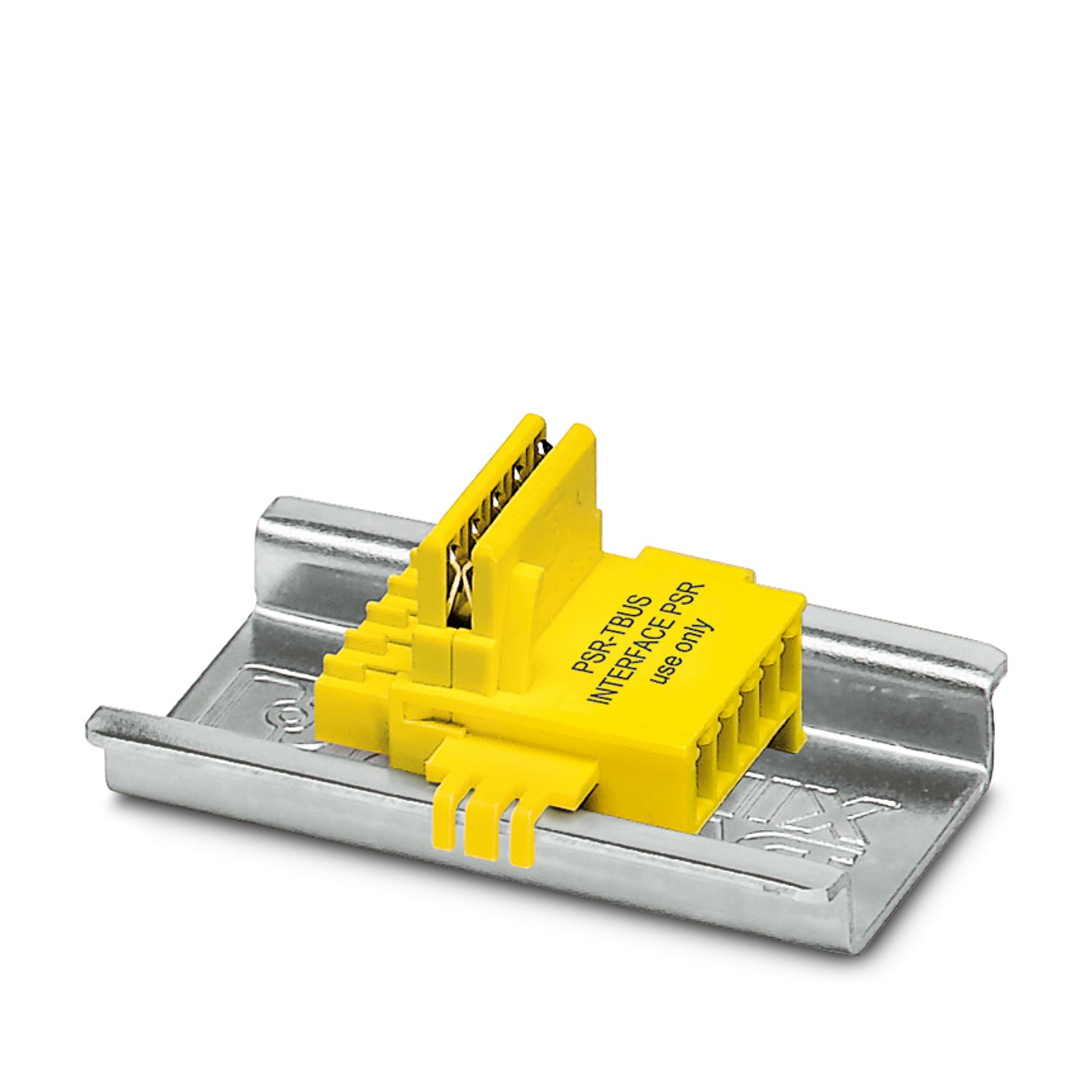
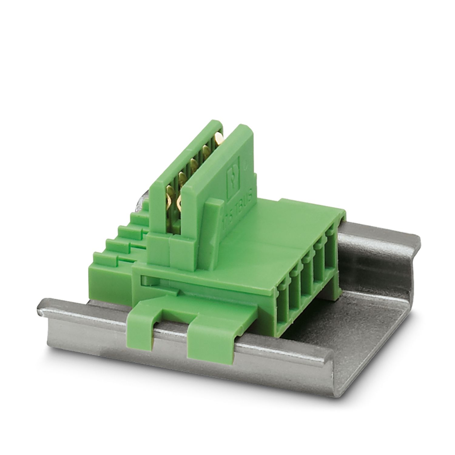
TBUS interface for connecting CONTACTRON hybrid motor starters and MINI POWER power supplies