
In the power range of up to 100 W, QUINT POWER provides superior system availability in the smallest size. Preventative function monitoring and exceptional power reserves are available for applications in the low-power range.
QUINT4-PS/1AC/24DC/2.5/SC
-
Power supply
2904598
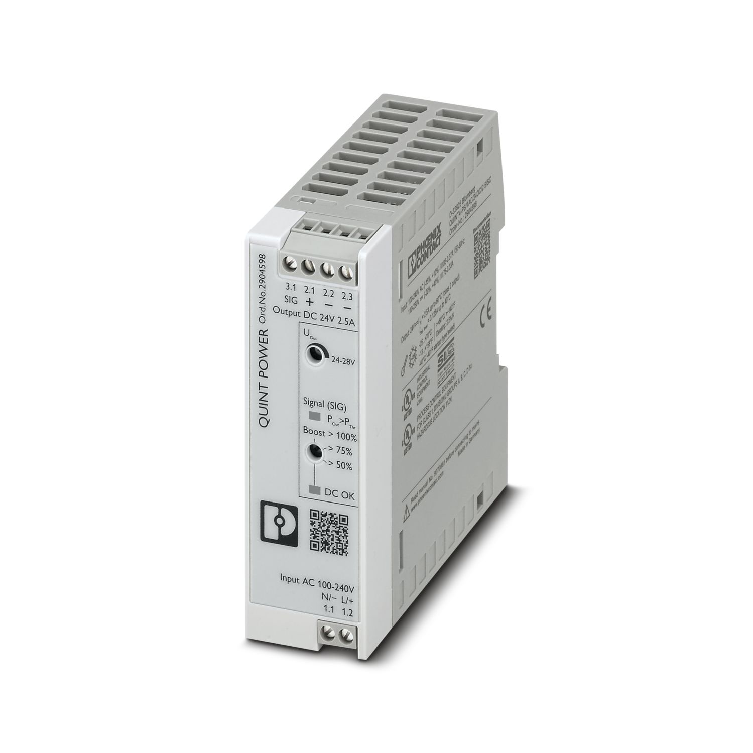
Primary-switched power supply unit QUINT POWER, Screw connection, DIN rail mounting, input: 1-phase, output: 24 V DC / 2.5 A. Alternative item: 2909576
Product details
| AC operation | |
| Input voltage range | 100 V AC ... 240 V AC -15 % ... +10 % |
| Electric strength, max. | 300 V AC 30 s |
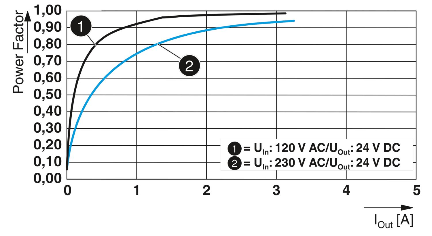
| Typical national grid voltage | 120 V AC |
| 230 V AC | |
| Voltage type of supply voltage | AC |
| Inrush current | typ. 10 A (at 25 °C) |
| Inrush current integral (I2t) | < 0.1 A2s |
| Inrush current limitation | 4.3 A (after 1 ms) |
| < 10 A | |
| Frequency range (fN) | 50 Hz ... 60 Hz -10 % ... +10 % |
| 16.7 Hz (acc. to EN 50163) | |
| Mains buffering time | typ. 54 ms (120 V AC) |
| typ. 54 ms (230 V AC) | |
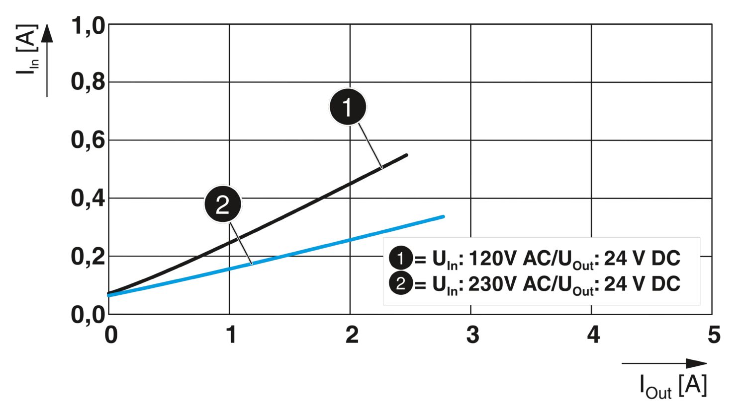
| Current consumption | 0.85 A (100 V AC) |
| 0.7 A (120 V AC) | |
| 0.39 A (230 V AC) | |
| 0.37 A (240 V AC) | |
| Nominal power consumption | 71 VA |
| Protective circuit | Transient surge protection; Varistor |
| Typical response time | 500 ms |
| Input fuse | 3.15 A (slow-blow, internal) |
| Recommended breaker for input protection | 6 A ... 16 A (Characteristic B, C or comparable) |
| Discharge current to PE | < 0.25 mA (264 V AC, 60 Hz) |
| 0.22 mA (264 V AC, 60 Hz) | |
| DC operation | |
| Input voltage range | 110 V DC ... 250 V DC -20 % ... +40 % |
| Voltage type of supply voltage | DC |
| Current consumption | 0.75 A (110 V DC) |
| 0.33 A (250 V DC) | |
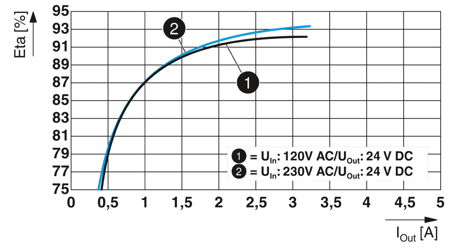
| Efficiency | typ. 91.9 % (120 V AC) |
| typ. 92.6 % (230 V AC) | |
| Output characteristic | U/I Advanced |
| Nominal output voltage | 24 V DC |
| Setting range of the output voltage (USet) | 24 V DC ... 28 V DC (constant capacity) |
| Nominal output current (IN) | 2.5 A |
| Static Boost (IStat.Boost) | 3.125 A (≤ 40 °C) |
| Dynamic Boost (IDyn.Boost) | 5 A (≤60 °C (5 s), Input <150 V AC Derating 0.5 %/V) |
| Derating | > 60 °C (2.5 %/K) |
| Feedback voltage resistance | ≤ 35 V DC |
| Protection against overvoltage at the output (OVP) | ≤ 32 V DC |
| Control deviation | < 0.5 % (Static load change 10 % ... 90 %) |
| < 2 % (Dynamic load change 10 % ... 90 %, (10 Hz)) | |
| < 0.1 % (change in input voltage ±10 %) | |
| Residual ripple | < 40 mVPP (with nominal values) |
| Short-circuit-proof | yes |
| No-load proof | yes |
| Output power | 60 W |
| 75 W | |
| 120 W | |
| Maximum no-load power dissipation | < 1 W (230 V AC) |
| < 1 W (120 V AC) | |
| Power loss nominal load max. | < 5 W (230 V AC) |
| < 5 W (120 V AC) | |
| Crest factor | typ. 1.69 (120 V AC) |
| typ. 1,82 (230 V AC) | |
| Rise time | 50 ms (UOut = 10 % ... 90 %) |
| Connection in parallel | yes, for redundancy and increased capacity |
| Connection in series | yes |
| Signal (configurable) | |
| Digital | 0 V DC 24 V DC 30 mA |
| Default | 24 V DC 30 mA 24 V DC for UOut > 0.9 x USet |
| Input | |
| Connection method | Screw connection |
| Conductor cross-section, rigid min. | 0.14 mm² |
| Conductor cross-section, rigid max. | 2.5 mm² |
| Conductor cross-section flexible min. | 0.14 mm² |
| Conductor cross-section flexible max. | 2.5 mm² |
| Single conductor/terminal point, stranded, with ferrule, min. | 0.25 mm² |
| Single conductor/terminal point, stranded, with ferrule, max. | 2.5 mm² |
| Conductor cross-section AWG min. | 26 |
| Conductor cross-section AWG max. | 14 |
| Stripping length | 8 mm |
| Tightening torque, min | 0.5 Nm |
| Tightening torque max | 0.6 Nm |
| Output | |
| Connection method | Screw connection |
| Conductor cross-section, rigid min. | 0.14 mm² |
| Conductor cross-section, rigid max. | 2.5 mm² |
| Conductor cross-section flexible min. | 0.14 mm² |
| Conductor cross-section flexible max. | 2.5 mm² |
| Single conductor/terminal point, stranded, with ferrule, min. | 0.25 mm² |
| Single conductor/terminal point, stranded, with ferrule, max. | 2.5 mm² |
| Conductor cross-section AWG min. | 26 |
| Conductor cross-section AWG max. | 14 |
| Stripping length | 8 mm |
| Tightening torque, min | 0.5 Nm |
| Tightening torque max | 0.6 Nm |
| Signal | |
| Connection method | Screw connection |
| Conductor cross-section, rigid min. | 0.14 mm² |
| Conductor cross-section, rigid max. | 2.5 mm² |
| Conductor cross-section flexible min. | 0.14 mm² |
| Conductor cross-section flexible max. | 2.5 mm² |
| Single conductor/terminal point, stranded, with ferrule, min. | 0.25 mm² |
| Single conductor/terminal point, stranded, with ferrule, max. | 2.5 mm² |
| Conductor cross-section AWG min. | 26 |
| Conductor cross-section AWG max. | 14 |
| Stripping length | 8 mm |
| Tightening torque, min | 0.5 Nm |
| Tightening torque max | 0.6 Nm |
| Types of signaling | LED |
| Signal output | |
| POut | > PThr (LED lights up yellow, output power > PThr, depending on the rotary selector switch setting) |
| UOut | > 0.9 x USet (LED lights up green) |
| < 0.9 x USet (LED flashes green) | |
| Number of phases | 1 |
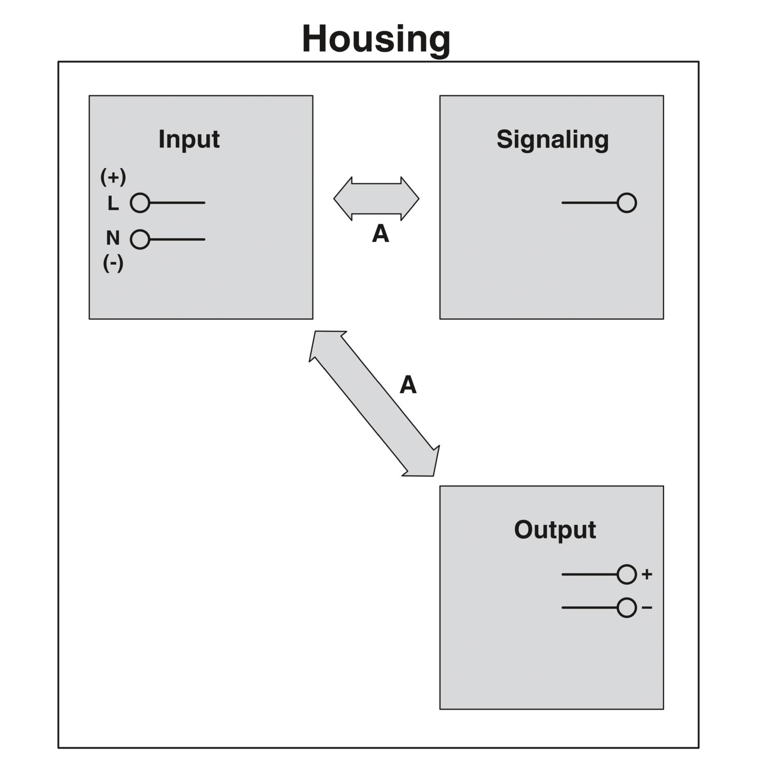
| Insulation voltage input/output | 4 kV AC (type test) |
| 3 kV AC (routine test) | |
| Switching frequency | 4.00 kHz ... 70.00 kHz (Auxiliary converter stage) |
| 30.00 kHz ... 150.00 kHz (PFC stage) | |
| 70.00 kHz ... 150.00 kHz (Main converter stage) |
| Product family | QUINT POWER |
| MTBF (IEC 61709, SN 29500) | > 1347000 h (25 °C) |
| > 734000 h (40 °C) | |
| > 295000 h (60 °C) | |
| Environmental protection directive | RoHS Directive 2011/65/EU |
| WEEE | |
| Reach | |
| Insulation characteristics | |
| Protection class | II |
| Degree of pollution | 2 |
| Life expectancy (electrolytic capacitors) | |
| Current | 2.5 A |
| Temperature | 40 °C |
| Time | 148000 h |
| Additional text | 120 V AC |
| Life expectancy (electrolytic capacitors) | |
| Current | 2.5 A |
| Temperature | 40 °C |
| Time | 153000 h |
| Additional text | 230 V AC |
| Life expectancy (electrolytic capacitors) | |
| Current | 2.5 A |
| Temperature | 25 °C |
| Time | 419000 h |
| Additional text | 120 V AC |
| Life expectancy (electrolytic capacitors) | |
| Current | 2.5 A |
| Temperature | 25 °C |
| Time | 432000 h |
| Additional text | 230 V AC |
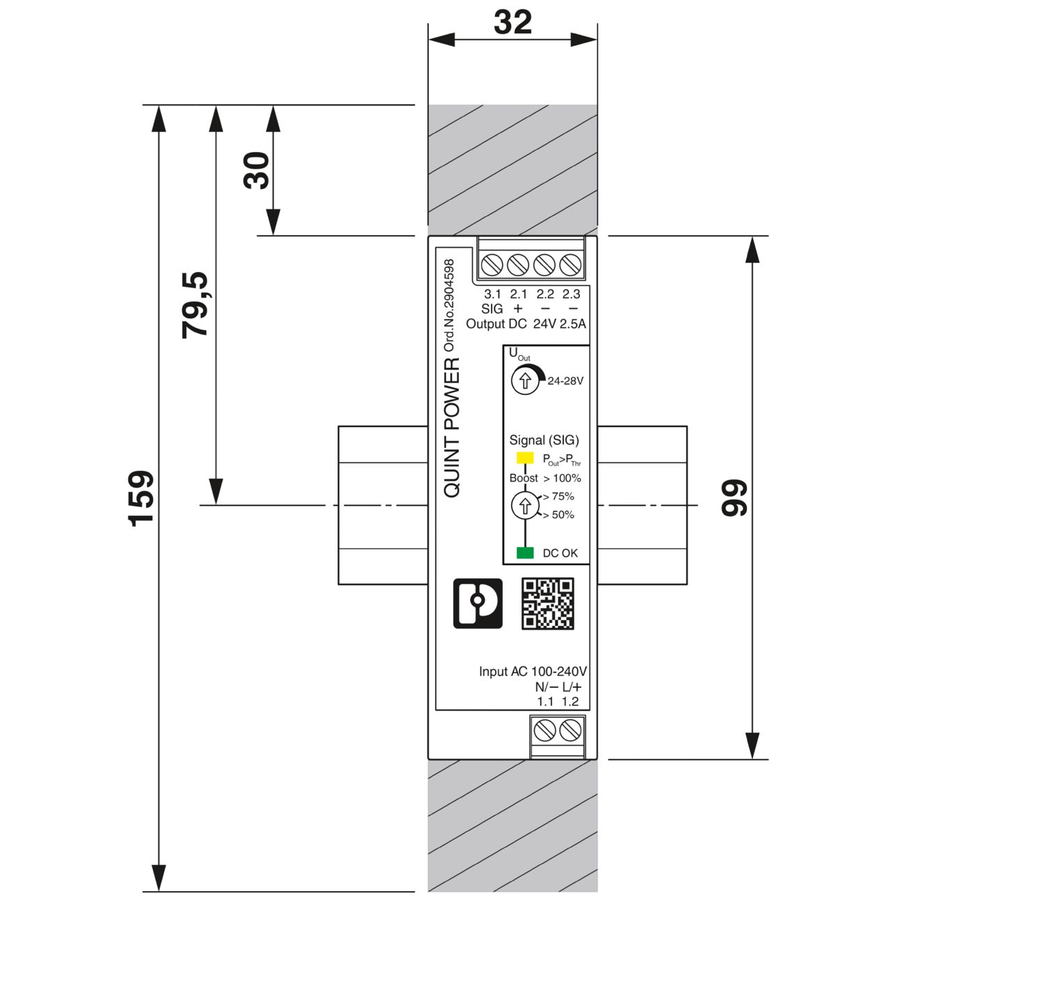
| Dimensional drawing |
|
| Width | 32 mm |
| Height | 99 mm |
| Depth | 90 mm |
| Installation dimensions | |
| Installation distance right/left (active) | 15 mm / 15 mm (POut ≥50% ) |
| Installation distance right/left (passive) | 5 mm / 5 mm (POut ≥50% ) |
| Installation distance top/bottom (active) | 30 mm / 30 mm (POut ≥50% ) |
| Installation distance top/bottom (passive) | 30 mm / 30 mm (POut ≥50% ) |
| Installation distance top/bottom (active, passive) | 30 mm / 30 mm (POut ≤50 %) |
| Mounting type | DIN rail mounting |
| Assembly note | DIN rail mounting |
| With protective coating | no |
| Flammability rating according to UL 94 (housing / terminal blocks) | V0 |
| Housing material | Plastic |
| Type of housing | Polycarbonate |
| Hood version | Polycarbonate |
| Ambient conditions | |
| Degree of protection | IP20 |
| Ambient temperature (operation) | -25 °C ... 70 °C (> 60 °C Derating: 2,5 %/K) |
| Ambient temperature (storage/transport) | -40 °C ... 85 °C |
| Ambient temperature (start-up type tested) | -40 °C |
| Maximum altitude | ≤ 5000 m (> 2000 m, observe derating) |
| Climatic class | 3K3 (in acc. with EN 60721) |
| Max. permissible relative humidity (operation) | ≤ 95 % (at 25 °C, non-condensing) |
| Shock | 18 ms, 30g, in each space direction (according to IEC 60068-2-27) |
| Vibration (operation) | < 15 Hz, ±2.5 mm amplitude; 15 Hz ... 100 Hz: 2.3 g 90 Min. (in accordance with IEC 60068-2-6) |
| Temp code | T4 (-25 ... +70 °C; > 60 °C, Derating: 2,5 %/K) |
| Rail applications | EN 50121-3-2 |
| EN 50121-4 | |
| EN 50121-5 | |
| IEC 62236-3-2 | |
| IEC 62236-4 | |
| IEC 62236-5 | |
| Standard – Limitation of mains harmonic currents | EN 61000-3-2 |
| Standard - Electrical safety | IEC 61010-2-201 (SELV) |
| Standard – Safety extra-low voltage | IEC 61010-1 (SELV) |
| IEC 61010-2-201 (PELV) | |
| Standard - Safe isolation | IEC 61558-2-16 |
| IEC 61010-2-201 | |
| Standard - safety for equipment for measurement, control, and laboratory use | IEC 61010-1 |
| Standard - Safety of transformers | EN 61558-2-16 |
| Standard - power supply devices for low voltage with DC output | EN 61204-3 |
| Overvoltage category | |
| EN 61010-1 | II (≤ 5000 m) |
| EN 62477-1 | III (≤ 2000 m) |
| SIQ | CB-Scheme (IEC 61010-1, IEC 61010-2-201) |
| UL approvals | UL Listed UL 61010-1 |
| UL Listed UL 61010-2-201 | |
| UL 1310 Class 2 Power Units | |
| UL 121201 & CSA C22.2 No. 213-17 Class I, Division 2, Groups A, B, C, D T4 (Hazardous Location) |
| Electromagnetic compatibility | Conformance with EMC Directive 2014/30/EU |
| EMC requirements for noise emission | EN 61000-6-3 |
| EN 61000-6-4 | |
| EMC requirements for noise immunity | EN 61000-6-1 |
| EN 61000-6-2 | |
| EMC requirements for power supply | IEC 61850-3 (G,H) |
| EN 61000-6-5 (switching devices) | |
| Conducted noise emission | |
| Standards/regulations | EN 55016 |
| EN 61000-6-3 (Class B) | |
| Noise emission | |
| Standards/regulations | Additional basic standard EN 61000-6-5 (immunity in switching devices), IEC/EN 61850-3 (power supply) |
| Noise emission | |
| Standards/regulations | EN 55016 |
| EN 61000-6-3 (Class B) | |
| Harmonic currents | |
| Frequency range | 0 kHz ... 2 kHz |
| Flicker | |
| Frequency range | 0 kHz ... 2 kHz |
| Electrostatic discharge | |
| Standards/regulations | EN 61000-4-2 |
| Electrostatic discharge | |
| Contact discharge | 8 kV (Test Level 4) |
| Discharge in air | 8 kV (Test Level 3) |
| Comments | Criterion A |
| Electromagnetic HF field | |
| Standards/regulations | EN 61000-4-3 |
| Electromagnetic HF field | |
| Frequency range | 80 MHz ... 1 GHz |
| Test field strength | 20 V/m |
| Frequency range | 1 GHz ... 6 GHz |
| Test field strength | 10 V/m (Test Level 3) |
| Comments | Criterion A |
| Fast transients (burst) | |
| Standards/regulations | EN 61000-4-4 |
| Fast transients (burst) | |
| Input | 4 kV (Test Level 4 - asymmetrical) |
| Output | 4 kV (Test Level 4 - asymmetrical) |
| Signal | 4 kV (Test Level 4 - asymmetrical) |
| Comments | Criterion B |
| Surge voltage load (surge) | |
| Standards/regulations | EN 61000-4-5 |
| Surge voltage load (surge) | |
| Input | 2 kV (Test Level 4 - symmetrical) |
| 4 kV (Test Level 4 - asymmetrical) | |
| Output | 1 kV (Test Level 3 - symmetrical) |
| 2 kV (Test Level 3 - asymmetrical) | |
| Signal | 2 kV (Test Level 4 - symmetrical) |
| 4 kV (Test Level 4 - asymmetrical) | |
| Comments | Criterion A |
| Conducted interference | |
| Standards/regulations | EN 61000-4-6 |
| Conducted interference | |
| Input/output/signal | asymmetrical |
| Frequency range | 0.15 MHz ... 80 MHz |
| Comments | Criterion A |
| Voltage | 10 V (Test Level 3) |
| Power frequency magnetic field | |
| Standards/regulations | EN 61000-4-8 |
| Frequency | 16.67 Hz |
| 50 Hz | |
| 60 Hz | |
| Test field strength | 100 A/m |
| Additional text | 60 s |
| Comments | Criterion A |
| Frequency | 50 Hz |
| 60 Hz | |
| Frequency range | 50 Hz ... 60 Hz |
| Test field strength | 1 kA/m |
| Additional text | 3 s |
| Frequency | 0 Hz |
| Test field strength | 300 A/m |
| Additional text | DC, 60 s |
| Voltage dips | |
| Standards/regulations | EN 61000-4-11 |
| Voltage | 100 V AC |
| Frequency | 60 Hz |
| Voltage dip | 70 % |
| Number of periods | 0.5 / 1 / 25 periods |
| Additional text | Test Level 2 |
| Comments | Criterion B |
| Voltage dip | 40 % |
| Number of periods | 5 / 10 / 50 periods |
| Additional text | Test Level 2 |
| Comments | Criterion B |
| Voltage dip | 0 % |
| Number of periods | 0.5 / 1 / 5 / 50 periods |
| Additional text | Test Level 2 |
| Comments | Criterion B |
| Pulse-shape magnetic field | |
| Standards/regulations | EN 61000-4-9 |
| Test field strength | 1000 A/m |
| Comments | Criterion A |
| Attenuated sinusoidal oscillations (ring wave) | |
| Standards/regulations | EN 61000-4-12 |
| Input | 2 kV (symmetrical) |
| 4 kV (asymmetrical) | |
| Comments | Criterion B |
| Asymmetrical conducted disturbance variables | |
| Standards/regulations | EN 61000-4-16 |
| Test level 1 | 16.67 Hz 50 Hz 60 Hz (Test Level 3) |
| Voltage | 30 V (Permanent) |
| Test level 2 | 16.67 Hz 50 Hz 60 Hz (Test Level 4) |
| Voltage | 300 V (1 s) |
| Comments | Criterion A |
| Attenuated oscillating wave | |
| Standards/regulations | EN 61000-4-18 |
| Input/Output/Signal | 1 kV (symmetrical) |
| 2.5 kV (asymmetrical) | |
| Comments | Criterion B |
| Criteria | |
| Criterion A | Normal operating behavior within the specified limits. |
| Criterion B | Temporary impairment to operational behavior that is corrected by the device itself. |
| Criterion C | Temporary adverse effects on the operating behavior, which the device corrects automatically or which can be restored by actuating the operating elements. |
EAC
Approval ID: RU S-DE.BL08.W.00764UL Listed
Approval ID: E123528cUL Listed
Approval ID: E123528EAC
Approval ID: RU S-DE.BL08.W.00764DNV
Approval ID: TAA00000BVBV
Approval ID: 44621/B0 BVcUL Listed
Approval ID: E199827UL Listed
Approval ID: E199827


Your advantages
Starting of heavy loads with dynamic boost
Preventive function monitoring indicates critical operating states before errors occur
High efficiency and long service life, with low power dissipation and low heating
Space savings in the control cabinet, thanks to a narrow, slim-line design
Free selection between Push-in and screw connection