PB IP 400 ME-ELR R-3A
-
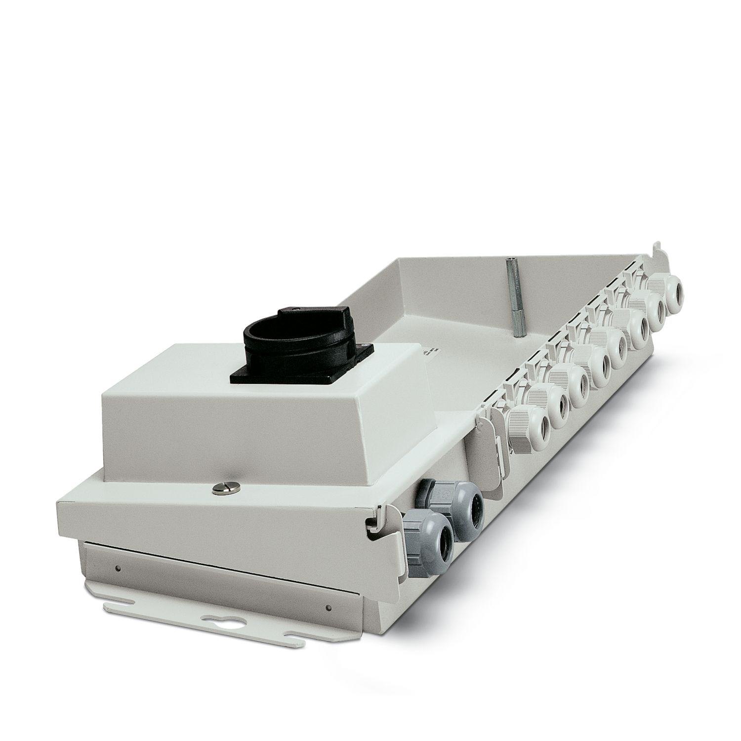
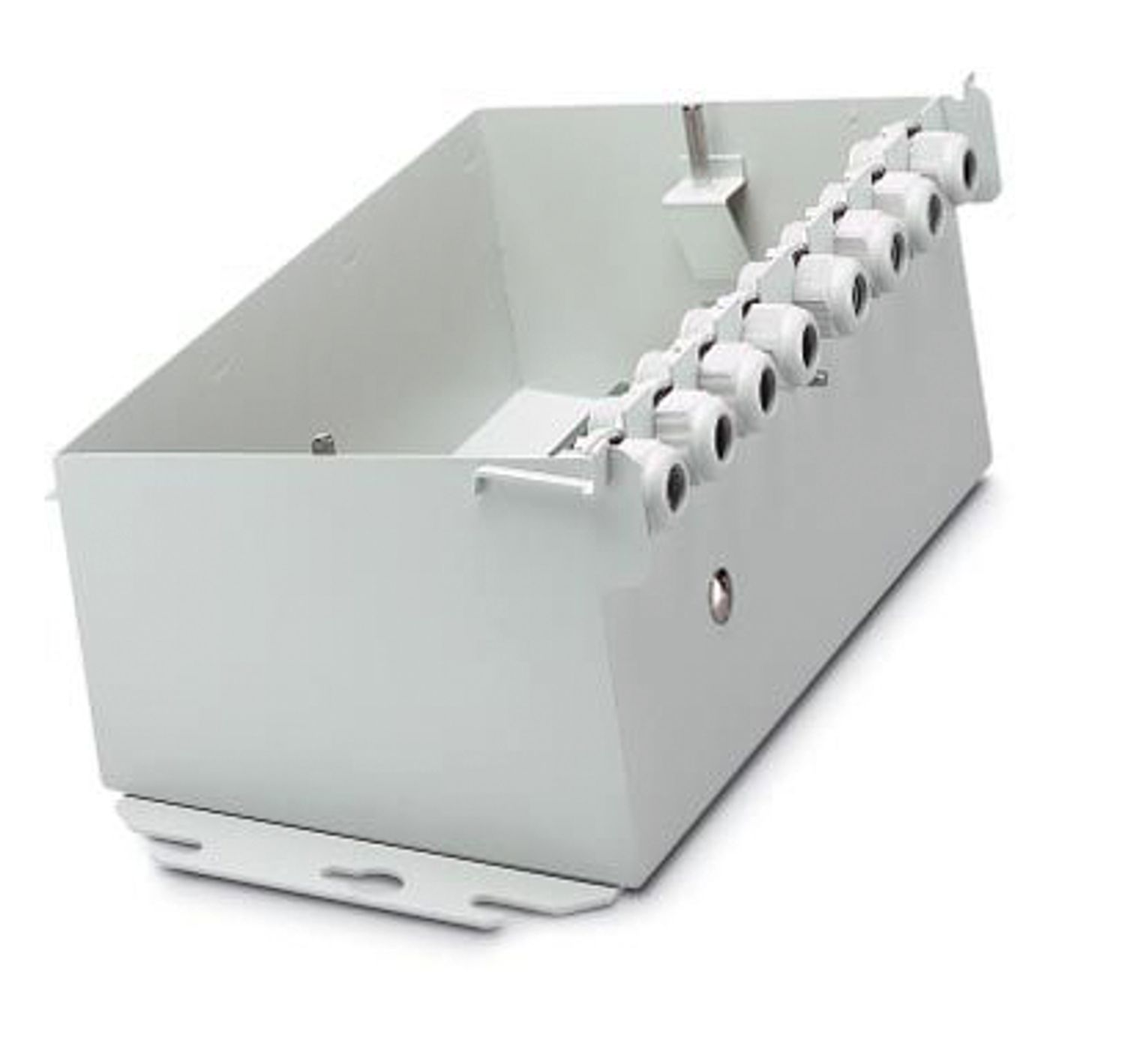
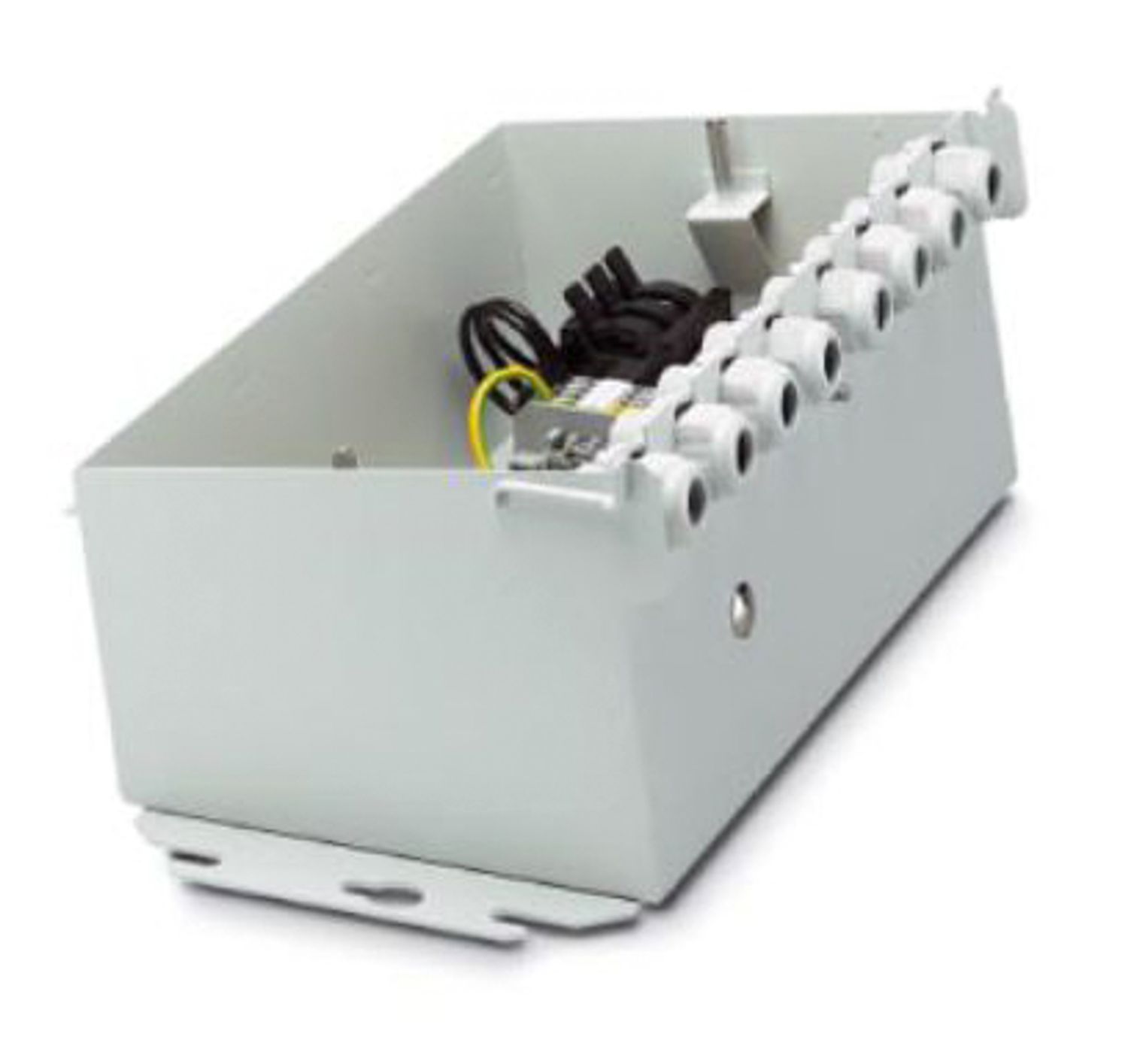
Motor starter
2734840
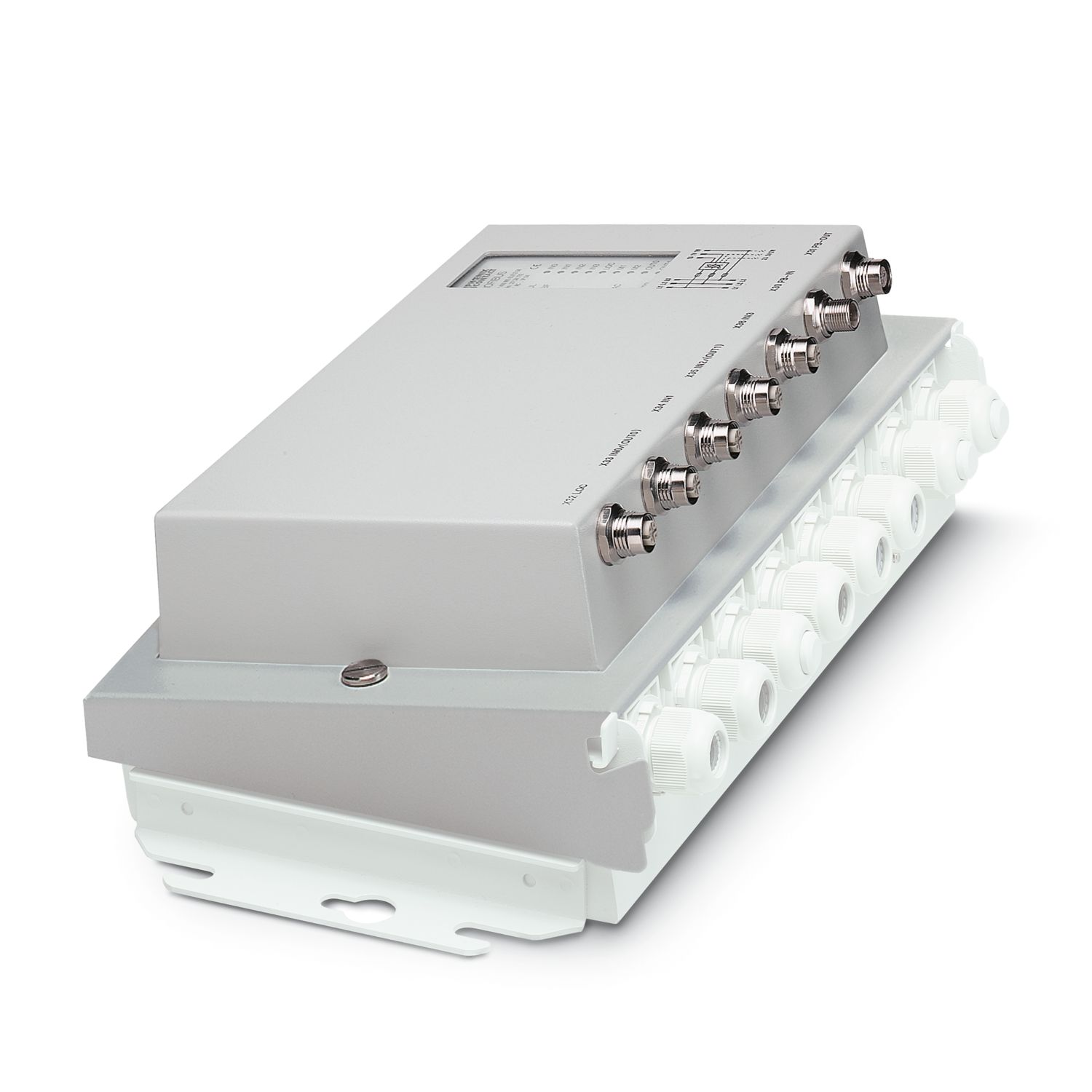
Module electronics, one-channel electronic reverse starter, PROFIBUS-DP connection, electronic motor monitoring can be used to switch on/off a three-phase asynchronous motor
Free download available.
Downloads
Product details
| Utilization restriction | |
| EMC note | EMC: class A product, see manufacturer's declaration in the download area |
| Type | Stand-alone |
| Diagnostics messages | Mains failure, phase failure Error message in the diagnostic code (bus) and display via the LED ERR on the module |
| Motor connector not plugged in, motor temperature exceeded, thermistor line short-circuited Error message in the diagnostic code (bus) and display via the LED ERR on the module | |
| Sensor supply failure Error message in the diagnostic code (bus) and display via the LED ERR on the module | |
| Overcurrent Error message in the diagnostic code (bus) and display via the LED ERR on the module | |
| Output stage cannot be controlled Error message in the diagnostic code (bus) and display via the LED ERR on the module | |
| Short-circuit or overload of the digital outputs Message in the diagnostic code | |
| Module error during self test Message to the master |
| Supply: Module electronics | |
| Connection method | POWER-COMBICON |
| Designation | Terminal strip X13 and X15 |
| Number of positions | 2 |
| Pg screw connection | Pg16R |
| Supply voltage | 24 V DC (US1) |
| Supply voltage range | 20 V DC ... 30 V DC (including ripple) |
| Supply current | typ. 0.17 A (at US1 = 24 V; plus current of digital inputs/outputs) |
| Ripple | Permissible ripple 3.6 Vpp within the permissible voltage range |
| Max. current carrying capacity | 16 A |
| Derating | from 30 °C 0.1A/K |
| Electrical isolation/isolation of the voltage ranges | |
| Test voltage: Remote bus / supply voltage US1 | 350 kV AC, 50 Hz, 1 min |
| Test voltage: Supply voltage US1 /400 V level | 1.2 kV AC, 50 Hz, 1 min |
| Test voltage: Supply voltage US1 / brake relay | 1.2 kV AC, 50 Hz, 1 min |
| Test voltage: Supply voltage US1 / thermistor inputs | 1.2 kV AC, 50 Hz, 1 min |
| Test voltage: Local bus/400 V level | 1.2 kV AC, 50 Hz, 1 min |
| Test voltage: Remote bus/brake relay | 1.2 kV AC, 50 Hz, 1 min |
| Test voltage: Remote bus/thermistor inputs | 1.2 kV AC, 50 Hz, 1 min |
| Digital: Digital inputs | |
| Number of inputs | 4 |
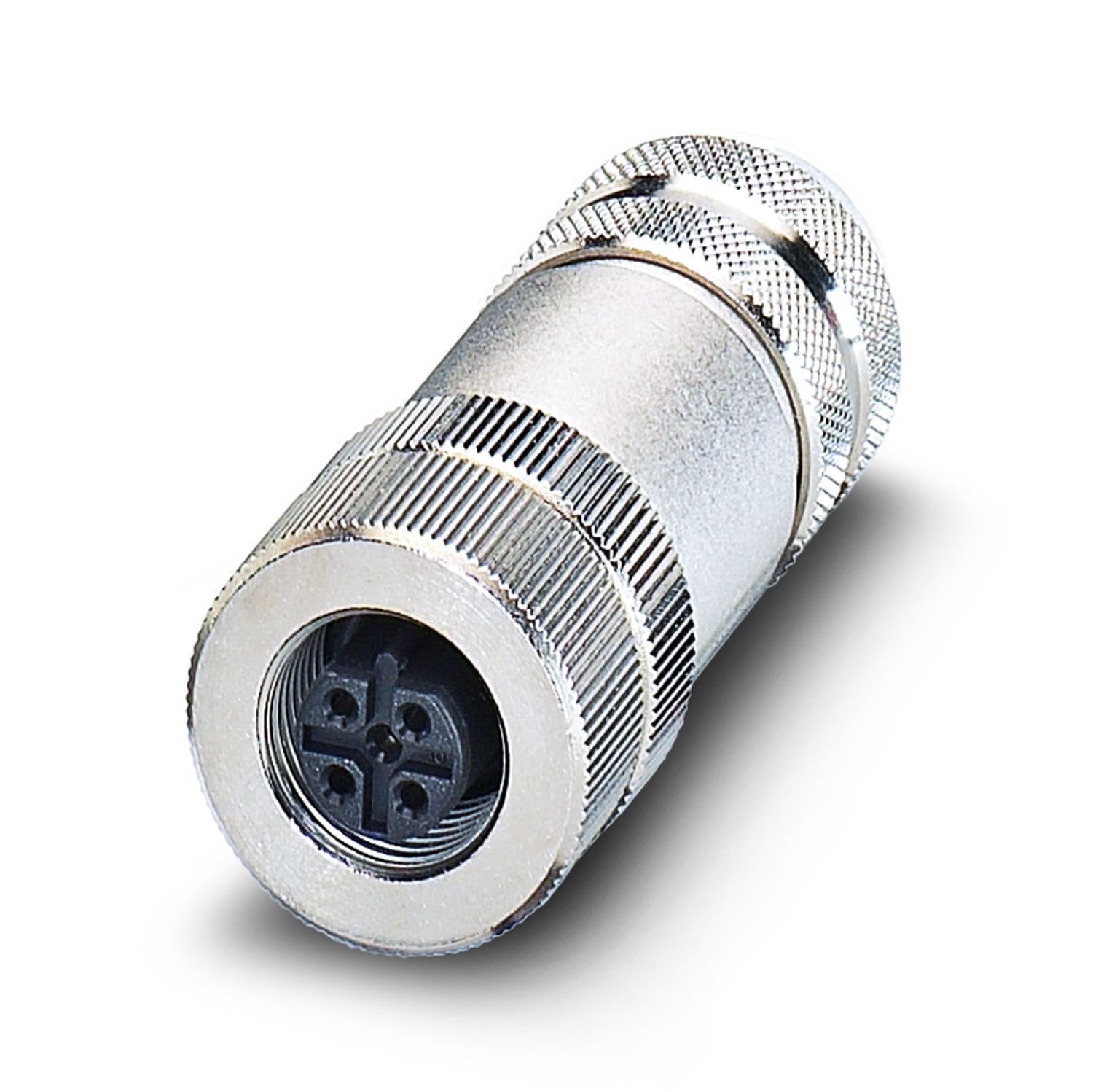
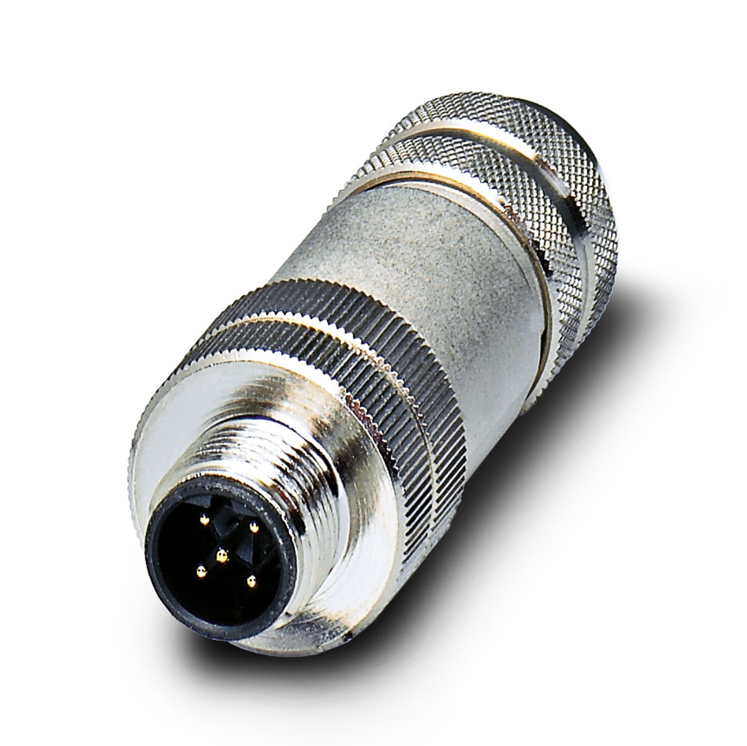
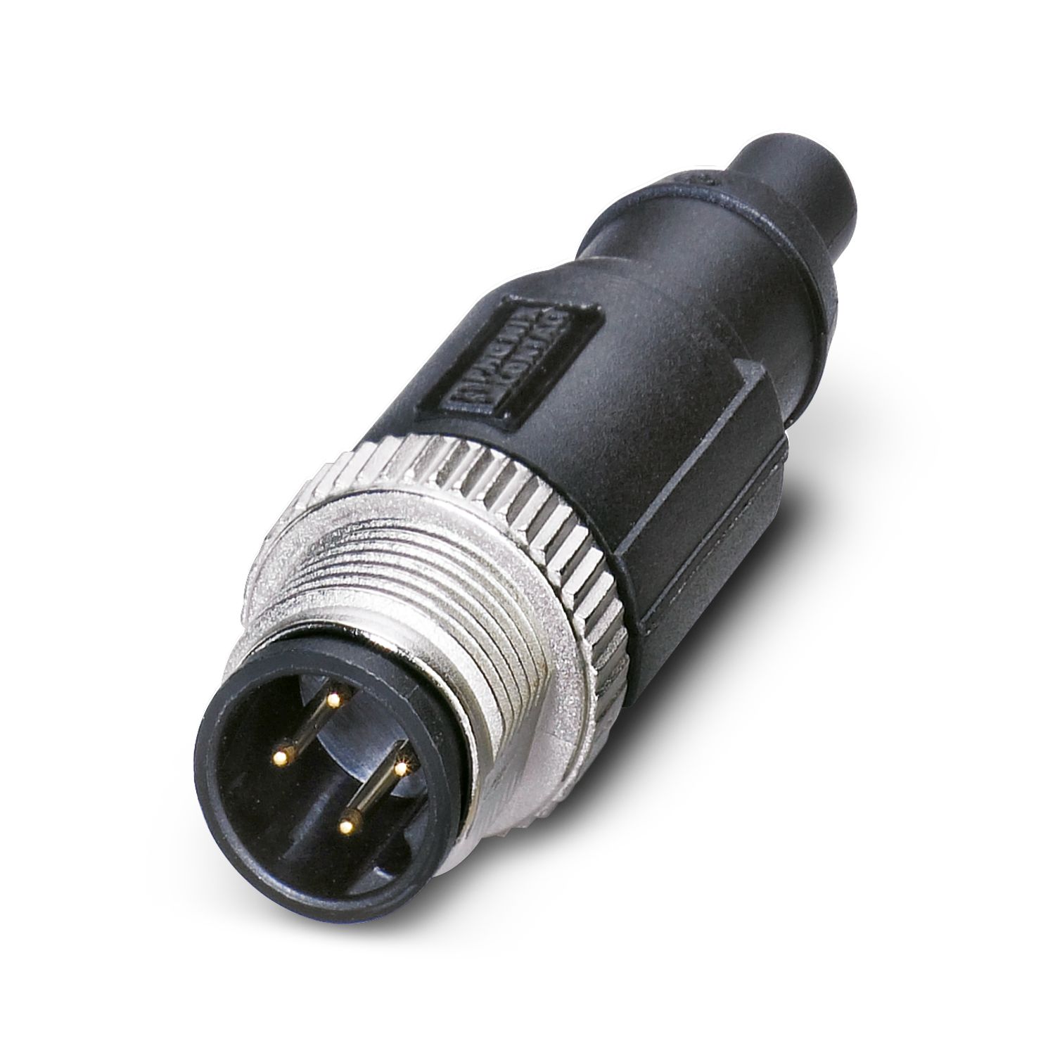
| Connection method | M12 connector, A-coded |
| Connection technology | 3-, 4-conductor |
| Number of positions | 5 |
| Input voltage | 24 V DC (US1) |
| Input voltage range "0" signal | -30 V ... 5 V (binary "0") |
| Input voltage range "1" signal | 13 V ... 30 V (binary "1") |
| Filter time | 3 ms |
| Typical input current per channel | approx. 5 mA (for US1 = 24 V) |
| PROFIBUS interface | |
| Connection method | M12 connector, B-coded |
| Designation connection point | M12 connector; X30 (IN) and X31 (OUT) |
| Number of positions | 5 |
| Permissible conductor cross section | 0.25 mm² ... 0.75 mm² (flexible) |
| Diagnostic messages | |
| Diagnostics | Mains failure, phase failure |
| Message | Error message in the diagnostic code (bus) and display via the LED ERR on the module |
| Diagnostic messages | |
| Diagnostics | Motor connector not plugged in, motor temperature exceeded, thermistor line short-circuited |
| Message | Error message in the diagnostic code (bus) and display via the LED ERR on the module |
| Diagnostic messages | |
| Diagnostics | Sensor supply failure |
| Message | Error message in the diagnostic code (bus) and display via the LED ERR on the module |
| Diagnostic messages | |
| Diagnostics | Overcurrent |
| Message | Error message in the diagnostic code (bus) and display via the LED ERR on the module |
| Diagnostic messages | |
| Diagnostics | Output stage cannot be controlled |
| Message | Error message in the diagnostic code (bus) and display via the LED ERR on the module |
| Diagnostic messages | |
| Diagnostics | Short-circuit or overload of the digital outputs |
| Message | Message in the diagnostic code |
| Diagnostic messages | |
| Diagnostics | Module error during self test |
| Message | Message to the master |
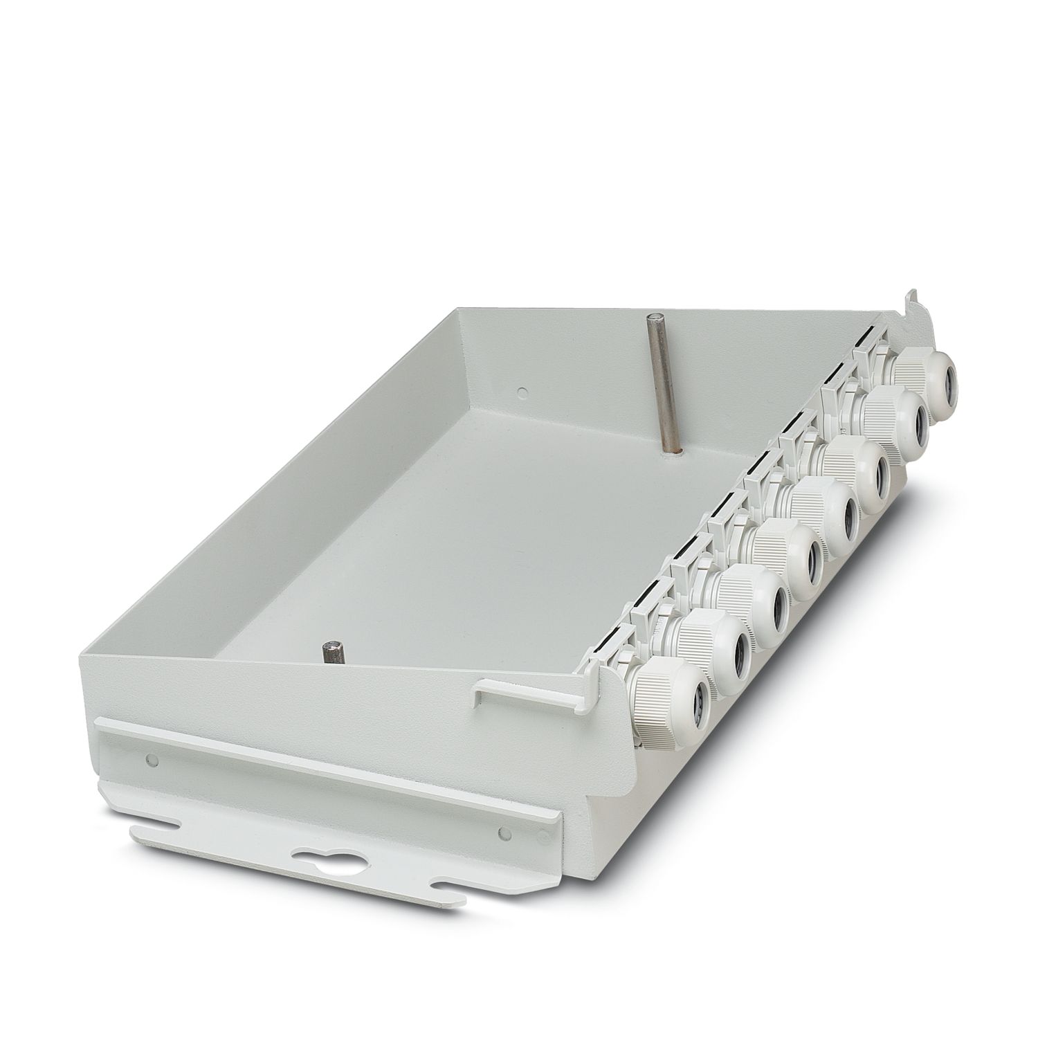
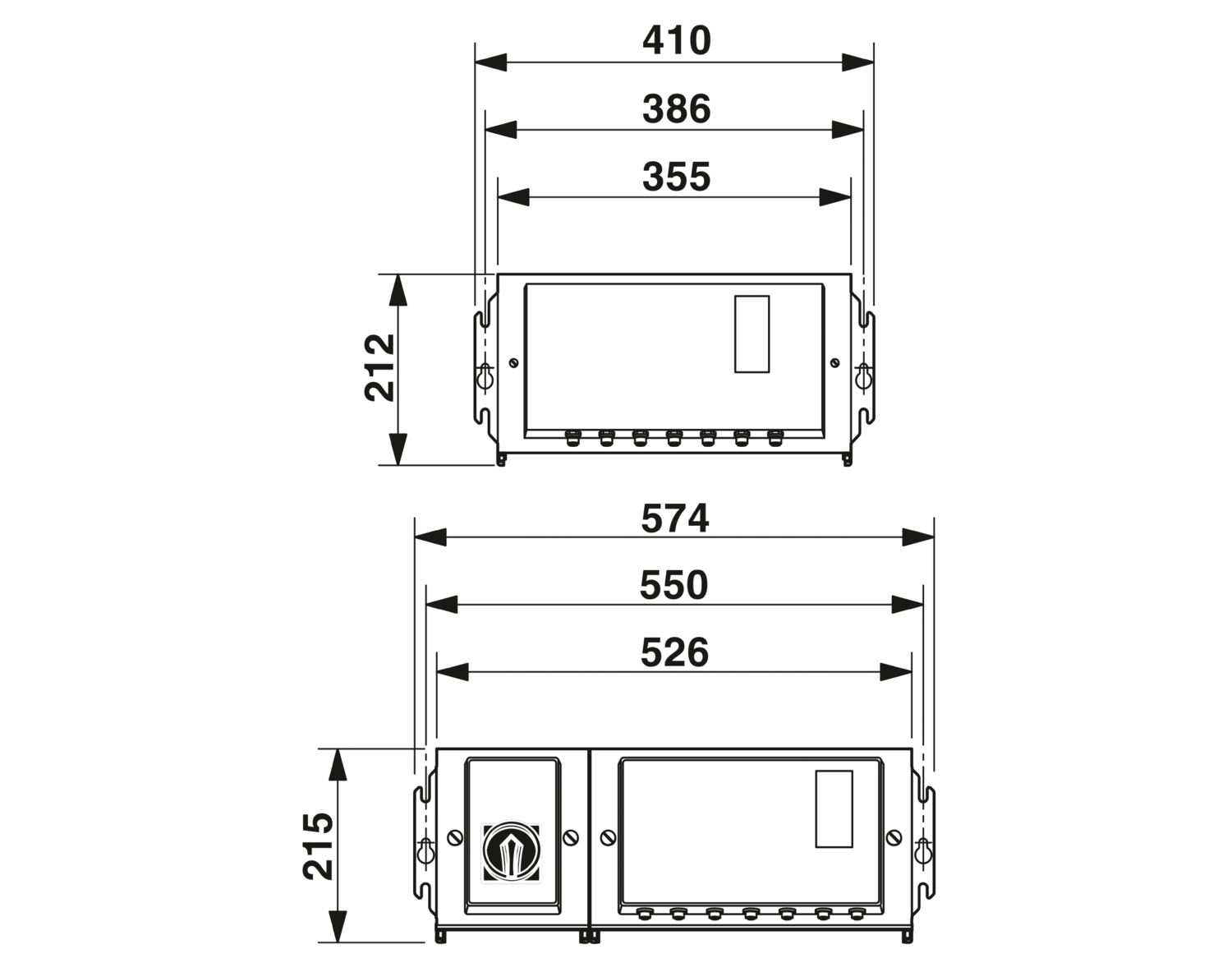
| Dimensional drawing |
|
| Width | 355 mm |
| Height | 180 mm |
| Depth | 100 mm |
| Drill hole spacing | 386 mm |
| Note on dimensions | Module electronics without lower part |
| Technical data | |
| Drill hole spacing | 386 mm |
| Ambient conditions | |
| Degree of protection | IP54 |
| Ambient temperature (operation) | -20 °C ... 55 °C (non-condensing) |
| Note | Notes on operation Line protection for the network supply line, max. 20 A. Observe derating of the POWER-COMBICON connector |
| Notes on operation Permitted network type TN network, TT network, IT network available on request | |
| Air pressure (operation) | 86 kPa ... 106 kPa (up to 2000 m above sea level) |
| Air pressure (storage/transport) | 86 kPa ... 106 kPa (up to 2000 m above sea level) |
| Ambient temperature (storage/transport) | -25 °C ... 75 °C |
| Permissible humidity (operation) | 4 % ... 100 % (non-condensing) |
| Permissible humidity (storage/transport) | 75 % (slight temporary condensation may sometimes appear on the housing) |
| Protection class | I (IEC 61140, EN 61140, VDE 0140-1) |
| Noise emission | Test of emitted interference, housing, in acc. with EN 50081-2:1993 EN 55011:1991 class A |
| Air clearances and creepage distances | |
| Air clearances and creepage distances | in accordance with EN 50178: 1998 |
| Mounting type | Panel mounting |