Surge protection in main power distributions Incorrectly installed surge protection poses a liability risk for planners and installers of switching devices. Connecting cables that are too long often lead to problems. Find out about correct installation and how to comply with the required cable lengths.

The correct location for the installation of surge protection
In large electrical systems, a separate transformer is often used for feed-in. A main power distribution with a miniature circuit breaker up to 7,000 A is installed on the low-voltage side. Surge protection must also be provided in these distributions in accordance with DIN VDE 0100-443.
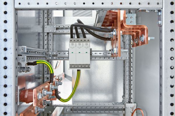
In power distributions with feed-in from below and a busbar system at the top or in the middle, the surge protection is usually installed above the miniature circuit breaker. There is a lot of room here in the incoming panel for the surge protective device and the necessary backup fuse.
The connecting cables to the surge protection become excessively long due to the large distances that have to be covered. This happens automatically with the paths from the busbars with L1, L2, and L3 that are installed at the top or in the middle and the rails for PE, N, and PEN located below. This is not just an aesthetic defect: Excessively long cables increase the effective voltage protection level in the switching device to a level that is no longer adequate.
Basic principles: Cable lengths and voltage protection level in detail

Voltage protection level in a switching device
The connection of surge protective devices, especially the cable length, has a significant influence on the effective voltage protection level in the switching device.
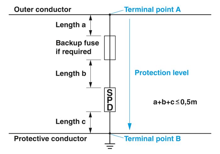
DIN VDE 0100-534 therefore stipulates a maximum cable length of 0.5 m between the phase and PE.

Overall effective voltage protection level in a switching device
On a 1 m long conductor installed in a straight line, a voltage drop of around 1 kV occurs in the event of a pulse current of 10 kA (10/350 µs).
ΔUL = (-) L ∙ di/dt
L = 1 µH/m
ΔUL = 1 µH ∙10 kA / 10 µs = 1 kV
This voltage drop must be taken into consideration when evaluating the overall effective voltage protection level.
The voltage drop over the connecting cables can quickly reach a value that is higher than the voltage protection level of the SPD. This is something that is often underestimated.
2. Evaluation of the effective voltage protection level
In large switching devices in particular, it is not always easy to keep cable lengths under 0.5 m.
Alternatively, you can also evaluate the effective voltage protection level in the system on an individual basis. This may sound complicated, but it doesn't have to be. This is actually the recommended action for larger switching devices.
In order to evaluate the effective voltage protection level, you must know and understand the protection objective. The protection objective is clearly defined: To ensure adequate protection of the equipment, voltage protection level Up between the active conductors and the protective conductor must under no circumstances exceed the necessary rated surge voltage Uw of the equipment to be protected.
This simply means that the voltage between the active conductors and the protective conductor must never be greater than the insulation resistance or electric strength of the equipment used. This also includes the control cabinet.
The electric strength of the equipment is defined by the rated surge voltage Uw. The devices are split into overvoltage categories.
Overvoltage categories for 230/400 V networks
Required rated surge voltage Uw between the active conductors and PE (ground).
| Rated surge voltage | Equipment | |
|---|---|---|
| Overvoltage category | ||
| IV | 6 kV | Equipment with very high rated surge voltage, e.g. electricity meters, ripple control receivers |
| III | 4 kV | Equipment with high rated surge voltage, e.g. distribution boards, switches, sockets |
| II | 2.5 kV | Equipment with normal rated surge voltage, e.g. household appliances, tools |
| I | 1.5 kV | Equipment with low rated surge voltage, e.g. sensitive electronic devices |
For the electrical system, you therefore only need to ensure that the effective voltage protection level remains below the rated surge voltage Uw.
And that is really not so difficult to do. In a larger main power distribution, all the equipment usually meets overvoltage category III, sometimes even category IV. This means that the equipment in 400 V networks is surge-proof up to 4 kV or 6 kV.
3. Voltage drop on connecting cables
On a 1 m long conductor installed in a straight line, a pulse surge current of 10 kA (10/350 µs) produces a voltage drop of around 1 kV. SPDs are not always connected with cables. Copper rails are typically installed in large switching devices. Due to their geometric shape, the rails have a lower inductance than cables.
The effect of the geometric shape on the inductance also applies to mounting plates. A mounting plate has a much lower inductance than a cable, resulting in a significantly lower voltage drop being produced by a pulse surge current. But take care: Do not disregard the voltage drop over the mounting plate and make sure you take into consideration the connections to the mounting plate.
Current change di/dt is decisive for the voltage drop over a connecting cable. For a pulse surge current of 10 kA (10/350 µs), the voltage drop on a straight and 1 m long conductor is around 1 kV. However, type 1 SPDs with a discharge capacity of 25 kA per position and up to 100 kA in total are often installed in large switching devices – i.e., ten times the 10 kA figure stated in normative documents. And a tenfold di/dt produces a tenfold voltage drop. This means that 1 kV rapidly becomes 10 kV.
Voltage drop depending on the geometry of the connection for various pulse surge currents
You can use the table to roughly determine the overall voltage protection level in an electrical system. The values specified are precise enough for the pragmatic dimensioning of connections.
| 10 kA | 25 kA | 40 kA | 75 kA | |
|---|---|---|---|---|
| Circular conductor, any cross section | 1.0 | 2.5 | 4.0 | 7.5 |
| 30 x 2 mm copper flat-ribbon cable | 0.9 | 2.3 | 3.6 | 6.8 |
| 30 mm copper rail | 0.9 | 2.3 | 3.6 | 6.8 |
| 60 mm copper rail | 0.8 | 2.0 | 3.2 | 6.0 |
| 100 mm copper rail | 0.7 | 1.8 | 2.8 | 5.3 |
| 120 mm copper rail | 0.7 | 1.8 | 2.8 | 5.3 |
| Sheet steel | 0.4 | 1.0 | 1.6 | 3.0 |
| VA stainless steel sheet | 0.3 | 0.8 | 1.2 | 2.3 |

Voltage protection level in a switching device with backup fuse
Effect of a backup fuse on the voltage protection level
To calculate the overall effective voltage protection level in the electrical system, the partial voltages of all connecting parts between the line conductor (terminal point A) and the protective conductor (terminal point B) must be added to the actual voltage protection level of the SPD. The cable paths to the backup fuse must also be taken into consideration here.
The cable paths from and to the backup fuse must not be underestimated. In addition, a backup fuse for a type 1 SPD also has a correspondingly high rating. In order to safely carry the nominal surge current of 25 kA per position without tripping, an NH fuse must have a rating of 315 A. This is only possible using at least NH2 fuses, which are rather large in size and take up additional space in the control cabinet.
Calculation of the effective voltage protection level in the electrical system using three examples
As described, the partial voltages of all connecting parts between the line conductor (terminal point A) and the protective conductor (terminal point B) must be added to the actual voltage protection level of the surge protective device (SPD).
We have performed this calculation for the following three examples.
The voltage drop over the corresponding cables has been taken from the table for the “Voltage drop depending on the geometry”.

FLT-SEC-HYBRID above the circuit breaker
1. Installation: Above the circuit breaker
Installation is located above the circuit breaker on a grounded mounting plate, which is a considerable distance away from the PEN rail below it.
Note:
Install a direct cable connection from the protective device to the PEN rail, parallel to the connection via the mounting plate. This connection does not increase the voltage protection level of the SPD combination, but is prescribed by DIN VDE 0100-534.
Effective voltage protection level, example 1
With a voltage protection level of 8.2 kV, protection in accordance with overvoltage category IV for switching devices in 230/400 V networks cannot be maintained.
| Length in cm | Partial current in kA | Voltage drop in kV | |
|---|---|---|---|
| PEN connection from SPD to mounting plate | 15 | 75 | 1.1 |
| PEN connection via mounting plate | 115 | 75 | 3.5 |
| PEN connection from mounting plate to PEN rail | 15 | 75 | 1.1 |
| L1-L3 connection | 40 | 25 | 1.0 |
| SPD (voltage protection level) | - | 25 | 1.5 |
| Overall voltage protection level | 8.2 |

FLT-SEC-HYBRID in the main distribution
2. Installation: Below the circuit breaker
The SPD is installed below the circuit breaker.
For this installation variant, the distance to the protective conductor is relatively short.
Effective voltage protection level, example 2
With a voltage protection level of 4 kV, protection in accordance with overvoltage category III for switching devices in 230/400 V networks can be maintained.
| Length in cm | Partial current in kA | Voltage drop in kV | |
|---|---|---|---|
| PEN connection from SPD to PEN rail | 20 | 75 | 1.5 |
| L1-L3 connection | 40 | 25 | 1.0 |
| SPD (voltage protection level) | - | 25 | 1.5 |
| Overall voltage protection level | 4.0 |

Calculation of the voltage protection level
3. Installation: Below the circuit breaker
The SPD is installed below the circuit breaker with optimized PEN connection.
Examples 1 and 2 clearly show that when optimizing the voltage protection level, the focus should be on the connection from the SPD to the PEN rail. The shorter this connection is, the better the voltage protection level. In examples 1 and 2, the influence of the PEN connection is three times higher than the connections to active conductors L1, L2, and L3.
Instead of using one cable to implement the connection to the PEN rail, another option is to use a separate cable for each position, i.e., three individual cables. In this case, the partial current flowing through the cables is just 25 kA and not 75 kA. Accordingly, the voltage drop is then also just a third.
Effective voltage protection level, example 3
With a voltage protection level of 2.5 kV, protection in accordance with overvoltage category II for switching devices in 230/400 V networks can be maintained.
| Length in cm | Partial current in kA | Voltage drop in kV | |
|---|---|---|---|
| PEN connection from SPD to PEN rail | 10 | 25 | 0.25 |
| L1-L3 connection | 10 | 25 | 0.75 |
| SPD (voltage protection level) | - | 25 | 1.5 |
| Overall voltage protection level | 2.5 |
Our solution: FLT-SEC-Hybrid
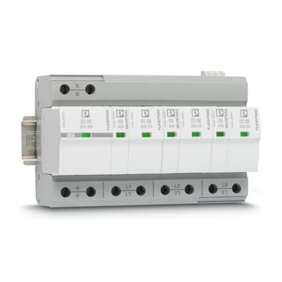
The type 1 surge protective device with integrated FLT-SEC-Hybrid fuse is a solution that saves space, money, and valuable cable length.
A separate backup fuse is not required, which opens up new possibilities for the installation location of the surge protective device (SPD). The SPD operates discreetly in the background and ensures safety.
FLT-SEC-H combines a spark gap without line follow current with a surge-proof fuse and can be used without a separate backup fuse. The short-circuit power of up to 100 kA means that it is also suitable for large power distributions.
The video highlights the challenge of correctly installing surge protection and backup fuses. Our colleague explains how proper installation must be carried out. The video also shows how much space is saved in the control cabinet with our solution, the FLT-SEC-Hybrid.
Advantages of installation with FLT-SEC-H Compared to an installation with separate backup fuse
- Up to 80% more space in the control cabinet
- Shorter cable paths, for a low voltage protection level
- Safe system testing with pluggable protection modules


