Spark gaps
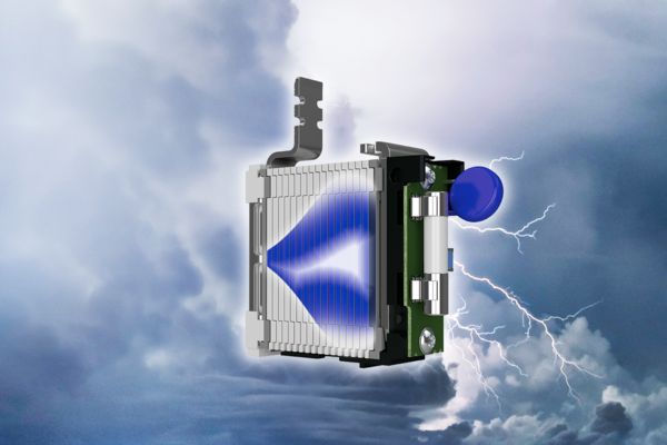
Spark gaps are the heart of our type 1 lightning arresters. They make it possible to dissipate the high energies and surge currents generated by lightning strikes to ground in a fraction of a second. To provide you with the optimum protection for your systems, our development team is constantly working on new, even better solutions.
Robustness and endurance in perfect balance
Discover the technology of our new triggered multi-carbon spark gap in detail here and take a look at the history of our spark gaps.
Particularly high performance on an overall width of just 1 HP per position
Energy absorption more than twice as high as required by standards
Fast response time and low residual voltage, very good protection of the electrical system
No tripping of the backup fuse, neither with small nor large overvoltage events
The development of the triggered multi-carbon spark gap made my engineering heart beat faster. I am pleased that we have been able to set a new milestone for your system availability with this technology.
Dr. Gernot Finis, Vice President System Protection Technologies, Phoenix Contact GmbH & Co. KG
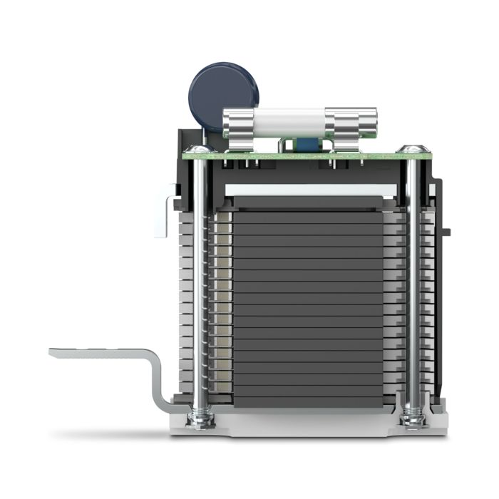
Structure of the new spark gap with triggered multi-carbon technology
Triggered multi-carbon spark gap technology
Robustness and endurance in perfect balance
The new triggered multi-carbon spark gap significantly exceeds current market standards. With this new technology, all lightning currents are managed equally without affecting neighboring devices. Even the high energies of several pulse trains in a short time are safely dissipated. The triggered multi-carbon spark gap is the first to provide reliable and durable protection against lightning currents and surges of any kind.
What makes triggered multi-carbon spark gap technology so special?
The new multi-carbon spark gap uses particularly robust materials. The energy to be dissipated is distributed ideally over the entire installation space. As a result, it shows no signs of aging, even after multiple loads that exceed the normative requirements.
The FLT-MB-T1... is the first lightning current arrester with the triggered multi-carbon spark gap. This technology enables an overall width of just 72 mm. This makes the protective device just half the size of the comparable FLT-SEC-P-T1... with similar performance values. This enables a space-saving and more flexible installation.
Structures in exposed locations, such as telecommunications or wind turbine generators, are struck by lightning significantly more often than other buildings. Over the operating period, this leads to a significantly higher energy load. The lightning arresters with the new multi-carbon technology can dissipate more than twice as much energy as required by IEC 61643-11 and thus meet corresponding guidelines.
Short-circuit currents may occur within the system after a surge voltage event has been discharged. The new multi-carbon technology suppresses these short-circuit currents very quickly and efficiently, so that even small fuses do not blow and your system always remains available.
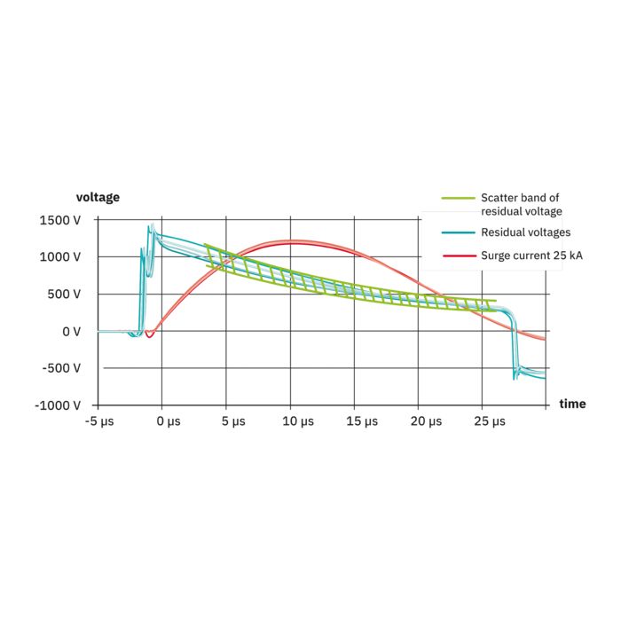
The spark gap has a very fast response behavior and a low residual voltage curve. Compared with varistor-based (MOV) lightning current arresters, the load on the end device is significantly reduced, which greatly improves the protective effect for the whole of the system.
Animation of the new spark gap
Learn more about our new triggered multi-carbon spark gaps in this animation. What is the difference in the way it works? What are the basic advantages? The animation gives a clear and concise overview of our new spark gap technology.
Residual voltage curves of different technologies in lightning current arresters
Surge voltage pulse
A surge voltage pulse is used to test the insulation strength of an end device. This example shows the pulse in the case of a device of overvoltage category II.
Multi-carbon spark gap triggered by residual voltage curve
The curve shows the voltage to which a lightning current arrester with triggered multi-carbon spark gap limits the overvoltage. The residual voltage is already below that of the varistor after a few µs and always below the insulation strength of the end device (surge voltage pulse + operating voltage).
Varistor residual voltage curve
The curve shows the voltage to which a varistor-based lightning current arrester limits the overvoltage. The residual voltage does not return to the operating voltage until after the event has ended.
Operating voltage
The gray area indicates the amplitude of the operating voltage in a 230 V supply network.
The evolution of our spark gaps
FLT-MB... type 1+2+3 combined lightning current and surge arrester with triggered multi-carbon spark gap
Type 1+2+3 combined lightning current and surge arrester
With triggered multi-carbon spark gap
The lightning current arresters with triggered multi-carbon spark gap were developed as combined lightning current and surge arresters. In addition to the normative requirements for type 1 lightning current arresters, they also meet the requirements for type 2 and type 3 surge protection devices.
The low voltage protection level of 1.5 kV enables universal use, even as device protection.