Basic principles of shielding Do you need help with the professional shielding of your systems? We will be happy to assist you with the planning and selection of the right components.


Magnetic and electrical fields
How is electromagnetic field interference created?
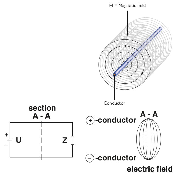
A consumer (Z) is supplied by a voltage source (U) via cables. Voltage differences arise between the positive and negative conductors, which generates an electrical field between the conductors. A magnetic field (H) is generated around a live conductor. Due to it being current-dependent, this magnetic field is subject to temporal fluctuations. Because a time-constant current is only present in a very small number of applications, this leads to irregular, alternating magnetic fields. The fields become electromagnetic signals, a type of “mini-transmitter”, and receivers at the same time. Each conductor is therefore capable of negatively influencing the function of other electrical and electronic devices. To prevent such influences from having a noticeable effect on your devices and system, you require professional cable and conductor shielding.

Galvanic interference
Galvanic interference
Galvanic interference occurs when two circuits use a common conductive part. This is often a common reference or return conductor. Current or voltage fluctuations in the first circuit (e.g., switching operations) influence the second circuit. However, incorrect grounding of shielded MCR and data transmission cables can also result in galvanic interference.
Countermeasures:
- Ensure that the common conductive part is as low impedance and low inductance as possible (use a sufficiently large conductor cross-section)
- Separate the circuits as much as possible
- Keep common supply lines as short as possible
- Position branching points as close to the current source as possible

Capacitive interference
Capacitive interference
The disturbance variable of capacitive interference is the electrical voltage. Capacitive interference is caused by alternating electrical fields of a system that act as disrupters. A typical example of capacitive interference is when two cables laid in parallel over a longer path behave as two opposing capacitor plates and, in this role, act as a short circuit for high-frequency signals.
Countermeasures:
- Avoid parallel installation wherever possible or keep it as short as possible
- The distance between the disruptor and the disrupted cable must be as great as possible (minimum distance of 60 – 100 cm)
- Use shielded data transmission and MCR cables (shielding connected at one end)
- Use twisted pairs of cables

Inductive interference
Inductive interference
Inductive interference is caused by an alternating magnetic field. A magnetic field is generated around a live conductor, which also penetrates adjacent conductors. A change in current also causes a change in the magnetic field, which then induces a voltage in the adjacent conductors.
Example: When two 100 m cables are laid parallel to each other 30 cm apart and the current going through the disruptive conductor is 100 A (50 Hz), voltage of approx. 0.3 mV is induced in the disrupted conductor. For the same arrangement but with a 1 kA current change in 100 μs, a voltage of approx. 90 mV is induced. The faster and greater the change in current, the higher the induced voltage.
Countermeasures:
- Distance of at least 1 m between power cables and data transmission and MCR cables
- Parallel paths should be as short as possible
- Using twisted cables can reduce inductive influence by a factor of around 20
- Use cables that are shielded at both ends (shielding)
Twisted cables?
Using twisted cables reduces inductive interference because the direction of induction is constantly reversed in relation to the interference field due to the twisting of the wires. To avoid couplings, adjacent pairs in a data transmission- or MCR cable are arranged with different twist pitches. Twist pitches from 30 to 50 mm are typically used. In the case of power cables, the twist pitch is between 200 and 900 mm depending on the conductor cross-section.

Wave interference
Wave interference
In the case of wave interference, conducted waves or pulses occur which overlap onto adjacent data transmission and MCR cables. Wave interference also occurs when one line circuit overlaps with another within a cable. In the case of galvanic, capacitive, and inductive interference, the runtime of the electrical signals on the disruptive cable and the disrupted cable is not taken into consideration. In exceptional cases, the wavelength of the interference frequency can come close to the size of the cable lengths. When this is the case, the effect must also be taken into consideration here.
Countermeasures:
- Use cables with shielded pairs and overall shielding
- Avoid mismatching in the overall cable run
- Do not transmit signals with a very high level over the same cable as signals with a very low level
- Use cables with very low reflection, low attenuation, and low capacitance

Radiation interference
Radiation interference
Non-conductive electromagnetic waves from a disruptor can also affect systems and cables. The disruptor is free wave H0, E0. In the near field, the electrical or magnetic field can prevail depending on the type of interference. High currents predominantly generate a magnetic field, while high voltages predominantly generate an electrical field. High-frequency interference energy spreads via cables that are connected to the source of interference and enable direct radiation (>30 MHz). In addition, nearby powerful transmission stations can cause high field strengths at the location of the cable system and have a disruptive effect on cables. In industrial plants, by far the greatest interference is caused when switching off inductive loads. This process generates large, high-frequency voltage transients called “bursts.“ Bursts have a frequency spectrum of up to 100 MHz.
Countermeasures:
- Use shielding with high absorptive and reflective capacity in the far and near field (copper or aluminum). Conductive and ideally fully enclosed shielding with low coupling resistance and favorable shield attenuation values should be used here. (Shielding)
- In the case of a predominantly magnetic near field, especially at low frequencies, mu-metal or an amorphous metal should be used to provide additional shielding.

Shield connections as a protective measure
Shielding as a suitable protective measure
The type of shield connection used depends mainly on the type of interference to be expected. For the suppression of electrical fields, it is necessary to ground (1) the shield at one end. Interferences caused by an alternating magnetic field, however, are only suppressed when shielding is implemented at both ends. Connecting the shield at both ends (2), however, creates a ground loop, which has well-known disadvantages. Galvanic interferences along the reference potential in particular influence the useful signal and reduce the shielding effect. Here, the use of tri-axial cables (4), in which the inner shield is connected at one end and the outer shield at both ends, is a solution. To reduce galvanic interference when the cable shield is connected at both ends, one end is often also connected to the reference potential via a capacitor (3). This interrupts the ground loop, at least for direct and low-frequency currents.

Effectiveness of shielding measures
Shielding effectiveness
The following example demonstrates the effectiveness of measures intended to protect against interference. The illustrated arrangement is exposed to an alternating magnetic field with 50 kHz over a length of 2 m. The interference voltage measured at the output is specified in relation to the interference voltage when the conductor shield is not connected (1) 0 dB. When the shielding is connected at one end (2), there is no improvement since it is not effective against magnetic interference. When a shield is connected at both ends, as illustrated in Figure 3, the interference field is attenuated by approx. 25 dB. Even without shielding, the twisted cable (20 twists per meter) is less susceptible to interference (approx. 10 dB) in arrangement (4). This is achieved by the compensating effect of the conductor loops. When the shield is then connected at one end (5) there is once again no improvement. It is only when the shield is connected at both ends in arrangement (6) that the attenuation improves to approx. 30 dB.
