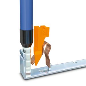
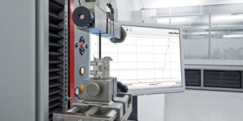
Material tests Material tests are used to check the terminal blocks for material changes. The focus of the material tests is on longer load tests in the form of constantly higher temperatures, a comparative tracking index due to moisture and dirt, and the simulated aging of materials.
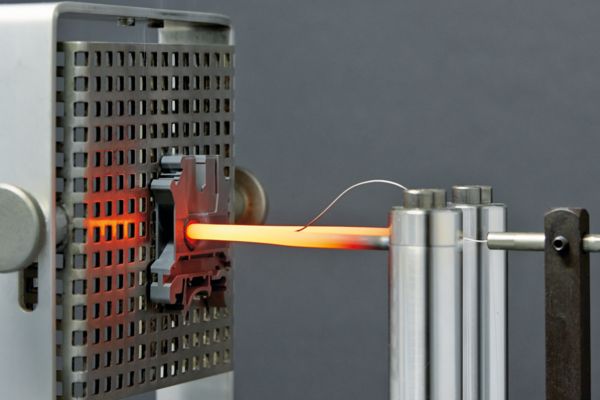
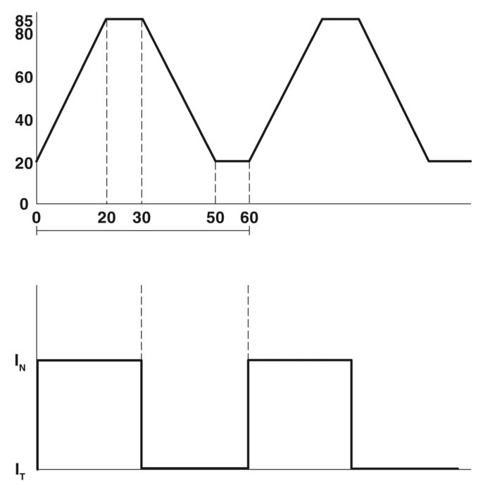
Diagram of current and temperature in relation to time
Aging test (IEC 60947-7-1/-2)
From the point of view of long lifecycles of the terminal blocks, the aging behavior also plays an important role. In this test, the contact quality is verified by means of simulated aging. To simulate several years of use, five terminal blocks are mounted horizontally on a rail and connected in series using conductors with the rated cross-section. Conductors with a minimum length of 300 mm are connected and the voltage drop is measured at every terminal block. The minimum temperature in the climate cabinet is set to +20°C. In contrast, the upper temperature is set so that the maximum permissible operating temperature (max. +120 C) of the test object is reached during the 10-minute pause phase. During the heating phase and the pause phase at the maximum temperature, the rated current flows. As a result, the maximum permissible operating temperature of the test object (maximum +130°C) is reached. This is followed by the cooling phase. The voltage drop is always measured after 24 cycles in the cooled-down state (approximately +20°C). The test consists of a total of 192 cycles. The voltage drop must not exceed 3.2 mV initially. During or after testing, it must not exceed 4.8 mV or 1.5 times the value measured after the 24th cycle. Terminal blocks from Phoenix Contact are designed for extreme durability even under difficult temperature conditions. Plastic as well as metal parts provide sufficient safety reserves.

1: Radiant heater, 2: Flame, 3: Plastic sample
Fire protection (EN 45545-2)
EN 45545-2 has replaced the national fire protection standards for rail vehicles since March 2013. The current version of EN 45545-:2013+A1:2015 presents the demands placed on the fire behavior of materials and components. To qualify plastics for certain operating and design classes of rail vehicles, the standard describes testing methods for determining hazard levels (HL). In this case, HL3 corresponds to the highest requirements. The following tests are performed in order to qualify the plastics for electrical engineering applications:
- Oxygen index according to DIN EN ISO 4589-2
- Development of smoke gas in accordance with EN ISO 5659-2 (25 kW/m²)
- Toxicity of smoke gas NF X70-100-2 (600°C)
- Vertical small flames test in accordance with EN 60695-11-10
The unreinforced polyamides used in Phoenix Contact terminal blocks with flammability rating UL 94 V0 meet the highest demands. They meet the most stringent requirement of flammability rating HL3 in accordance with the tests described in the requirement sets R22, R23, R24, and R26.

Test setup according to UL 94
Inflammability classification (UL 94)
The UL 94 standard describes inflammability tests that have gained particular importance in the field of electrical engineering. Fire behavior is the main focus. Items are classified in accordance with either UL 94 HB (Horizontal Burn) or UL 94 V (Vertical Burn). The test setup is such that the UL-94-V0/1/2 classifications are stricter than the UL-94HB classification.
UL 94 V0/1/2
After conditioning, the test bar is vertically clamped and flame-treated several times for 10 seconds at a time. Between the flame treatments, the time until the test bar is extinguished is measured. Afterwards, the afterburning times and the drip behavior are evaluated. The plastic used for Phoenix Contact terminal blocks satisfies the higher-grade criteria for classification as a V0 material.
Test values for inflammability classification
Test values for material classifications V0, V1 and V2.
|
Material classification
V0 |
Material classification
V1 |
Material classification
V2 |
|
|---|---|---|---|
| Criteria | |||
| Afterburning time with flame of a single test object (t1 and t2) | ≤10 s | ≤30 s | ≤30 s |
| Total afterburning time with flame of a set of test objects after respective conditioning (tf) | ≤50 s | ≤250 s | ≤250 s |
| Afterburning time with flame plus afterglow time of each individual test object after the second flame (t2 plus t3) | ≤30 s | ≤60 s | ≤60 s |
| Afterburn and/or afterglow of a single test object to the holder is allowed to occur? | No | No | No |
| Ignition of the cotton pad by burning particles or drops is allowed to occur? | No | No | Yes |

Polyamide plastic granulate PA 6.6, frequently used for terminal blocks
Calorific value (DIN 51900-2/ASTME 1354)
The fire load is defined as the amount of energy released over a particular area during burning. The fire load value is usually expressed in MJ/m². The value is calculated based on the calorific value of a substance and the combustion factor (DIN 18230-1). The higher the calorific value and the presence of a substance, the greater the amount of energy released during burning. It follows that the possible fire load value is also higher. This affects all installed components in the application to be considered. The calorific values of polyamides such as PA 6.6 are relatively high (for comparison: the calorific value of fuel oil is approx. 44 MJ/kg). For this reason, the calorific values of terminal blocks are also increasingly included in the fire load determination. Calorific values of the plastics used by Phoenix Contact in accordance with DIN 51900-2 and ASTM E 1354 can be found in the following table. To calculate the fire load of individual components, the calorific value of each polyamide must be multiplied by the weight of the part and the number of items installed. Documentation of the heat emission takes place in the cone calorimeter in accordance with ISO 5660-1 for the plastic materials.
Heating values of commonly used plastic types
Overview of the average calorific value types for PA6.6 V0 and V2 in accordance with DIN 51900-2 and ASTM E 1354.
| DIN 51900-2 | ASTM E 1354: | |
|---|---|---|
| Plastic type | ||
| Polyamide 6.6 V0 | Approx. 30 MJ/kg | Approx. 22 MJ/kg |
| Polyamide 6.6 V2 | Approx. 32 MJ/kg | Approx. 24 MJ/kg |
| For comparison: heating oil | - | Approx. 44 MJ/kg |

Setup of a glow-wire test
Glow-wire test (IEC 60695-2-11)
In the event of overload, conductive metal parts of the terminal block or connected conductors can heat up considerably. This additional heat also affects the plastic housing. To simulate this source of danger for electrical engineering components, a glow wire is heated to a particular temperature (+550°C, +650°C, +750°C, +850°C, or +960°C). As shown in the figure, the wire is then pressed onto the thinnest point of the test object housing at a right angle with a force of 1 N.
The test is considered passed for the following results:
- When no flame or glowing process occurs during the test
- When the flames or glowing processes are extinguished within 30 seconds of the glow wire being removed
- When the tracing paper beneath the glow wire does not ignite due to any drops of burning substances falling down
The polyamides used by Phoenix Contact as housing materials all fulfill the requirement of the glow-wire test at +960°C (highest temperature level).
Halogen-free flame protection (DIN EN ISO 1043-4)
Inflammability is a huge risk when using plastics in connection technology. Particularly in the event of an electrical fault, there is the possibility that the inflammation temperatures of polyamide (PA 6 and PA 6.6) or polycarbonate (PC) will be exceeded. To prevent fire, the plastic must be flame-retardant and self-extinguishing. This can be achieved through three types of flame protection agents:
- Organic halogen compounds (e.g. fluorine, chlorine bromine, or iodine)
- Inorganic substances (e.g. aluminum, magnesium oxyhydrate, or zinc borate)
- Phosphorus or melamine-based flame protection
One property of halogen compounds is the ability to stop chain reactions in plastic. Without this property, a possible combustion process would not be stopped. Unfortunately, however, this substance is highly toxic and generates extremely poisonous vapors in the event of a fire. Therefore, they are also prohibited for many applications in the context of the RoHS directive. When exposed to heat, inorganic substances tend to have the effect of splitting off water and thus cooling the surface. Thus, the ignition temperature in the fire area is not reached and the fire process is slowed down. However, for effective fire protection, high levels must be mixed into the plastic. This circumstance leads to a deterioration of the mechanical properties. This leaves the phosphorus or melamine-containing flame retardant additives. These additives can counteract the fire by charring the surface or by creating a kind of foaming. This slows down the supply of oxygen to the direct source of the fire. A striking effect is possible even with relatively small amounts in the polyamide. Terminal blocks from the CLIPLINE complete system made of polyamide are manufactured with fire protection classification UL 94 V0. Melamine cyanurates are used as flame protection agents. As such, all Phoenix Contact terminal blocks are entirely free of halogens based on the flame protection systems used.

Diagram for extrapolating the TI and HCI value
Insulating material properties TI (IEC 60216-1)
In the associated test, an increased thermal load on the terminal block is simulated over a longer period of time. For this purpose, the behavior of plastics at constantly higher temperatures is considered with respect to the tensile strength (mechanical properties). The standard requires at least three, but preferably four, different temperature measurement series to be performed on a test piece. The tensile strength is measured over 500 h to 5,000 hours depending on the specification and the result is extrapolated to 10,000 hours (HCI) and 20,000 h (TI). After these 20,000 hours, you can determine the temperature at which the tensile strength decreased by half. IEC 60216 specifies the TI as a temperature index that permits conclusions to be made about the mechanical service life of plastics under thermal loads.
TI values according to UL 94 V2: +105°C
TI values according to UL 94 V0: +125°C
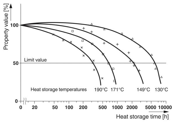
Diagram for determining the temperature
Insulation material properties RTI (UL 746 B)
In the following tests, an increased thermal load on the terminal block is simulated over a longer period of time. To do so, multiple different test temperatures are evaluated in reference to 50% insulation strength loss (I. quadrant: hot, warm, cold). These different storage times until the 50% drop occurred are then plotted against the corresponding storage temperatures (IV. quadrant). This creates a time temperature curve (III. quadrant). An insulation resistance-based temperature value (RTI) can then be derived from this curve. This value then corresponds to a 20,000-h time span with 50% property loss. UL 746 B provides a temperature index for the various polyamide combustibility classes. This index can be used to make a statement about the electrical service life.
UL 746 B (RTI value)
The RTI indicates the highest operating temperature before an electrical disruptive discharge occurs under certain test conditions. The polyamides used by Phoenix Contact are classified as follows: UL 94 V2 = +125°C | UL 94 V0 = +130°C.

Diagram for deriving the insulation resistance-based temperature value

Temperature cycle for the climatic test
Climatic test: damp heat – cyclic (IEC 60068-2-30)
Humidity depends on temperature and atmospheric pressure. The warmer the air, the more humidity it can hold. 100% humidity reflects the maximum saturation of water vapor in the air at the respective temperature. The test described here includes one or more temperature cycles at high humidity (>90% ... 100% at 40°C or 55°C). Terminal housings are usually made of polyamide. These plastics absorb water proportionally and thus also change their elasticity. Polyamides PA6 and PA66 can absorb moisture content above eight percent by weight when stored in water at around +80°C for several days. Moisture absorption is also associated with a dimensional change due to “swelling”. Under actual climatic conditions, polyamide absorbs approx. 2 ... 4% moisture with a change in length of 0.6 ... 0.8%. After the terminal blocks pass through the test cycles, their proper tight fit, operability, and function must be ensured by a dielectric test and by testing the tight fit of the conductor.
At test level A, the terminal blocks are subjected to two cycles at +40°C.
For test level B, the terminal blocks are subjected to one cycle at +55°C.

Diagram of water content in relation to the temperature
Moisture absorption of polyamide at room climate
The table shows the moisture absorption of polyamide at room climate (+23°C, 50% humidity).
| PA 6 | PA 6.6 | |
|---|---|---|
| Glass fiber content | ||
| No glass fiber content | 3% | 2.5% |
| 15% | 2.6% | 2.2% |
| 25% | 2.2% | 2.1% |
| 30% | 2.1% | 1.7% |

Climate cabinet
Climatic test: dry heat (IEC 60068-2-2)
The following test with dry heat is used to evaluate the suitability of a component for operation, storage, or transport at a high temperature.
In the process, a distinction is made between heat-emitting and non-heat-emitting test objects. Terminal blocks belong to the latter category, and are therefore subjected to test scenario Test Bb (with gradual temperature change). The degrees of severity are defined by the strain temperature and the strain duration. In the case of terminal blocks, the proper tight fit and function must be subsequently ensured through a dielectric test and testing of the tight fit of the conductor.
The degree of severity for Phoenix Contact terminal blocks is at +85°C und 168 h.

Contact area of a screw terminal block after testing
Corrosion test (DIN 50018)
The key role of the metal parts of electrical connections becomes particularly apparent in aggressive environments. Corrosion-free contact areas are a prerequisite for low-resistance and therefore high-performance connections. This test procedure describes a corrosion test in a condensation climate with an atmosphere that contains sulfur dioxide. Acidic compounds <pH 7 form during the test and attack the metal surfaces. Two liters of distilled water and one liter of SO2 gas are introduced into the test chamber. At a test temperature of +40°C, sulfurous acid (H2SO3) forms during the test. After eight hours of testing, the test objects dry for 16 hours with the door open. After the end of the test, the test objects are visually inspected and the contact resistance is measured in order to show the influence of this corrosion test on the contact point in more detail. Phoenix Contact terminal blocks create high-quality, gas-tight connections that cannot be impaired even by aggressive substances.

Salt spray test, PT terminal block
Corrosion test – salt spray (IEC 60068-2-11/-52)
Particularly in shipbuilding and offshore applications, technical components have to function continuously in corrosive atmospheres. The salt content of the air combined with the increased humidity places high demands on the metal parts used. The impact of the climate at sea can be simulated on the basis of the above standard. The resistance of the metal parts and the corrosion protection is tested using salt spray in corrosive atmospheres. The test objects are placed in the test chamber and subjected to a fine spray of 5% sodium chloride solution (NaCl: pH value 6.5–7.2) at a temperature of +35°C for a period of 96 hours. To better evaluate the influence on the contact points, there is a visual check of the test objects and an electrical test after the end of the test. Phoenix Contact terminal blocks with all connection technologies create gas-tight connections, which also protect the contact points from corrosion under extreme climatic conditions.

Schematic test setup
Comparative tracking index (CTI) (IEC 60112)
Humidity and contamination facilitate the formation of creepage on the plastic surface. Formation of creepage distances refers to the occurrence of conductive connections between neighboring potentials. Consideration is given to the dependence of the potentials on their voltage differences under electrolytic influences. The CTI value of a plastic indicates the extent to which this formation of creepage is prevented. Two platinum electrodes are placed 4 mm apart on a test piece measuring 20 mm x 20 mm x 3 mm. A test voltage in accordance with standard specifications is applied to both electrodes. An electrolyte solution is then dripped onto the electrodes by a test apparatus at a rate of one drop every 30 seconds. The test evaluates the maximum voltage value without a current flow >0.5 A. The plastics used by Phoenix Contact are classified in the highest test voltage category with a CTI value of 600.

Setup of needle flame test
Needle flame test (IEC 60947-7-1/-2)
As far as the use of terminal blocks is concerned, fire behavior when in direct contact with a source of ignition is a major criterion. Such sources of ignition could be electric arcs along a creepage distance, for example. Terminal blocks must not aid or accelerate fires and the plastics must have self-extinguishing properties. This fire test simulates the behavior of the components with an external source of ignition acting on them directly from outside. In the test procedure, a naked flame fed with butane gas is held at an edge or surface of the test object at an angle of 45° for 10 seconds (see figure). The behavior of the test object without a source of ignition is then
observed. The test is considered be passed when the flames or glowing processes are extinguished within 30 seconds of the flame being removed and when the tracing paper beneath the test object is not ignited by falling drops of burning substances. All terminal blocks from Phoenix Contact pass the needle flame test due to the high-grade plastics used and their structural design.
Surface corrosion protection (ISO 4042, EN 12450)
To guarantee long-term stable electrical or mechanical properties, metallic surfaces in industrial connection technology require good corrosion protection. Many of the components are also used in aggressive climates, such as in the process industry or in offshore applications. Friction values and the prevention of corrosion also play an important role in the area of screwed connections. Terminal blocks are products with a long service life with life cycles of many decades. Therefore, Phoenix Contact protects the metal parts installed in the terminal blocks against corrosion. In all connection technologies with contact springs, spring materials made of corrosion-free, high-alloy spring steels are used. Surfaces of components containing iron are thick-layer passivated in accordance with DIN ISO 4042. Particularly in the case of copper materials, the possible formation of tin whiskers is effectively counteracted by nickel plating in accordance with EN 12540. The electrical contact resistance of all terminal blocks between the conductor and the current bar is not negatively impacted by the corrosion protection system.
| Protection | Standard | Protection system | Layer thickness | |
|---|---|---|---|---|
| Material | ||||
| Iron | Zinc | DIN EN 12329 | Thick-layer passivation or blue chromate coating | 5 μm ... 8 μm |
| Copper | Nickel | DIN EN 12540 | Sulfate nickel | 3 μm ... 5 μm |
| Copper | Tin | DIN 50965 | 2 µm … 3 µm nickel barrier layer + tin layer | 4 μm ... 8 μm |

1: Radiant heater, 2: Flame, 3: Plastic sample
Surface inflammability (ASTME 162 (NFPA 130))
To evaluate the surface inflammability and the flame spread of plastics, a “flame spread index” is devised in accordance with ASTM E 162. For this purpose, a sample is irradiated with a heat source and also ignited with a naked flame. During the duration of the test, the time in which the flame front reaches two measuring points that are opposite each other is determined. The product of this flame propagation time and a calculated heat development factor yields the flame spread index. The drip behavior of the plastic is also observed and evaluated during the test. In the United States, the maximum flame spread index is 35. Terminal blocks from Phoenix Contact achieve a value of 5 and produce non-burning droplets. The value therefore lies well below the approved maximum values of the Federal Railroad Administration (FRA) of the US Department of Transportation.

Setup of smoke gas development test
Smoke gas development (EN ISO 5659-2)
EN ISO 5659-2 describes a method for evaluating the smoke development of a substance in the event of a fire under additional radiant heat. The test is performed on a total of six test pieces, but individually in an airtight lockable test chamber. The test pieces must be square (75 mm x 75 mm) with a level surface and no thicker than 25 mm. They are wrapped with aluminum foil in such a way that only the top side is left free of a strain area of 65 mm x 65 mm. For the test, the test piece is fixed horizontally in a bracket and exposed on its surface to an irradiation of 25 kW/m² for 10 minutes. The test occurs on three samples with and three samples without a pilot flame. The optical smoke density is measured via a photometric process. First, the value changes of the focused light beam hitting a photo-sensor are measured in mV. (full light quantity = 100%, darkness = 0%)
The values obtained are converted using the following formula and expressed as smoke density:
Dsmax = 132 * log 10 / 100 Tmin
Picture description: 1. Optical measuring system 2. Pressure regulator 3. Light path 4. Upper air inlet opening (upper area) and lower air outlet opening, connected to the exhaust fan (at the bottom) 5. Chamber 6. Cone heating device 7. Window 8. Pilot flame burner 9. Test piece in holder 10. Weighing device 11. Lockable door 12. Optical window 13. Light source
Smoke gas development (ASTM E 662 (NFPA130))
The standard ASTM E 662 specifies a procedure for evaluating the specific optical density of the smoke during an open fire or a smoldering fire. For this purpose, the percentage of light transmitted in relation to the burning chamber volume is observed. A sample is placed in a precisely defined smoke density chamber. The test object is irradiated with a heat of 2.5 W/cm². Then, the following processes are simulated for 20 minutes:
- Burning with a naked flame
- Smoldering fire (avoidance of a naked flame)
The limit values for the optical smoke density of both processes are recorded after 1.5 and 4 minutes.
- Specific optical smoke density (Ds 1.5), limit value 100
- Specific optical smoke density (Ds 4), limit value 200
- Maximum smoke density (Dm) during the 20 minutes
The polyamides used for Phoenix Contact terminal blocks fulfill all the requirements of the Federal Railroad Administration (FRA) of the US Department of Transportation in accordance with ASTM E 662.
Smoke gas toxicity (NF X70-100-2 (600°C))
NF X70-100:2006, as a part of requirement sets R22 and R23 of EN 45545-2:2013+A1:2015, describes a method for testing the smoke gas toxicity of a material in the event of a fire. In this test, 1 g of the material to be tested is thermally decomposed at +600°C in a quartz tube under defined conditions (air flow rate 120 L/min over 20 min) and in the absence of oxygen. Then, the fire gasses are collected and analyzed. For this purpose, the resulting fire gases are passed through scrubbing bottles filled with an absorption liquid so that the fire gases remain in this liquid. Then, wet chemical analyses are performed on the hydrogen halide acids hydrochloric acid (HCl), hydrogen bromide (HBr), hydrocyanic acid (HCN), and hydrofluoric acid (HF), as well as on nitrogen oxides (NOX) and sulfur dioxide (SO₂), and their concentrations are determined. The fire gases carbon monoxide (CO) and carbon dioxide (CO₂) are determined by IR spectroscopy. The smoke gas toxicity of a material is represented by the conventional toxicity index CITNLP, which is the ratio of measured gas components (ci) to specified reference concentrations (Ci):
CIT NLP = c1/C1 + c2/C2 + c3/C3 + c4/C4 + c5/C5 + c6/C6 +c7/C7 +c8/C8
| Reference concentration [mg/m³] | |
|---|---|
| Gas components | |
| Carbon dioxide (CO₂) | 72,000 |
| Carbon monoxide (CO) | 1,380 |
| Hydrofluoric acid (HF) | 25 |
| Hydrochloric acid (HCI) | 75 |
| Hydrobromic acid (HBr) | 99 |
| Hydrocyanic acid (HCN) | 55 |
| Sulfur dioxide (SO₂) | 262 |
| Nitrogen oxides NOx | 38 |
Smoke gas toxicity (SMP 800 C)
SMP 800-C describes the maximum permissible values of poisonous smoke gases when a plastic is burned. In comparison to BSS 7239 (Boeing standard), this standard specifies more precise measuring methods for the qualitative and quantitative determination of toxic smoke gases. For this purpose, six liters of smoke gas is removed from the NBS chamber during the ASTM E 662 test between the 4th and 19th minute and fed to the analysis. SMP 800 C limit values of toxic smoke gases in ppm:
- Carbon monoxide (CO) 3500
- Carbon dioxide (CO₂) 390,000
- Nitrogen oxides (NOX) 3100
- Sulfur dioxide (SO₂) 3100
- Hydrochloric acid (HCl) 3500
- Hydrobromic acid (HBr) 3100
- Hydrofluoric acid (HF) 3100
- Hydrocyanic acid (HCN) 3100
The polyamides used by Phoenix Contact are many times below the critical concentrations.

Test setup
Oxygen index (DIN EN ISO 4589-2)
NF DIN EN ISO 4589-2 describes a test to evaluate the fire behavior of plastics based on an oxygen index (OI). For plastics, such as those used in the electrical industry, a plate size with a length of 70 ... 150 mm, a width of 6.5 mm (±0.5 mm), and a thickness of 3 mm (±0.25 mm) should be used for testing. This plate is mounted vertically in a glass cylinder, surrounded by a mixture of oxygen and nitrogen, and lit at the top edge with a propane gas flame. Then, the combustion behavior at different oxygen contents of the circulating gas is analyzed. Ignition consists of up to 30 s of exposure to flame followed by a 5 s pause. The exposure to flame is repeated in 5 second intervals until the test piece burns on the surface. The goal is a 180 s-long burn duration after removing the propane gas flame. No more than 50 mm, measured from the ignited edge, should have dripped or melted away while burning. Flame interruptions ≤1 s are permitted. If the flame goes out after 180 s have passed, the measurement is rated as “O” and the oxygen content is increased for the next sequence. If the flame is still there after the 180 s have passed, the measurement is rated as “X” and the oxygen content is reduced for the next sequence. On multiple test pieces, an accuracy of the oxygen threshold (at which the item is still burning) of ≤1% to “O” sequences is determined. This is later used to calculate the oxygen index OI.
- Chimney
- Chimney vent
- Test piece bracket
- Wire mesh shielding
- Diffusor and a mixing chamber
- Any temperature measuring device
- Tube
- Test piece
- Oxygen/nitrogen mixture
- Source of ignition

Vertical small burner test in accordance with Test method B
Vertical small burner test (EN 60695-11-10)
EN 60695-11-10 is used to evaluate the fire behavior. The material is ignited with a standardized 50 W needle flame. A rectangular, bar-shaped test object must be created for this purpose beforehand. This test object must be 125 mm x 13 mm x optionally 0.1 ... 12 mm thick. In test method “A”, three test bars are needed. During the test, each bar is fixed horizontally and the linear firing rate is measured as the evaluation. To do so, two marks are attached at 25 mm and 100 mm. Depending on the burnup, the classification is “HB // HB 40 // HB 75 // or, if the 100 mm mark is exceeded, with
v= L/t * 60s/min
v = rate of fire
L = length of damage
t = time
Five test bars are needed in test method “B”, where each bar is suspended vertically at one end and the free end is ignited with a test flame for 10 s. There is a cotton pad under the test object. Then the afterburning time t1 is determined. This is immediately followed by a second flame exposure of 10 s with measurement of the afterburning time t2 and the afterglow time t3. In the process, no burning drops may fall off and ignite the pad. The measured values for the evaluation are calculated as follows:
tf = (t1.1 +t2.1)(t1.2 +t2.2)(t1.3 +t2.3)(t1.4 +t2.4)(t1.5 +t2.5)

Vertical small burner test Test method A
Vertical small burner test: criteria related to material classification
The table shows the test criteria in relation to the material classification
| Material classification V0 | Material classification V1 | Untitled item | |
|---|---|---|---|
| Criteria | |||
| Afterburning time with flame on a single test object (t1 and t2) | ≤10 s | ≤30 s | ≤30 s |
| Total afterburning time with flame of a set of test objects after respective conditioning (tf) | ≤50 s | ≤250 s | ≤250 s |
| Afterburning time with flame plus afterglow time of an individual test object after the second flame (t2 plus t3) | ≤30 s | ≤60 s | ≤60 s |
| Afterburn and/or afterglow of a single test object to the holder is allowed to occur? | No | No | No |
| Ignition of the cotton pad by burning particles or drops is allowed to occur? | No | No | Yes |

