CSA
Approval ID: 13631IECEE CB Scheme
Approval ID: DE1-62701| Nominal voltage UN | Nominal current IN | Cross section AWG | Cross section mm2 | |
|---|---|---|---|---|
| keine | ||||
| 800 V | 57 A | - 10 | ||
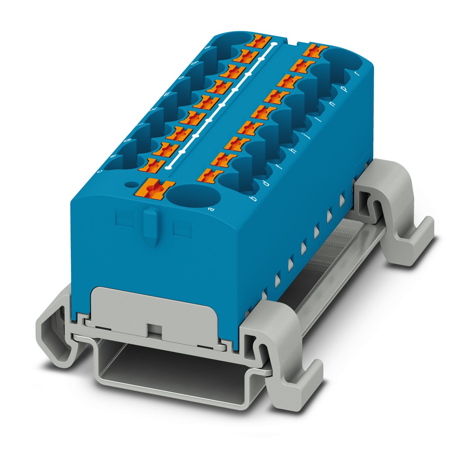
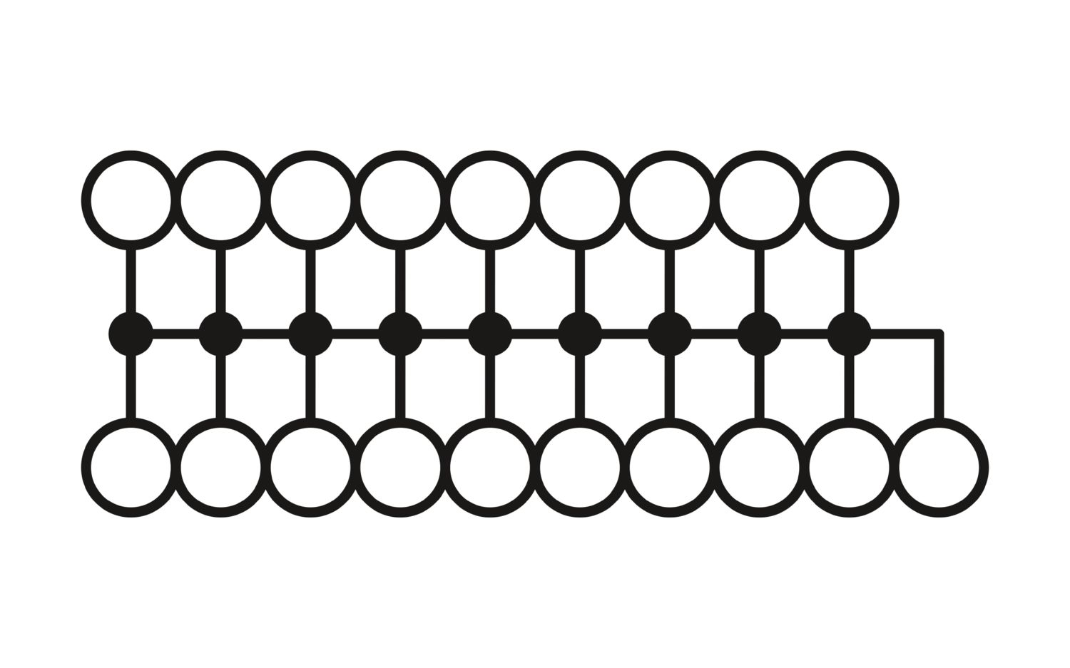
Distribution block, nom. voltage: 800 V, nominal current: 32 A, number of connections: 19, connection method: Push-in connection, Rated cross section: 4 mm2, Load contact, cross section: 0.2 mm2 - 6 mm2, Push-in connection, Line contact, Rated cross section: 10 mm2, cross section: 0.5 mm2 - 10 mm2, mounting type: NS 35/7,5, NS 35/15, color: blue
| General | |
| Note | For power distribution applications, IEC 60364-4-43.2008; modified + corrigendum Okt. 2008 (DIN VDE 0100-430:2010-10) section 433.2 ff must be observed! |
| Product type | Distributor terminal block |
| Number of connections | 19 |
| Number of rows | 1 |
| Potentials | 1 |
| Insulation characteristics | |
| Overvoltage category | III |
| Degree of pollution | 3 |
| Rated surge voltage | 6 kV |
| Maximum power dissipation for nominal condition | 1.02 W |
| Service Entrance | yes |
| Number of connections per level | 19 |
| Nominal cross section | 4 mm² |
| Rated cross section AWG | 10 |
| Load contact | |
| Connection method | Push-in connection |
| Stripping length | 10 mm ... 12 mm |
| Internal cylindrical gage | A4 |
| Connection in acc. with standard | IEC 60947-7-1 |
| Conductor cross-section rigid | 0.2 mm² ... 6 mm² |
| Cross section AWG | 24 ... 10 (converted acc. to IEC) |
| Conductor cross-section flexible | 0.2 mm² ... 6 mm² |
| Conductor cross-section, flexible [AWG] | 24 ... 10 (converted acc. to IEC) |
| Conductor cross-section flexible (ferrule without plastic sleeve) | 0.2 mm² ... 4 mm² |
| Flexible conductor cross-section (ferrule with plastic sleeve) | 0.2 mm² ... 4 mm² |
| 2 conductors with the same cross section, flexible, with TWIN ferrule with plastic sleeve | 0.5 mm² ... 1 mm² |
| Nominal current | 32 A |
| Maximum load current | 41 A (with 6 mm² conductor connection) |
| Maximum total current | 63 A (The maximum load current of the individual terminal point must not be exceeded.) |
| Nominal voltage | 800 V |
| Nominal cross section | 4 mm² |
| Line contact | |
| Connection method | Push-in connection |
| Stripping length | 12 mm ... 14 mm |
| Connection in acc. with standard | IEC 60947-7-1 |
| Conductor cross-section rigid | 0.5 mm² ... 10 mm² |
| Cross section AWG | 24 ... 10 (converted acc. to IEC) |
| Conductor cross-section flexible | 0.5 mm² ... 10 mm² |
| Conductor cross-section, flexible [AWG] | 24 ... 10 (converted acc. to IEC) |
| Conductor cross-section flexible (ferrule without plastic sleeve) | 0.5 mm² ... 10 mm² |
| Flexible conductor cross-section (ferrule with plastic sleeve) | 0.5 mm² ... 10 mm² |
| 2 conductors with the same cross section, flexible, with TWIN ferrule with plastic sleeve | 0.75 mm² ... 2.5 mm² |
| Nominal current | 57 A |
| Maximum load current | 57 A (with 10 mm² conductor cross-section) |
| Maximum total current | 63 A (The maximum load current of the individual terminal point must not be exceeded.) |
| Nominal voltage | 800 V |
| Nominal cross section | 10 mm² |
| Load contact Connection cross sections directly pluggable | |
| Conductor cross-section rigid | 0.5 mm² ... 6 mm² |
| Conductor cross-section, rigid [AWG] | 20 ... 10 (converted acc. to IEC) |
| Conductor cross-section flexible (ferrule without plastic sleeve) | 0.75 mm² ... 4 mm² |
| Flexible conductor cross-section (ferrule with plastic sleeve) | 0.5 mm² ... 4 mm² |
| Line contact Connection cross sections directly pluggable | |
| Conductor cross-section rigid | 1.5 mm² ... 10 mm² |
| Conductor cross-section flexible (ferrule without plastic sleeve) | 2.5 mm² ... 10 mm² |
| Flexible conductor cross-section (ferrule with plastic sleeve) | 1.5 mm² ... 10 mm² |
| Width | 64.8 mm |
| Height | 45.7 mm |
| Depth on NS 35/7,5 | 30.9 mm |
| Color | blue (RAL 5015) |
| Flammability rating according to UL 94 | V0 |
| Insulating material group | I |
| Insulating material | PA |
| Static insulating material application in cold | -60 °C |
| Relative insulation material temperature index (Elec., UL 746 B) | 130 °C |
| Fire protection for rail vehicles (DIN EN 45545-2) R22 | HL 1 - HL 3 |
| Fire protection for rail vehicles (DIN EN 45545-2) R23 | HL 1 - HL 3 |
| Fire protection for rail vehicles (DIN EN 45545-2) R24 | HL 1 - HL 3 |
| Fire protection for rail vehicles (DIN EN 45545-2) R26 | HL 1 - HL 3 |
| Surface flammability NFPA 130 (ASTM E 162) | passed |
| Specific optical density of smoke NFPA 130 (ASTM E 662) | passed |
| Smoke gas toxicity NFPA 130 (SMP 800C) | passed |
| Surge voltage test | |
| Test voltage setpoint | 9.8 kV |
| Result | Test passed |
| Temperature-rise test | |
| Requirement temperature-rise test | Increase in temperature ≤ 45 K |
| Result | Test passed |
| Short-time withstand current 10 mm² | 1.2 kA |
| Short-time withstand current 4 mm² | 1.2 kA |
| Result | Test passed |
| Power-frequency withstand voltage | |
| Test voltage setpoint | 2 kV |
| Result | Test passed |
| Mechanical data | |
| Open side panel | No |
| Mechanical strength | |
| Result | Test passed |
| Attachment on the carrier | |
| Result | Test passed |
| Note | When aligning several blocks, it is recommended to either place a DIN rail adapter underneath the connection point or a flange element between the blocks. |
| For versions with 6 or 7 connections, it is enough to place one DIN rail adapter centrally per block and place flange elements after every other block. | |
| Depending on the application case and mechanical load, other arrangements of the mounting accessory can also be chosen. | |
| When using the DIN rail adapter PTFIX-NS35, an aligned block must not protrude by more than a half. | |
| Test for conductor damage and slackening | |
| Rotation speed | 10 rpm |
| Revolutions | 135 |
| Conductor cross-section/weight | 0.5 mm² / 0.3 kg |
| 10 mm² / 2 kg | |
| Result | Test passed |
| Aging | |
| Temperature cycles | 192 |
| Result | Test passed |
| Needle-flame test | |
| Time of exposure | 30 s |
| Result | Test passed |
| Oscillation/broadband noise | |
| Specification | DIN EN 50155 (VDE 0115-200):2018-05 |
| Spectrum | Long life test category 2, bogie-mounted |
| Frequency | f1 = 5 Hz to f2 = 250 Hz |
| ASD level | 6.12 (m/s²)²/Hz |
| Acceleration | 3.12g |
| Test duration per axis | 5 h |
| Test directions | X-, Y- and Z-axis |
| Result | Test passed |
| Shocks | |
| Specification | DIN EN 50155 (VDE 0115-200):2018-05 |
| Pulse shape | Half-sine |
| Acceleration | 30g |
| Shock duration | 18 ms |
| Number of shocks per direction | 3 |
| Test directions | X-, Y- and Z-axis (pos. and neg.) |
| Result | Test passed |
| Ambient conditions | |
| Ambient temperature (operation) | -60 °C ... 110 °C (Operating temperature range incl. self-heating; for max. short-term operating temperature, see RTI Elec.) |
| Ambient temperature (storage/transport) | -25 °C ... 60 °C (for a short time, not exceeding 24 h, -60 °C to +70 °C) |
| Ambient temperature (assembly) | -5 °C ... 70 °C |
| Ambient temperature (actuation) | -5 °C ... 70 °C |
| Permissible humidity (operation) | 20 % ... 90 % |
| Permissible humidity (storage/transport) | 30 % ... 70 % |
| Connection in acc. with standard | IEC 60947-7-1 |
| IEC 60947-7-1 |
| Mounting type | NS 35/7,5 |
| NS 35/15 |
| Item number | 3273770 |
| Packing unit | 8 pc |
| Minimum order quantity | 8 pc |
| Product key | BEA124 |
| GTIN | 4055626667874 |
| Weight per piece (including packing) | 52.2 g |
| Weight per piece (excluding packing) | 55.412 g |
| Customs tariff number | 85369010 |
| Country of origin | PL |
| ECLASS-13.0 | 27250118 |
| ECLASS-15.0 | 27250118 |
| ETIM 9.0 | EC000897 |
| UNSPSC 21.0 | 39121400 |
| Nominal voltage UN | Nominal current IN | Cross section AWG | Cross section mm2 | |
|---|---|---|---|---|
| keine | ||||
| 800 V | 57 A | - 10 | ||
| EU RoHS | |
| Fulfills EU RoHS substance requirements | Yes (No exemptions) |
| China RoHS | |
| Environment friendly use period (EFUP) |
EFUP-E
No hazardous substances above the limits
|
| EU REACH SVHC | |
| REACH candidate substance (CAS No.) | No substance above 0.1 wt% |