
VAL-SPP-T2-275-3+1-UT-R
-
Type 2 surge arrester
1466214
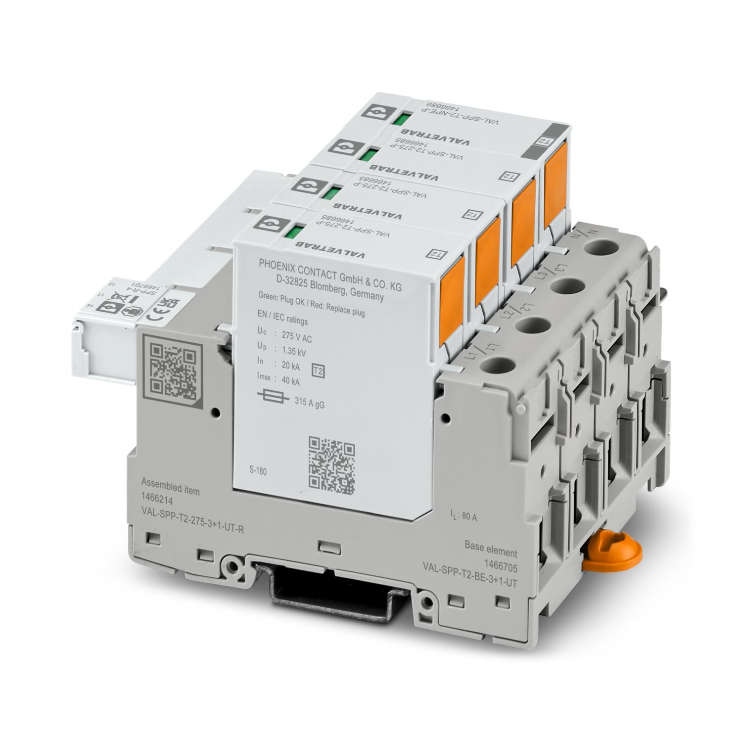

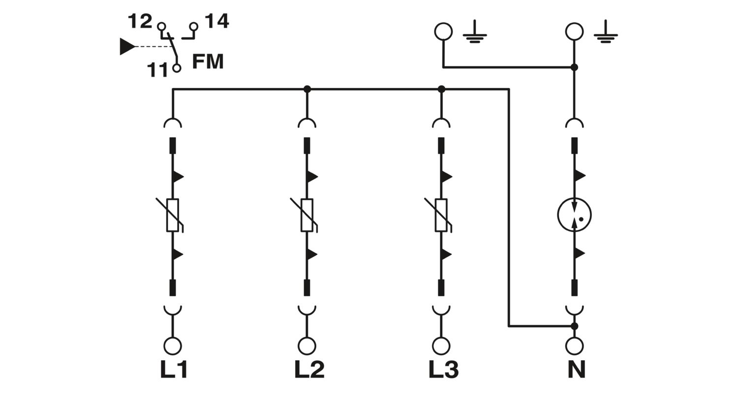
Plug-in surge arrester, in accordance with Type 2/Class II, for 3-phase power supply networks with separate N and PE (5-conductor system: L1, L2, L3, N, PE), with remote indication contact.
Product details
| Product type | Surge arrester |
| IEC test classification | II |
| EN type | T2 |
| IEC power supply system | TN-S |
| TT | |
| Type | DIN rail module, two-section, divisible |
| Environment | Indoor |
| Accessibility | Accessible |
| End-of-life mode | OCM |
| Surge protection fault message | Optical, remote indicator contact |
| Number of ports | One |
| Insulation characteristics | |
| Overvoltage category | III |
| II | |
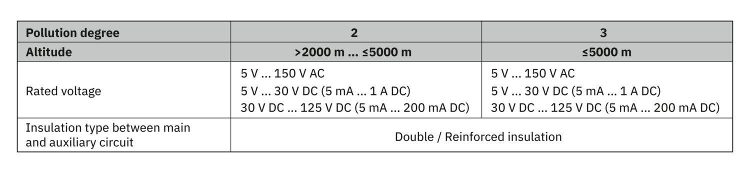
| Pollution degree (Main circuit) | 2 (For pollution degree 3, see Table 1 and Table 2) |
| Pollution degree (Auxiliary circuit) | 2 (For pollution degree 3, see Table 2) |
| Maximum power dissipation for nominal condition | ≤ 320 mVA |
| Indicator/remote signaling | |
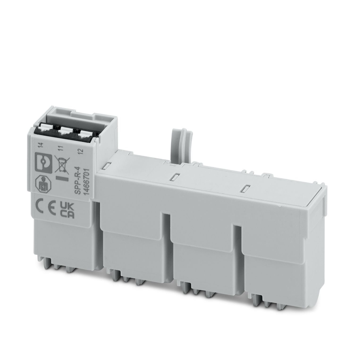
| Connection name | remote fault indicator contact (11, 12, 14) |
| Switching contact | Changeover contact |
| AC operating voltage | 5 V AC ... 250 V AC |
| AC operating current | 5 mA AC ... 1 A AC |
| DC operating voltage | 5 V DC ... 30 V DC |
| DC operating current | 5 mA DC ... 1 A DC |
| DC operating voltage | 5 V DC ... 125 V DC |
| DC operating current | 5 mA DC ... 200 mA DC |
| Max. required back-up fuse | 1 A (gG) |
| Insulation type (between the main and auxiliary circuit) | Double/reinforced insulation |
| Indicator/remote signaling | |
| Connection name | remote fault indicator contact (11, 12, 14) |
| protection circuit (L1, L2, L3, N, PE) | |
| Connection method | Screw connection |
| Screw thread | M5 |
| Stripping length | 18 mm |
| Conductor cross-section rigid | 1.5 mm² ... 50 mm² |
| Conductor cross-section flexible | 1.5 mm² ... 35 mm² |
| Conductor cross-section AWG | 14 ... 2 |
| Conductor cross-section, flexible, with ferrule, without plastic sleeve | 1.5 mm² ... 25 mm² |
| Conductor cross-section, flexible, with ferrule, with plastic sleeve | 1.5 mm² ... 35 mm² |
| 2 conductors with same cross section, rigid | 1.5 mm² ... 16 mm² |
| 2 conductors with same cross section, flexible | 1.5 mm² ... 16 mm² |
| 2 conductors with same cross section, flexible, with ferrule without plastic sleeve | 1.5 mm² ... 16 mm² |
| 2 conductors with the same cross section, flexible, with ferrule with plastic sleeve | 1.5 mm² ... 10 mm² |
| 2 conductors with the same cross section, flexible, with TWIN ferrule with plastic sleeve | 1.5 mm² ... 16 mm² |
| Drive size | PZSL 2 |
| PZ/S 2 | |
| Tightening torque | 3 Nm ... 3.5 Nm |
| Biconnect terminal block | |
| Connection method | Fork-type cable lug |
| Conductor cross-section flexible | 1.5 mm² ... 25 mm² |
| remote fault indicator contact (11, 12, 14) | |
| Connection method | Push-in connection |
| Stripping length | 8 mm |
| Conductor cross-section rigid | 0.25 mm² ... 1.5 mm² |
| Conductor cross-section flexible | 0.25 mm² ... 1.5 mm² |
| Conductor cross-section AWG | 24 ... 16 |
| Conductor cross-section, flexible, with ferrule, without plastic sleeve | 0.25 mm² ... 1 mm² |
| Conductor cross-section, flexible, with ferrule, with plastic sleeve | 0.25 mm² ... 1.5 mm² |
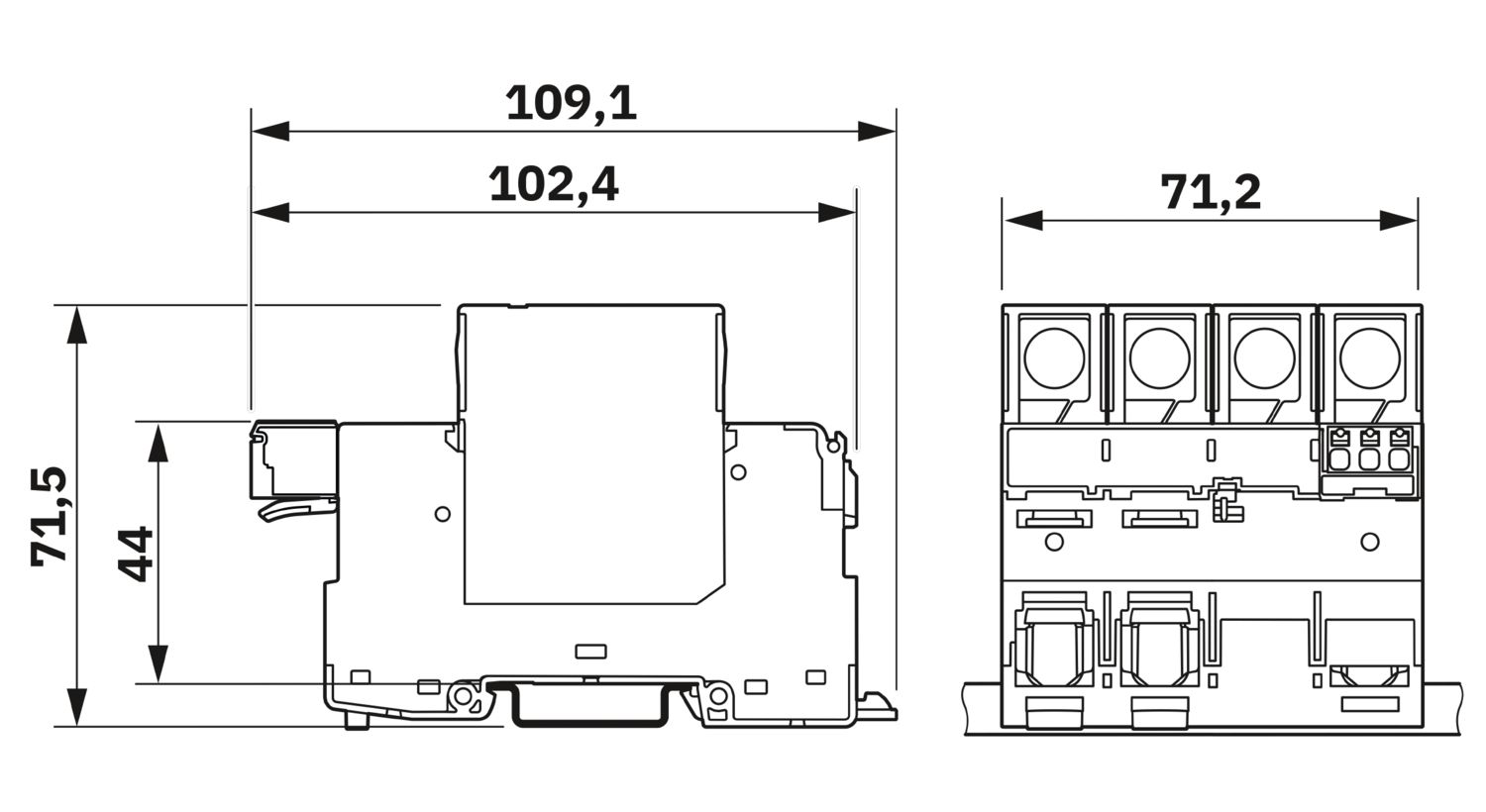
| Dimensional drawing |
|
| Width | 71.2 mm |
| Height | 109.1 mm |
| Depth | 71.5 mm (incl. DIN rail 7.5 mm) |
| Horizontal pitch | 4 HP |
| Color | gray (RAL 7042) |
| light gray (RAL 7035) | |
| Material Housing | PA 6.6-FR 20 % GF |
| PA 6.6 | |
| PBT | |
| Flammability rating according to UL 94 | V-0 |
| Insulating material | PA 6.6-FR 20 % GF |
| PA 6.6 | |
| PBT |
| Mode of protection | L-N |
| L-PE | |
| N-PE | |
| Nominal voltage UN | 240/415 V AC ±10 % (TN-S) |
| 240/415 V AC ±10 % (TT) | |
| Nominal frequency | 50/60 Hz |
| Maximum continuous operating voltage UC (L-N) | 275 V AC |
| Maximum continuous operating voltage UC (L-PE) | 275 V AC |
| Maximum continuous operating voltage UC (N-PE) | 305 V AC |
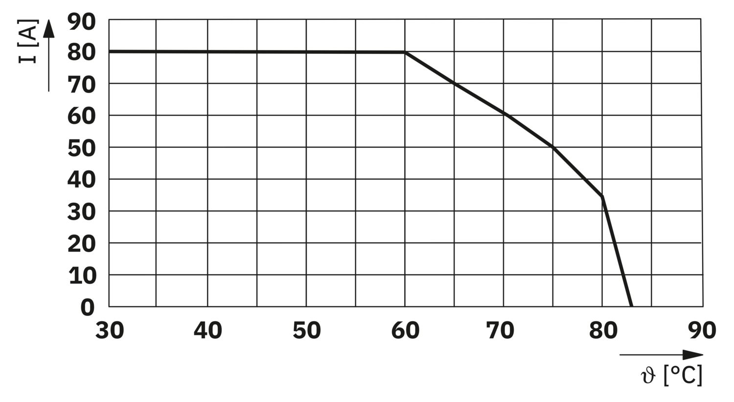
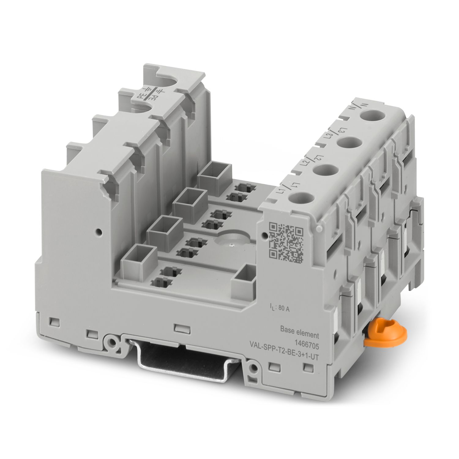
| Rated load current IL | 80 A (25 mm²) |
| Protective conductor current IPE | ≤ 5 µA |
| Continuous current IC (L-N) | ≤ 0.4 mA |
| Continuous current IC (L-PE) | ≤ 5 µA |
| Continuous current IC (N-PE) | ≤ 5 µA |
| Maximum power dissipation for nominal condition | ≤ 320 mVA |
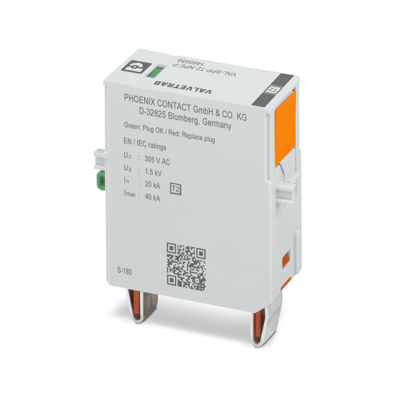
| Nominal discharge current In (8/20) µs | 20 kA |
| Max. discharge current Imax (8/20)µs | 40 kA |
| Total discharge current ITotal (8/20) µs | 40 kA |
| Follow current interrupt rating Ifi (N-PE) | 100 A |
| Short-circuit current rating ISCCR | 50 kA |
| Voltage protection level Up (L-N) | ≤ 1.35 kV |
| Voltage protection level Up (L-PE) | ≤ 1.6 kV |
| Voltage protection level Up (N-PE) | ≤ 1.5 kV |
| Front-of-wave sparkover voltage at 6 kV (1.2/50) µs (L-PE) | ≤ 1.6 kV |
| Front-of-wave sparkover voltage at 6 kV (1.2/50) µs (N-PE) | ≤ 1.5 kV |
| Residual voltage Ures (L-N) | ≤ 1.35 kV (at In) |
| ≤ 1.1 kV (at 10 kA) | |
| ≤ 1 kV (at 5 kA) | |
| ≤ 0.9 kV (at 3 kA) | |
| Residual voltage Ures (L-PE) | ≤ 1.6 kV (at In) |
| ≤ 1.3 kV (at 10 kA) | |
| ≤ 1.1 kV (at 5 kA) | |
| ≤ 1 kV (at 3 kA) | |
| Residual voltage Ures (N-PE) | ≤ 0.5 kV (at In) |
| ≤ 0.4 kV (at 10 kA) | |
| ≤ 0.3 kV (at 5 kA) | |
| ≤ 0.1 kV (at 3 kA) | |
| TOV behavior at UT (L-N) | 350 V AC (5 s / withstand mode) |
| 460 V AC (120 min / safe failure mode) | |
| TOV behavior at UT (L-PE) | 460 V AC (120 min / withstand mode) |
| 1464 V AC (200 ms / withstand mode) | |
| TOV behavior at UT (N-PE) | 1200 V AC (200 ms/withstand mode) |
| Response time tA (L-N) | ≤ 25 ns |
| Response time tA (L-PE) | ≤ 100 ns |
| Response time tA (N-PE) | ≤ 100 ns |
| Max. backup fuse with V-type through wiring | 80 A (gG) |
| Max. backup fuse with branch wiring | 315 A (gG) |
| Ambient conditions | |
| Degree of protection | IP20C (under touch protection cover) |
| Ambient temperature (operation) | -40 °C ... 85 °C |
| Ambient temperature (storage/transport) | -40 °C ... 85 °C |
| Ambient temperature (assembly) | -5 °C ... 50 °C |
| Altitude | ≤ 2000 m (amsl) |
| For higher altitudes, see Table 1 and Table 2 | |
| Permissible humidity (operation) | 5 % ... 95 % |
| Shock (operation) | 25g (Half-sine / 11 ms / 3x ±X, ±Y, ±Z) |
| Vibration (operation) | 5g (10 ... 150 Hz / 2.5 h / X, Y, Z) |
| 0,7g (5 ... 100 Hz / X, Y, Z - according to GL ) | |
| Standards/specifications | IEC 61643-11 |
| Note | 2025 |
| Standards/specifications | EN IEC 61643-11 |
| Note | 2025 + A11:2025 |
| Standards/specifications | EN 61643-11 |
| Note | 2012 + A11:2018 |
| Mounting type | DIN rail: 35 mm |
| Mounting method | fixed |
Your advantages
Easy and safe installation with forward-thinking handling and safety features
Reliable system protection with maximum performance and endurance
Can be used in a wide range of applications due to the optimized design and broad portfolio
Simple planning due to comprehensive digital data and selectors