
TRIO POWER power supplies with standard functionality
The TRIO POWER power supply range with push-in connection has been perfected for use in machine building. All functions and the space-saving design of the single and three-phase modules are optimally tailored to the stringent requirements. Under challenging ambient conditions, the power supply units, which feature an extremely robust electrical and mechanical design, ensure the reliable supply of all loads.
TRIO-PS-2G/3AC/24DC/40
-
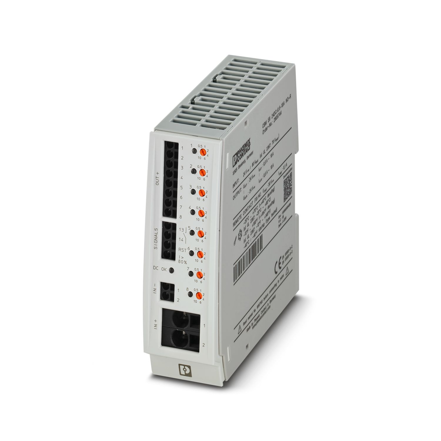
Power supply
2903156
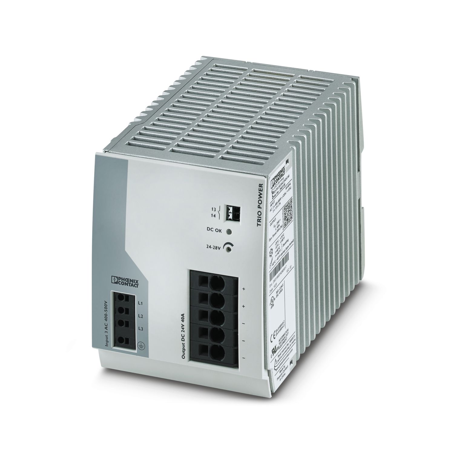
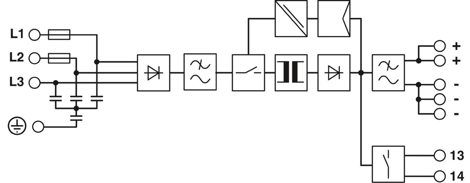
Primary-switched TRIO power supply for DIN rail mounting, input: 3-phase, output: 24 V DC/40 A, dynamic boost, tool-free fast connection technology for solid and stranded conductors with ferrule
Product details
UL Recognized
Approval ID: E211944EAC
Approval ID: RU S-DE.BL08.W.00764UL Listed
Approval ID: E123528cUL Listed
Approval ID: E123528EAC
Approval ID: RU S-DE.BL08.W.00764IECEE CB Scheme
Approval ID: DE/PTZ/0037/A1cUL Listed
Approval ID: E199827UL Listed
Approval ID: FILE E 199827
Your advantages
Save time and costs, thanks to the Push-in connection and narrow design
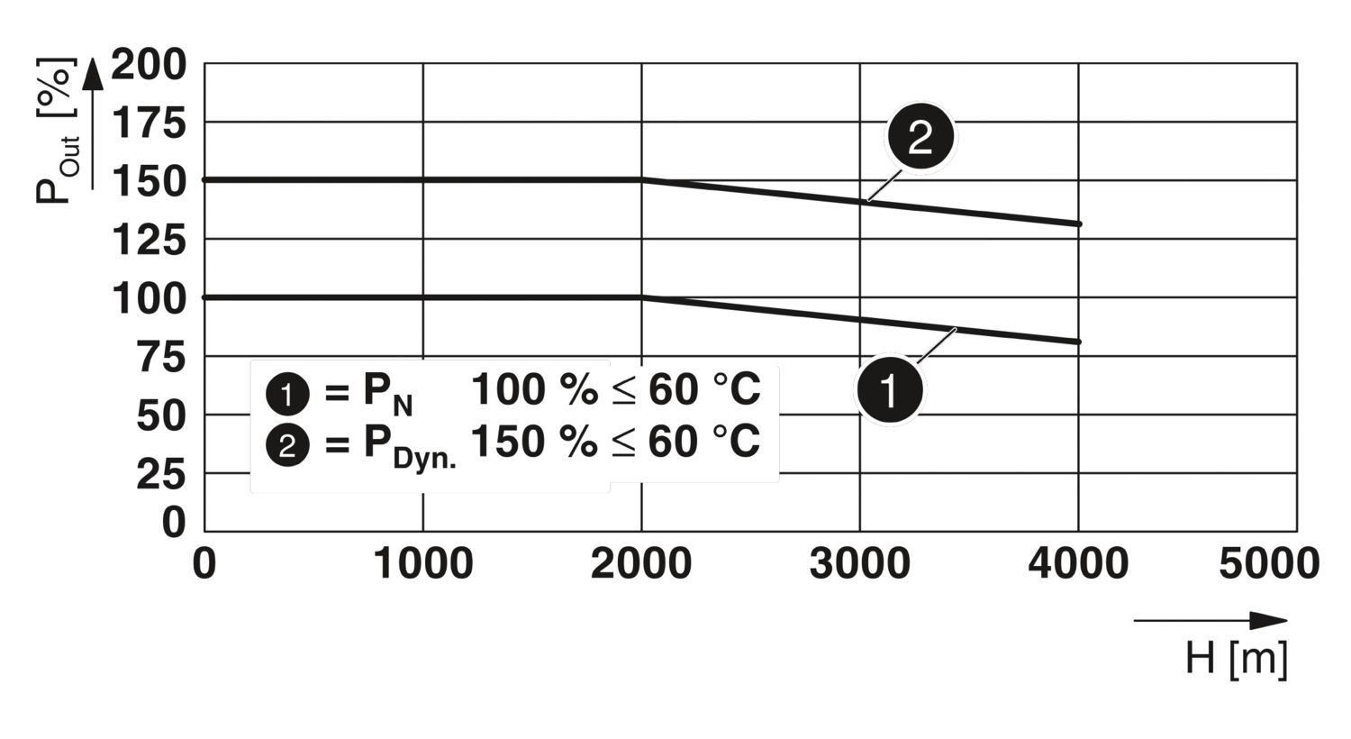
Increase system availability, thanks to dynamic boost with 150 % of the nominal current for 5 seconds
Maximum flexibility due to the wide temperature range from -25°C to +70°C and device startup at -40°C
Electrically robust, thanks to high electric strength
Mechanically robust, thanks to high vibration and shock resistance