QUINT POWER power supplies with maximum functionality
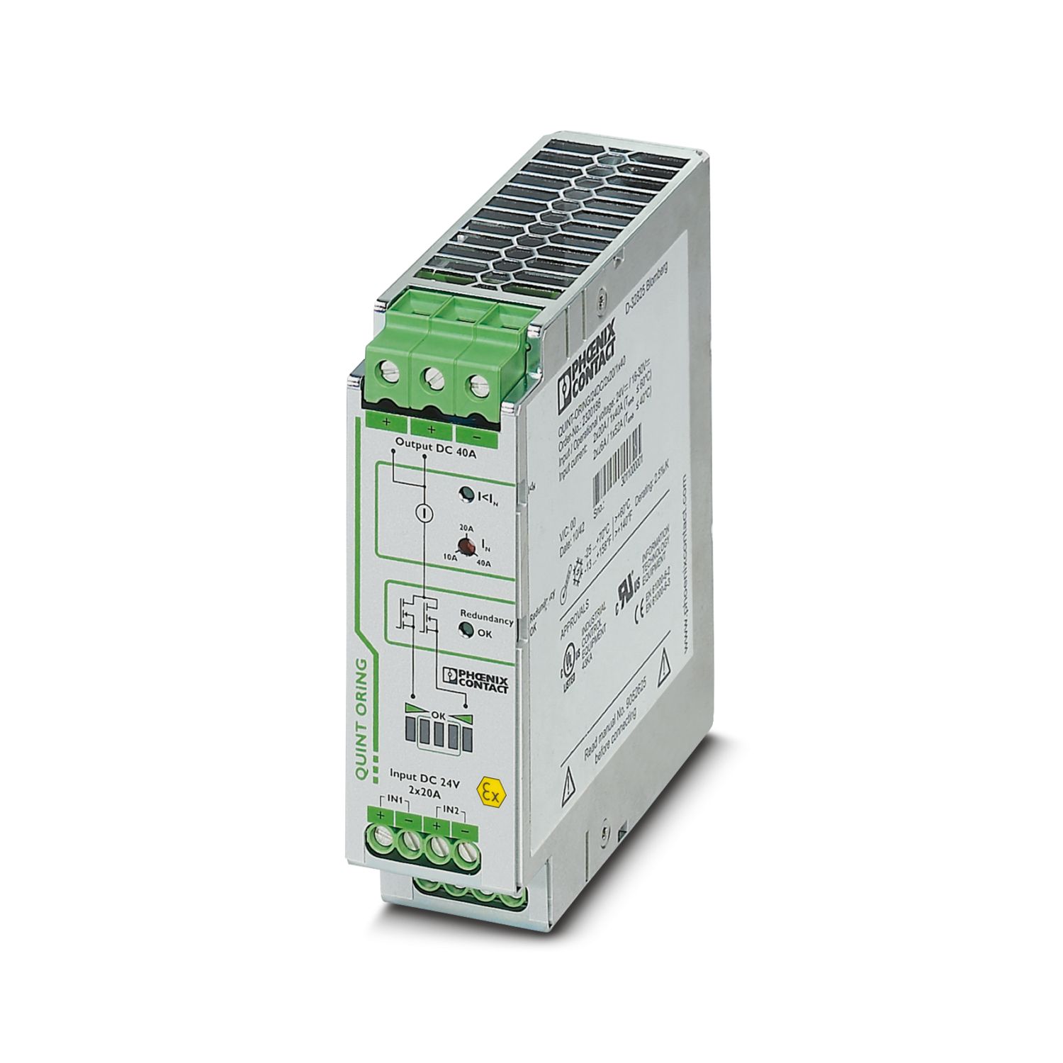
QUINT POWER circuit breakers magnetically and therefore quickly trip at six times the nominal current, for selective and therefore cost-effective system protection. In addition, the high system availability is ensured by preventive function monitoring which reports critical operating states before errors can occur.
Reliable starting of heavy loads takes place via the static power reserve POWER BOOST. Thanks to the adjustable voltage, all ranges between 18 V DC ... 29.5 V DC are covered.
QUINT-PS/3AC/24DC/20/CO
-
Power supply, with protective coating
2320924
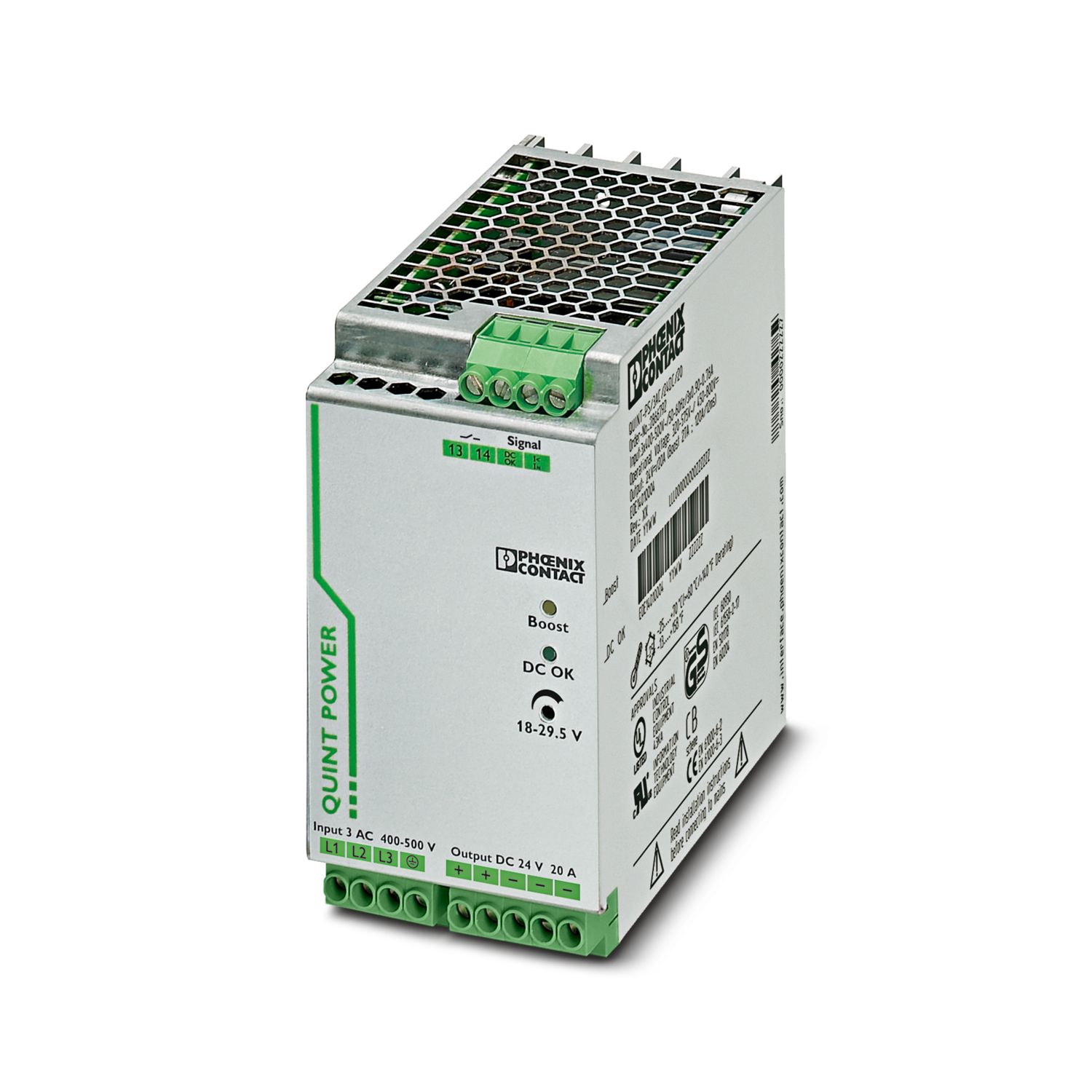
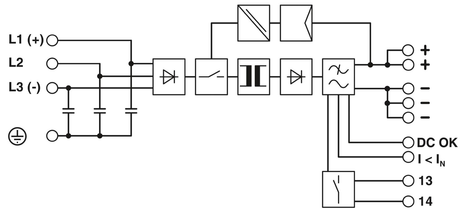
Primary-switched power supply unit QUINT POWER, Screw connection, SFB Technology (Selective Fuse Breaking), input: 3-phase, output: 24 V DC / 20 A
Product details
AC operation | |
Nominal input voltage range | 3x 400 V AC ... 500 V AC |
Input voltage range | 3x 320 V AC ... 575 V AC |
2x 360 V AC ... 575 V AC | |
450 V DC ... 800 V DC | |
Voltage type of supply voltage | AC/DC |
Inrush current | < 20 A (typical) |
Inrush current integral (I2t) | < 3.2 A2s |
AC frequency range | 45 Hz ... 65 Hz |
Frequency range DC | 0 Hz |
Mains buffering time | typ. 28 ms (400 V AC) |
typ. 43 ms (500 V AC) | |
Current consumption | 3x 1.6 A (400 V AC) |
3x 1.3 A (500 V AC) | |
0.9 A (600 V DC) | |
Nominal power consumption | 783 VA |
Protective circuit | Transient surge protection; Varistor, gas-filled surge arrester |
Typical response time | < 0.16 s |
Permissible backup fuse | B6 B10 B16 |
Permissible DC backup fuse | DC: Connect a suitable fuse upstream |
Recommended breaker for input protection | 6 A ... 16 A (AC: Characteristics B, C, D, K) |
Discharge current to PE | < 3.5 mA |
Efficiency | > 93 % (at 400 V AC and nominal values) |
Nominal output voltage | 24 V DC ±1 % |
Setting range of the output voltage (USet) | 18 V DC ... 29.5 V DC (> 24 V DC, constant capacity restricted) |
Nominal output current (IN) | 20 A (-25 °C ... 60 °C, UOUT = 24 V DC) |
POWER BOOST (IBoost) | 26 A (-25 °C ... 40 °C permanent, UOUT = 24 V DC ) |
Selective Fuse Breaking (ISFB) | 120 A (12 ms) |
Magnetic circuit breaker tripping | B2 / B4 / B6 / B10 / B16 / C2 / C4 / C6 |
Derating | 60 °C ... 70 °C (2.5 %/K) |
Feedback voltage resistance | max. 32 V DC |
Protection against overvoltage at the output (OVP) | < 32 V DC |
Control deviation | < 1 % (change in load, static 10 % ... 90 %) |
< 3 % (change in load, dynamic 10 % ... 90 %) | |
< 0.1 % (change in input voltage ±10 %) | |
Residual ripple | < 40 mVPP (with nominal values) |
Output power | 480 W |
Peak switching voltages nominal load | < 40 mVPP (at nominal values, 20 MHz) |
Maximum no-load power dissipation | 11 W |
Power loss nominal load max. | 40 W |
Rise time | < 0.05 s (UOUT (10 % ... 90 %)) |
Connection in parallel | yes, for redundancy and increased capacity |
Connection in series | yes |
Signal: DC OK active | |
Output description | UOUT > 0.9 x UN: High signal |
Switching voltage range | 18 V ... 24 V |
Output voltage | + 24 V DC |
Maximum inrush current | ≤ 20 mA (short-circuit-proof) |
Continuous load current | ≤ 20 mA |
Signal: DC OK floating | |
Output description | Relay contact, UOUT > 0.9 x UN: Contact closed |
Maximum switching voltage | 30 V AC/DC |
24 V DC | |
Maximum inrush current | 0.5 A |
1 A | |
Continuous load current | ≤ 1 A |
Signal: POWER BOOST, active | |
Output description | IOUT < IN: High signal |
Switching voltage range | 18 V ... 24 V |
Output voltage | + 24 V DC |
Maximum inrush current | ≤ 20 mA (short-circuit-proof) |
Continuous load current | ≤ 20 mA |
Input | |
Connection method | Screw connection |
Conductor cross section, rigid min. | 0.2 mm² |
Conductor cross section, rigid max. | 6 mm² |
Conductor cross section flexible min. | 0.2 mm² |
Conductor cross section flexible max. | 4 mm² |
Conductor cross section AWG min. | 18 |
Conductor cross section AWG max. | 10 |
Stripping length | 7 mm |
Screw thread | M4 |
Tightening torque, min | 0.5 Nm |
Tightening torque max | 0.6 Nm |
Output | |
Connection method | Screw connection |
Conductor cross section, rigid min. | 0.2 mm² |
Conductor cross section, rigid max. | 6 mm² |
Conductor cross section flexible min. | 0.2 mm² |
Conductor cross section flexible max. | 4 mm² |
Conductor cross section AWG min. | 12 |
Conductor cross section AWG max. | 10 |
Stripping length | 7 mm |
Screw thread | M4 |
Tightening torque, min | 0.5 Nm |
Tightening torque max | 0.6 Nm |
Signal | |
Conductor cross section, rigid min. | 0.2 mm² |
Conductor cross section, rigid max. | 6 mm² |
Conductor cross section flexible min. | 0.2 mm² |
Conductor cross section flexible max. | 4 mm² |
Conductor cross section AWG min. | 18 |
Conductor cross section AWG max. | 10 |
Screw thread | M4 |
Tightening torque, min | 0.5 Nm |
Tightening torque max | 0.6 Nm |
Types of signaling | LED |
Active switching output | |
Relay contact | |
Signal output: DC OK active | |
Status display | UOUT > 0.9 x UN: "DC OK" LED green |
Note on status display | UOUT < 0.9 x UN: Flashing "DC OK" LED |
Color | green |
Note on status display | LED flashing |
Signal output: DC OK floating | |
Status display | UOUT > 0.9 x UN: "DC OK" LED green |
Note on status display | UOUT < 0.9 x UN: Flashing "DC OK" LED |
Color | green |
Note on status display | LED flashing |
Signal output: POWER BOOST, active | |
Status display | IOUT > IN: LED "BOOST" yellow |
Color | yellow |
Number of phases | 3.00 |
Insulation voltage input/output | 4 kV AC (type test) |
2 kV AC (routine test) | |
Insulation voltage output / PE | 500 V DC (routine test) |
Insulation voltage input / PE | 3.5 kV AC (type test) |
2 kV AC (routine test) |
Product type | Power supply |
Product family | QUINT POWER |
MTBF (IEC 61709, SN 29500) | > 900000 h (25 °C) |
> 534000 h (40 °C) | |
Insulation characteristics | |
Protection class | I |
Degree of pollution | 2 |
Width | 69 mm |
Height | 130 mm |
Depth | 125 mm |
Installation dimensions | |
Installation distance right/left | 5 mm / 5 mm |
Installation distance top/bottom | 50 mm / 50 mm |
Alternative assembly | |
Width | 125 mm |
Height | 130 mm |
Depth | 72 mm |
Assembly note | alignable: PN ≥50%, 5 mm horizontally, 15 mm next to active components, 50 mm vertically alignable: PN <50%, 0 mm horizontally, 40 mm vertically top, 20 mm vertically bottom |
Mounting position | horizontal DIN rail NS 35, EN 60715 |
With protective coating | yes |
Housing material | Metal |
Housing material | Steel sheet, zinc-plated |
Type of housing | Steel sheet, zinc-plated |
Ambient conditions | |
Degree of protection | IP20 |
Ambient temperature (operation) | -40 °C ... 70 °C (> 60 °C Derating: 2,5 %/K) |
Ambient temperature (storage/transport) | -40 °C ... 85 °C |
Ambient temperature (start-up type tested) | -40 °C |
Maximum altitude | 5000 m |
Climatic class | 3K3 (in acc. with EN 60721) |
Max. permissible relative humidity (operation) | 100 % (at 25 °C, non-condensing) |
Shock | 18 ms, 30g, in each space direction (according to IEC 60068-2-27) |
Vibration (operation) | < 15 Hz, amplitude ±2.5 mm (according to IEC 60068-2-6) |
15 Hz ... 150 Hz, 2.3g, 90 min. |
Rail applications | EN 50121-4 |
EN 50121-3-2 | |
Standard – Limitation of mains harmonic currents | EN 61000-3-2 |
Standard - Electrical safety | IEC 61010-2-201 (SELV) |
Standard - Equipment safety | BG (design tested) |
Standard – Protection against shock currents, basic requirements for protective separation in electrical equipment | EN 50178 |
Standard – Safety extra-low voltage | IEC 61010-1 (SELV) |
IEC 61010-2-201 (PELV) | |
Standard - Safe isolation | IEC 61010-2-201 |
Standard - safety for equipment for measurement, control, and laboratory use | IEC 61010-1 |
Noxious gas test | ISA-S71.04-1985 G3 Harsh Group A |
Approval - requirement of the semiconductor industry with regard to mains voltage dips | SEMI F47-0706 Compliance Certificate |
Overvoltage category | |
EN 62477-1 | III |
Fire protection in rail vehicles | |
Standard designation | Fire protection in rail vehicles |
Standards/specifications | EN 45545-2 (HL3) |
CSA | CAN/CSA-C22.2 No. 60950-1-07 |
CSA-C22.2 No. 107.1-01 | |
Shipbuilding approval | DNV GL (EMC B), ABS, LR, RINA, NK, BV |
UL approvals | UL/C-UL listed UL 508 |
UL/C-UL Recognized UL 60950-1 (3-wire + PE, star net) | |
UL ANSI/ISA-12.12.01 Class I, Division 2, Groups A, B, C, D T4 (Hazardous Location) |
Electromagnetic compatibility | Conformance with EMC Directive 2014/30/EU |
Low Voltage Directive | Conformance with Low Voltage Directive 2014/35/EC |
EMC requirements for noise emission | EN 61000-6-3 |
EN 61000-6-4 | |
EMC requirements for noise immunity | EN 61000-6-1 |
EN 61000-6-2 | |
Noise emission | |
Standards/regulations | EN 55011 (EN 55022) |
Electrostatic discharge | |
Standards/regulations | EN 61000-4-2 |
Electrostatic discharge | |
Contact discharge | 8 kV (Test Level 4) |
Discharge in air | 15 kV (Test Level 4) |
Comments | Criterion A |
Electromagnetic HF field | |
Standards/regulations | EN 61000-4-3 |
Electromagnetic HF field | |
Frequency range | 80 MHz ... 1 GHz |
Test field strength | 20 V/m (Test Level 3) |
Frequency range | 1 GHz ... 2 GHz |
Test field strength | 10 V/m (Test Level 3) |
Frequency range | 2 GHz ... 3 GHz |
Test field strength | 10 V/m (Test Level 3) |
Comments | Criterion A |
Fast transients (burst) | |
Standards/regulations | EN 61000-4-4 |
Fast transients (burst) | |
Input | 4 kV (Test Level 4 - asymmetrical) |
Output | 2 kV (Test Level 3 - asymmetrical) |
Signal | 2 kV (Test Level 4 - asymmetrical) |
Comments | Criterion B |
Surge voltage load (surge) | |
Standards/regulations | EN 61000-4-5 |
Surge voltage load (surge) | |
Input | 1 kV (Test Level 2 - symmetrical) |
2 kV (Test Level 3 - asymmetrical) | |
Output | 0.5 kV (Test Level 1 - symmetrical) |
0.5 kV (Test Level 1 - asymmetrical) | |
Signal | 1 kV (Test Level 2 - asymmetrical) |
Comments | Criterion B |
Conducted interference | |
Standards/regulations | EN 61000-4-6 |
Conducted interference | |
Input/output/signal | asymmetrical |
Frequency range | 0.15 MHz ... 80 MHz |
Comments | Criterion A |
Voltage | 10 V (Test Level 3) |
Emitted interference | |
Standards/regulations | EN 61000-6-3 |
Radio interference voltage in acc. with EN 55011 | EN 55011 (EN 55022) Class B, area of application: Industry and residential |
Emitted radio interference in acc. with EN 55011 | EN 55011 (EN 55022) Class B, area of application: Industry and residential |
Criteria | |
Criterion A | Normal operating behavior within the specified limits. |
Criterion B | Temporary impairment to operational behavior that is corrected by the device itself. |
Item number | 2320924 |
Packing unit | 1 pc |
Minimum order quantity | 1 pc |
Sales key | CM11 |
Product key | CMPQ33 |
Catalog page | Page 247 (C-4-2019) |
GTIN | 4046356605601 |
Weight per piece (including packing) | 1,834.5 g |
Weight per piece (excluding packing) | 1,504 g |
Customs tariff number | 85044095 |
Country of origin | TH |
ECLASS
ECLASS-11.0 | 27040701 |
ECLASS-13.0 | 27040701 |
ECLASS-12.0 | 27040701 |
ETIM
ETIM 9.0 | EC002540 |
UNSPSC
UNSPSC 21.0 | 39121000 |
UL Recognized
Approval ID: E211944IECEE CB Scheme
Approval ID: SI-2794EAC
Approval ID: EAC-ZulassungEAC
Approval ID: RU S-DE.BL08.W.00764UL Listed
Approval ID: E123528Type approved
Approval ID: SI-SIQ BG 005/002EAC
Approval ID: RU S-DE.BL08.W.00764DNV
Approval ID: TAA000030XcCSAus
Approval ID: 1925529cUL Listed
Approval ID: E199827UL Listed
Approval ID: E199827cULus Recognized
cULus Listed
EU RoHS | |
Fulfills EU RoHS substance requirements | Yes |
Exemption | 7(a), 7(c)-I |
China RoHS | |
Environment friendly use period (EFUP) |
EFUP-25
An article-related China RoHS declaration table can be found in the download area for the respective article under "Manufacturer declaration". For all articles with EFUP-E, no China RoHS declaration table issued and required.
|
EU REACH SVHC | |
REACH candidate substance (CAS No.) | Lead (CAS: 7439-92-1) |
SCIP | cd343214-2513-402d-b25f-7d14c2f93343 |
Compatible products
-
UTA 107 - DIN rail adapter 2853983
-
UWA 182/52 - Mounting adapter 2938235
-
QUINT-PS-ADAPTERS7/2 - Mounting adapter 2938206
-
QUINT-PS/FAN/4 - Fan 2320076
-
QUINT-DIODE/12-24DC/2X20/1X40 - Redundancy module 2320157
-
TRIO-DIODE/12-24DC/2X10/1X20 - Redundancy module 2866514
-
QUINT-ORING/24DC/2X20/1X40 - Redundancy module, with protective coating 2320186
-
CB TM1 1A SFB P - Thermal-magnetic device circuit breaker 2800836
-
CB TM1 2A SFB P - Thermal-magnetic device circuit breaker 2800837
-
CB TM1 3A SFB P - Thermal-magnetic device circuit breaker 2800838
-
CB TM1 4A SFB P - Thermal-magnetic device circuit breaker 2800839
-
CB TM1 5A SFB P - Thermal-magnetic device circuit breaker 2800840
-
CB TM1 6A SFB P - Thermal-magnetic device circuit breaker 2800841
-
CB TM1 8A SFB P - Thermal-magnetic device circuit breaker 2800842
-
CB TM1 10A SFB P - Thermal-magnetic device circuit breaker 2800843
-
CB TM1 12A SFB P - Thermal-magnetic device circuit breaker 2800844
-
CB TM1 16A SFB P - Thermal-magnetic device circuit breaker 2800845
-
PLT-SEC-T3-3S-230-FM - Type 3 surge protection device 2905230
-
PLT-SEC-T3-24-FM-UT - Type 3 surge protection device 2907916
Your advantages
For superior system availability
Reliable starting of difficult loads with the static POWER BOOST power reserve with up to 1.5 times the nominal current permanently
Fast tripping of standard circuit breakers with dynamic power reserve SFB (selective fuse breaking) technology with up to 6 times the nominal current for 12 ms
Preventive function monitoring
Optimum protection with dip coating for 100 % humidity
PHOENIX CONTACT
586 Fulling Mill Road, Middletown, PA 17057