TRIO-DIODE/12-24DC/2X10/1X20 - Redundancy module
2866514

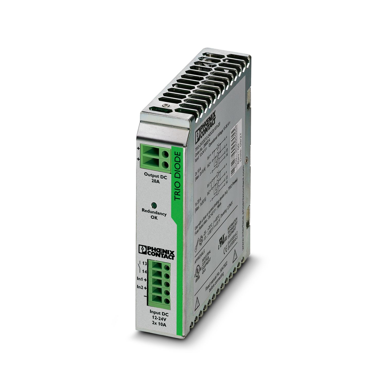
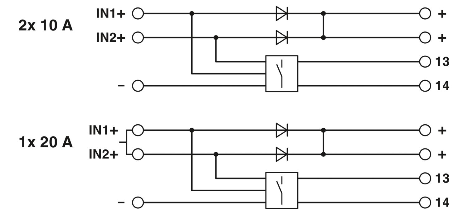
Redundancy module with function monitoring, 12 ... 24 V DC, 2x 10 A, 1x 20 A


Product Details


TRIO DIODE is the DIN-rail mountable redundancy module from the TRIO POWER product range.
Using the redundancy module, it is possible for two power supply units of the same type connected in parallel on the output side to increase performance or for redundancy to be 100 % isolated from one another.
Redundant systems are used in systems that place particularly high demands on operational reliability. The connected power supply units must be large enough that the total current requirements of all loads can be met by one power supply unit. The redundant structure of the power supply therefore ensures long-term, permanent system availability.
In the event of an internal device fault or failure of the mains power supply on the primary side, the other device automatically takes over the entire power supply of the loads without interruption. The floating signal contact and LED immediately indicate the loss of redundancy.


DC operation
Nominal input voltage range 12 V DC ... 24 V DC
Input voltage range 10 V DC ... 30 V DC
Input voltage range DC 10 V DC ... 30 V DC
Voltage type of supply voltage DC
Reverse polarity protection < yes60 V
Nominal input current (IN) 2x 10 A (-25 °C ... 55 °C)
1x 20 A (-25 °C ... 55 °C)
Maximum current Imax 2x 15 A (-25°C ... 40°C)
1x 30 A (-25°C ... 40°C)
Transient surge protection Varistor
Voltage drop, input/output 0.5 V

Efficiency > 97 %
Output voltage UIn -
Setting range of the output voltage (USet) 12 V DC ... 24 V DC
Nominal output current (IN) 20 A (Increasing power)
10 A (Redundancy)
Derating 55 °C ... 70 °C (2.5%/K)
Power loss nominal load max. 7 W (IOUT = 10 A)
Connection in series No
Signal: Floating redundancy OK
Output description Contact closed when UIN1 & UIN2 > 8 V
Maximum switching voltage max. 60 V DC
Maximum inrush current ≤ 100 mA (short-circuit-proof)

Input
Connection method Screw connection
Conductor cross section solid min. 0.2 mm²
Conductor cross section solid max. 2.5 mm²
Conductor cross section flexible min. 0.2 mm²
Conductor cross section flexible max. 2.5 mm²
Conductor cross section AWG min. 24
Conductor cross section AWG max. 14
Stripping length 9 mm
Screw thread M2,5
Tightening torque, min 0.4 Nm
Tightening torque max 0.5 Nm
Output
Connection method Screw connection
Conductor cross section solid min. 0.5 mm²
Conductor cross section solid max. 6 mm²
Conductor cross section flexible min. 0.5 mm²
Conductor cross section flexible max. 4 mm²
Conductor cross section AWG min. 20
Conductor cross section AWG max. 10
Stripping length 14 mm
Screw thread M3
Tightening torque, min 0.5 Nm
Tightening torque max 0.6 Nm
Signal
Conductor cross section solid min. 0.2 mm²
Conductor cross section solid max. 2.5 mm²
Conductor cross section flexible min. 0.2 mm²
Conductor cross section flexible max. 2.5 mm²
Conductor cross section AWG min. 24
Conductor cross section AWG max. 14
Screw thread M2,5
Tightening torque, min 0.4 Nm
Tightening torque max 0.5 Nm

Types of signaling LED
Relay contact
Signal output: Floating redundancy OK
Status display LED redundancy OK
Note on status display UIN1& UIN2 > 8 V: LED lights up green

Insulation voltage input, output / housing 500 V

Product type Redundancy module
Product family TRIO DIODE
MTBF (IEC 61709, SN 29500) > 10000000 h (40 °C)
Insulation characteristics
Protection class III
Degree of pollution 2

Width 32 mm
Height 130 mm
Depth 115 mm
Horizontal pitch 1.8 Div.
Installation dimensions
Installation distance right/left 0 mm / 0 mm
Installation distance top/bottom 50 mm / 50 mm

Mounting type DIN rail mounting
Assembly instructions alignable: horizontally 0 mm, vertically 50 mm
Mounting position horizontal DIN rail NS 35, EN 60715

Housing material Metal
Type of housing Steel sheet, zinc-plated
Side element version Aluminum
Housing material Steel sheet, zinc-plated

Ambient conditions
Degree of protection IP20
Ambient temperature (operation) -25 °C ... 70 °C (> 55° C derating : 2.5%/K)
Ambient temperature (storage/transport) -40 °C ... 85 °C
Climatic class 3K3 (in acc. with EN 60721)
Max. permissible relative humidity (operation) ≤ 95 % (at 25 °C, non-condensing)
Shock 15g in all directions in acc. with IEC 60068-2-27
Vibration (operation) < 15 Hz, amplitude ±2.5 mm
15 Hz ... 150 Hz, 2.3g tv = 90 min.

Standard – Electronic equipment for use in electrical power installations and their assembly into electrical power installations EN 50178/VDE 0160 (PELV)
Standard - Electrical safety EN 60950-1/VDE 0805 (SELV)
Standard – Protection against shock currents, basic requirements for protective separation in electrical equipment EN 50178
Standard – Safety extra-low voltage IEC 60950-1 (SELV) and EN 60204-1 (PELV)
Standard - Safe isolation DIN VDE 0100-410

UL approvals UL/C-UL listed UL 508
UL/C-UL Recognized UL 60950-1

Low Voltage Directive Conformance with Low Voltage Directive 2014/35/EC
Electromagnetic compatibility Conformance with EMC Directive 2014/30/EU
EMC requirements for noise emission EN 61000-6-3
EN 61000-6-4
EMC requirements for noise immunity EN 61000-6-1
EN 61000-6-2
Electrostatic discharge
Standards/regulations EN 61000-4-2
Housing Level 3
Electrostatic discharge
Contact discharge 6 kV (Contact discharge)
Discharge in air 8 kV (Air discharge)
Comments Criterion B
Electromagnetic HF field
Standards/regulations EN 61000-4-3
Electromagnetic HF field
Frequency range 80 MHz ... 3 GHz
Test field strength 10 V/m
Comments Criterion A
Fast transients (burst)
Standards/regulations EN 61000-4-4
Fast transients (burst)
Input 2 kV (level 3 - asymmetrical: conductor to ground)
Output 2 kV (level 3 - asymmetrical: conductor to ground)
Comments Criterion B
Surge voltage load (surge)
Standards/regulations EN 61000-4-5
Conducted interference
Standards/regulations EN 61000-4-6
Conducted interference
Input/Output Level 3
Frequency range 150 kHz ... 80 MHz
Comments Criterion A
Voltage 10 V
Emitted interference
Standards/regulations EN 61000-6-3
Radio interference voltage in acc. with EN 55011 EN 55011 (EN 55022) Class B, area of application: Industry and residential
Emitted radio interference in acc. with EN 55011 EN 55011 (EN 55022) Class B, area of application: Industry and residential

Item number 2866514
Packing unit 1 pc
Minimum order quantity 1 pc
Sales Key C15
Product Key CMRT43
Catalog Page Page 210 (C-6-2015)
GTIN 4046356492034
Weight per Piece (including packing) 505 g
Weight per Piece (excluding packing) 370 g
Customs tariff number 85049090
Country of origin CN


ECLASS

ECLASS-9.0 27371010
ECLASS-10.0.1 27371010
ECLASS-11.0 27371010

ETIM

ETIM 8.0 EC000683

UNSPSC

UNSPSC 21.0 32151500

cUL Recognized

Approval ID: FILE E 211944

UL Recognized

Approval ID: FILE E 211944

EAC

Approval ID: EAC-Zulassung

LR

Approval ID: 14-20005
Approval Specification Data
Nominal Voltage UN Nominal Current IN Cross Section AWG Cross Section mm2
500 V 41 A - 6

NK

Approval ID: TA19447M
Approval Specification Data
Nominal Voltage UN Nominal Current IN Cross Section AWG Cross Section mm2
500 V 63 A - 10

EAC

Approval ID: RU S-DE.BL08.W.00764

UL Listed

Approval ID: FILE E 123528

cUL Listed

Approval ID: FILE E 123528

RINA

Approval ID: ELE266118XG

ABS

Approval ID: 20-2022537-PDA

DNV

Approval ID: TAA000011F

cULus Recognized

cULus Listed


REACh SVHC Lead 7439-92-1
China RoHS Environmentally Friendly Use Period = 25;
For information on hazardous substances, refer to the manufacturer’s declaration available under “Downloads”

Your advantages

Flexible mounting by simply snapping onto the DIN rail
Save energy
Rugged design
Permanent monitoring of redundancy
Consistent redundancy up to the load