
The DC/DC converters in the TRIO POWER family supply your system directly from the field and provide a reliable power supply even without a central grid. They are particularly well-suited for photovoltaic applications, where they also allow the central inverter to be started without a supplying grid.
TRIO-PS-2G/1500DC/24DC/8
-
DC/DC converter
1075240
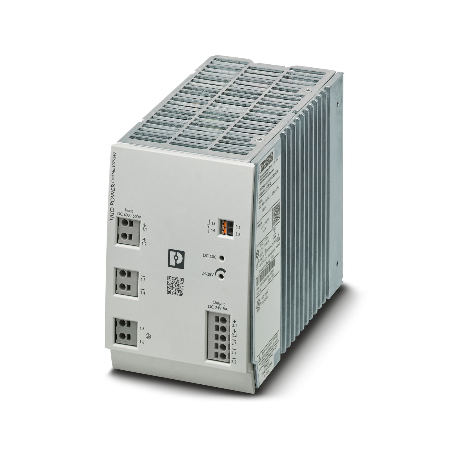
Primary-switched TRIO POWER DC/DC converter with Push-in connection for DIN rail mounting, input: 1,500 V DC, output: 24 V DC / 8 A
Product details
| DC operation | |
| Nominal input voltage range | 600 V DC ... 1500 V DC |
| Input voltage range | 600 V DC ... 1500 V DC -15 % ... +10 % |
| Wide-range input | no |
| Input voltage range DC | 600 V DC ... 1500 V DC -15 % ... +10 % |
| Electric strength, max. | ≤ 1800 V DC 1 s |
| Typical national grid voltage | 1500 V DC |
| 600 V DC | |
| Voltage type of supply voltage | DC |
| Inrush current integral (I2t) | typ. 0.15 A2s |
| Current consumption | typ. 0.35 A (600 V DC) |
| typ. 0.145 A (1500 V DC) | |
| Recommended breaker for input protection | 1 A (gPV) |
| Recommended fuse for input protection | 1500 V DC |
| Efficiency | typ. 91.5 % (600 V DC) |
| typ. 90.9 % (900 V DC) | |
| typ. 89 % (1500 V DC) | |
| Nominal output voltage | 24 V DC ±1 % |
| Setting range of the output voltage (USet) | 24 V DC ... 28 V DC (> 24 V DC, constant capacity restricted) |
| Nominal output current (IN) | 8 A |
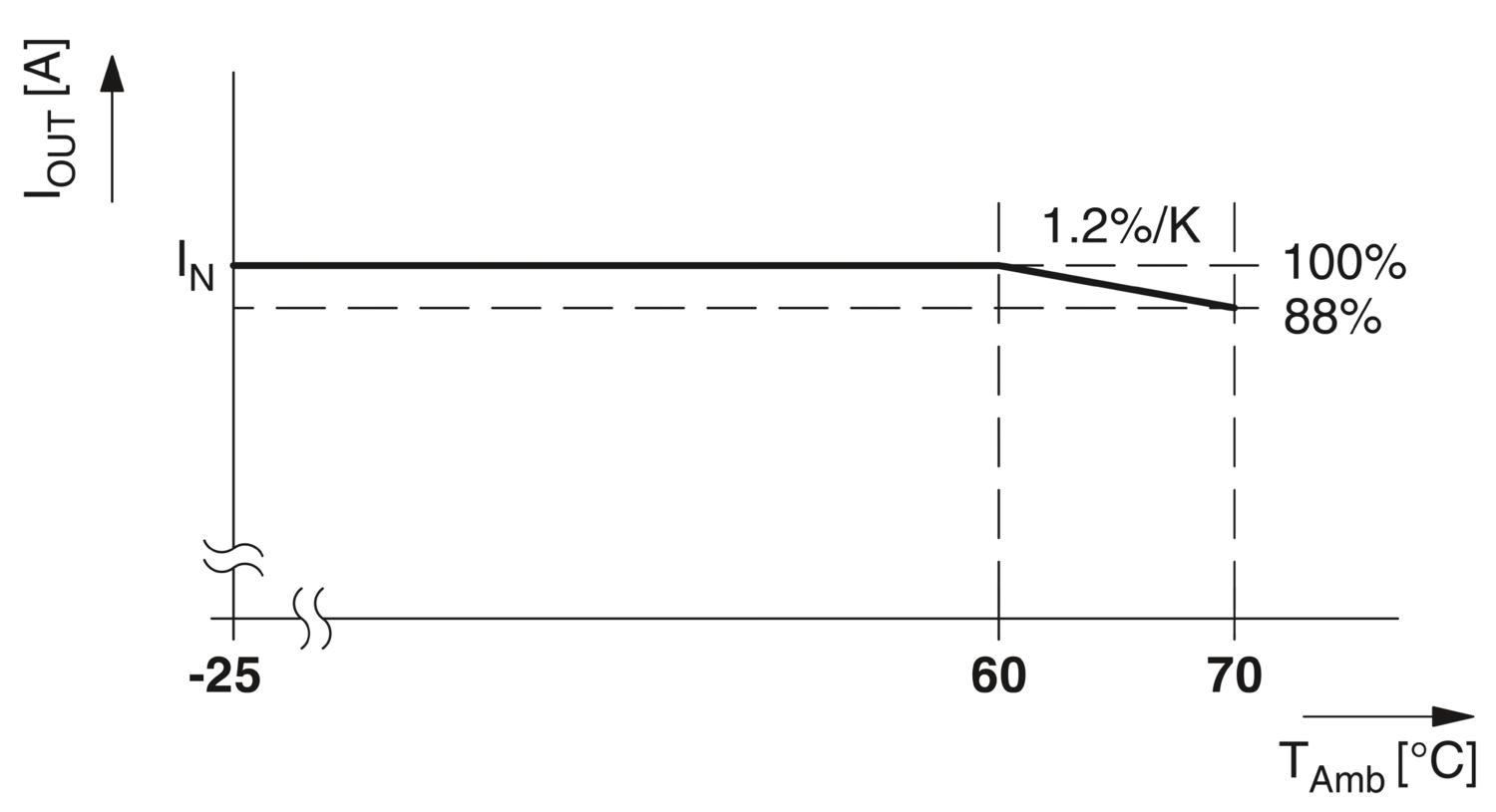
| Derating | > 60 °C ... 70 °C (2.5 %/K) |
| Feedback voltage resistance | ≤ 35 V DC |
| Protection against overvoltage at the output (OVP) | ≤ 30 V DC |
| Control deviation | < 1 % (change in load, static 10 % ... 90 %) |
| < 3 % (Dynamic load change 10 % ... 90 %, 10 Hz) | |
| < 0.1 % (change in input voltage ±10 %) | |
| Residual ripple | < 40 mVPP (Ripple) |
| < 50 mVPP (Noise) | |
| Short-circuit-proof | yes |
| No-load proof | yes |
| Output power | 192 W |
| Maximum no-load power dissipation | < 9 W |
| Power loss nominal load max. | < 24 W |
| Rise time | ≤ 30 ms (UOUT (10 % ... 90 %)) |
| Connection in parallel | yes, for redundancy and increased capacity |
| Connection in series | no |
| Fuse protection (secondary side) | electronic |
| Signal: DC OK | |
| Continuous load current | 100 mA |
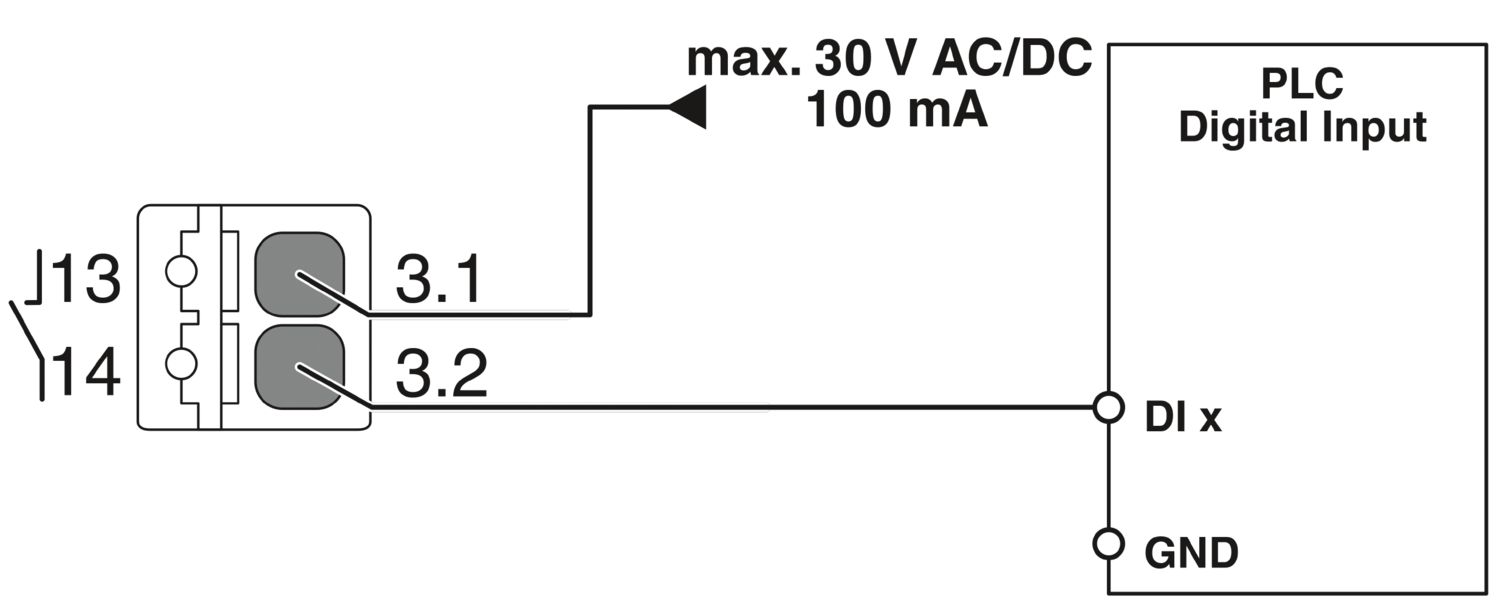
| Signal relay 13/14 | |
| Default | closed |
| Digital | 30 V AC 30 V DC 100 mA |
| Input | |
| Connection method | Push-in connection |
| Conductor cross-section, rigid min. | 1 mm² |
| Conductor cross-section, rigid max. | 4 mm² |
| Conductor cross-section flexible min. | 1 mm² |
| Conductor cross-section flexible max. | 2.5 mm² |
| Single conductor/flexible terminal point with ferrule with plastic sleeve, min. | 1 mm² |
| Single conductor/flexible terminal point with ferrule with plastic sleeve, max. | 2.5 mm² |
| Single conductor/flexible terminal point with ferrule without plastic sleeve, min. | 1 mm² |
| Single conductor/flexible terminal point with ferrule without plastic sleeve, max. | 2.5 mm² |
| Conductor cross-section AWG min. | 18 |
| Conductor cross-section AWG max. | 12 |
| Stripping length | 10 mm |
| Output | |
| Connection method | Push-in connection |
| Conductor cross-section, rigid min. | 1 mm² |
| Conductor cross-section, rigid max. | 4 mm² |
| Conductor cross-section flexible min. | 1 mm² |
| Conductor cross-section flexible max. | 2.5 mm² |
| Single conductor/flexible terminal point with ferrule with plastic sleeve, min. | 0.2 mm² |
| Single conductor/flexible terminal point with ferrule with plastic sleeve, max. | 1.5 mm² |
| Single conductor/flexible terminal point with ferrule without plastic sleeve, min. | 0.2 mm² |
| Single conductor/flexible terminal point with ferrule without plastic sleeve, max. | 1.5 mm² |
| Conductor cross-section AWG min. | 18 |
| Conductor cross-section AWG max. | 12 |
| Stripping length | 10 mm |
| Signal | |
| Connection method | Push-in connection |
| Conductor cross-section, rigid min. | 0.2 mm² |
| Conductor cross-section, rigid max. | 1.5 mm² |
| Conductor cross-section flexible min. | 0.2 mm² |
| Conductor cross-section flexible max. | 1.5 mm² |
| Single conductor/flexible terminal point with ferrule with plastic sleeve, min. | 0.2 mm² |
| Single conductor/flexible terminal point with ferrule with plastic sleeve, max. | 1.5 mm² |
| Single conductor/flexible terminal point with ferrule without plastic sleeve, min. | 0.2 mm² |
| Single conductor/flexible terminal point with ferrule without plastic sleeve, max. | 1.5 mm² |
| Conductor cross-section AWG min. | 24 |
| Conductor cross-section AWG max. | 16 |
| Stripping length | 8 mm |
| Types of signaling | LED |
| Floating signal contact | |
| Signal output: LED status indicator | |
| Signalization designation | DC OK |
| Status display | "DC OK" LED green |
| Note on status display | UOUT > 21.5 V: LED lights up |
| Color | green |
| DC OK | UOUT > 0.9 x UN (UN = 24 V DC) |
| Number of phases | 1 |
| Insulation voltage input/output | 4.2 kV DC (type test) |
| 2.6 kV DC (routine test) |
| Product family | TRIO POWER |
| MTBF (IEC 61709, SN 29500) | > 1500000 h (25 °C) |
| > 900000 h (40 °C) | |
| > 400000 h (60 °C) | |
| Insulation characteristics | |
| Protection class | I |
| Degree of pollution | 2 |
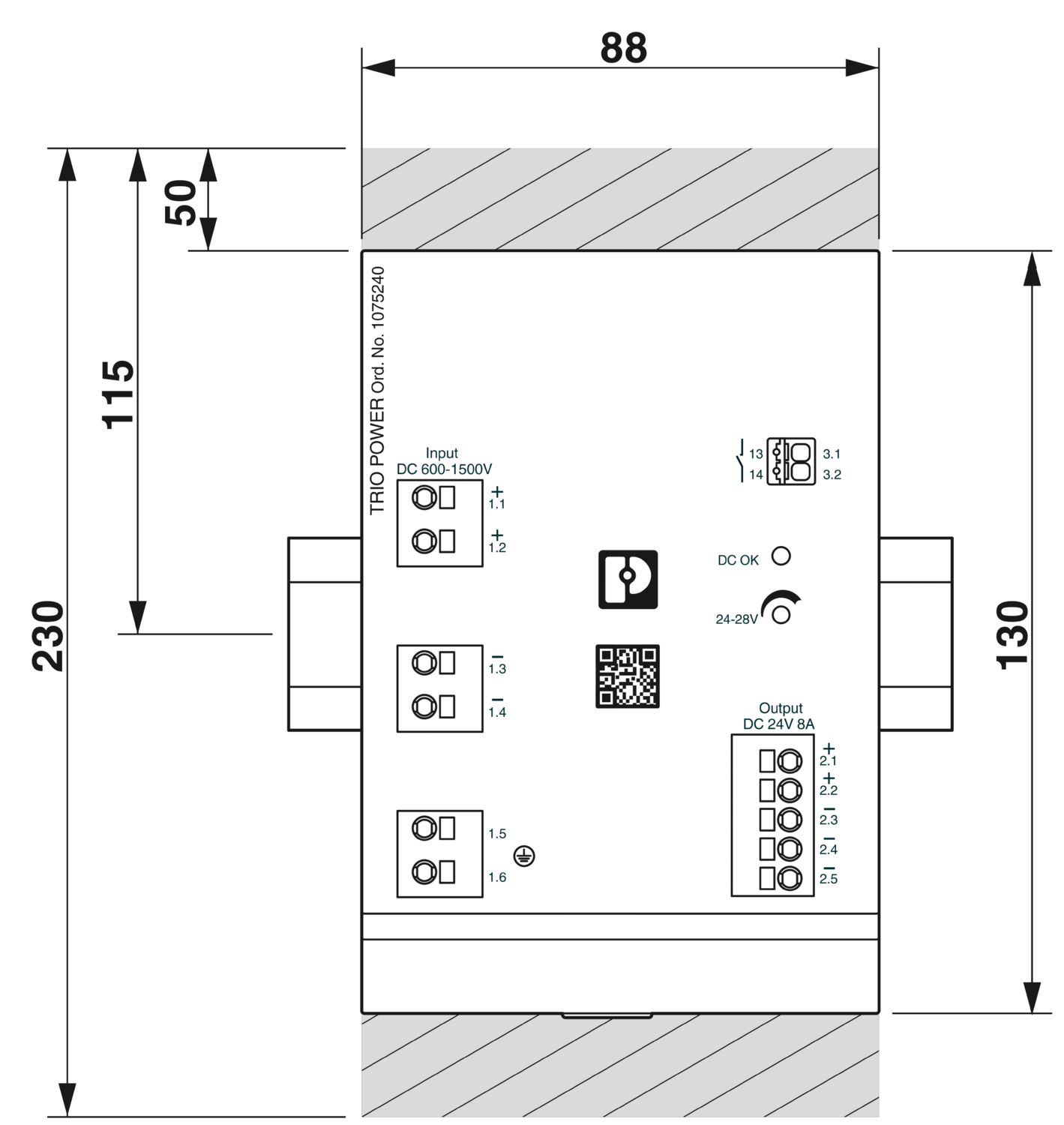
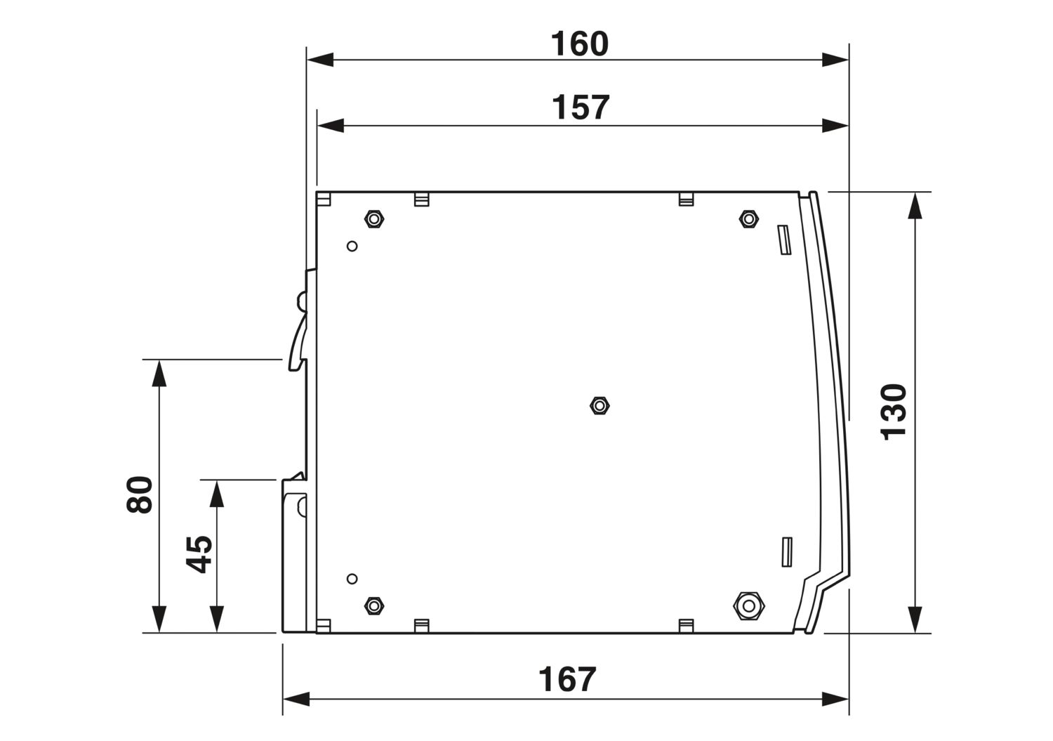
| Dimensional drawing |
|
| Width | 88.5 mm |
| Height | 130 mm |
| Depth | 160 mm |
| Installation dimensions | |
| Installation distance right/left | 0 mm / 0 mm (≤ 40°C) |
| Installation distance right/left (active) | 10 mm / 10 mm (≤ 70 °C) |
| Installation distance top/bottom | 50 mm / 50 mm (≤ 70 °C) |
| Installation distance top/bottom (active) | 50 mm / 50 mm (≤ 70 °C) |
| Mounting type | DIN rail mounting |
| Assembly note | alignable: horizontally 0 mm (≤ 40 °C) 10 mm (≤ 70 °C), vertically 50 mm |
| Mounting position | horizontal DIN rail NS 35, EN 60715 |
| With protective coating | no |
| Flammability rating according to UL 94 (housing / terminal blocks) | V0 |
| Housing material | Metal |
| Type of housing | Aluminum (AlMg3) |
| Hood version | Polycarbonate |
| Ambient conditions | |
| Degree of protection | IP20 |
| Ambient temperature (operation) | -25 °C ... 70 °C (>60°C derating: 1.2%/K) |
| Ambient temperature (storage/transport) | -40 °C ... 85 °C |
| Ambient temperature (start-up type tested) | -40 °C |
| Maximum altitude | ≤ 4000 m (> 2000 m, Derating: 10 %/1000 m) |
| Climatic class | 3K3 (in acc. with EN 60721) |
| Max. permissible relative humidity (operation) | ≤ 95 % (at 25 °C, non-condensing) |
| Shock | 18 ms, 30g, in each space direction (according to IEC 60068-2-27) |
| Vibration (operation) | < 15 Hz, amplitude ±2.5 mm (according to IEC 60068-2-6) |
| 15 Hz ... 150 Hz, 2.3g, 90 min. | |
| Standard - Electrical safety | EN 62109-1:2011 |
| Standard – Safety extra-low voltage | IEC 62109-1:2011 (SELV) |
| Standard - Safe isolation | DIN VDE 0100-410 |
| Overvoltage category | |
| IEC 62109-1 | II |
| UL approvals | UL 62109-1:2014 |
| Electromagnetic compatibility | Conformance with EMC Directive 2014/30/EU |
| Low Voltage Directive | Conformance with Low Voltage Directive 2014/35/EC |
| Noise immunity | EN 61000-6-2:2005 |
| Conducted noise emission | |
| Standards/regulations | EN 55016 |
| EN 61000-6-4 (Class A) | |
| Noise emission | |
| Standards/regulations | EN 55016 |
| EN 61000-6-4 (Class A) | |
| Electrostatic discharge | |
| Standards/regulations | EN 61000-4-2 |
| Electrostatic discharge | |
| Contact discharge | 4 kV (Test Level 2) |
| Discharge in air | 8 kV (Test Level 3) |
| Comments | Criterion A |
| Electromagnetic HF field | |
| Standards/regulations | EN 61000-4-3 |
| Electromagnetic HF field | |
| Frequency range | 80 MHz ... 1 GHz |
| Test field strength | 20 V/m (> Test intensity 3) |
| Frequency range | 1 GHz ... 2 GHz |
| Test field strength | 10 V/m (Test Level 3) |
| Frequency range | 2 GHz ... 3 GHz |
| Test field strength | 10 V/m (Test Level 3) |
| Comments | Criterion A |
| Fast transients (burst) | |
| Standards/regulations | EN 61000-4-4 |
| Fast transients (burst) | |
| Input | 4 kV (Test Level 4 - asymmetrical) |
| Output | 2 kV (Test Level 3 - asymmetrical) |
| Signal | 1 kV (Test Level 3 - asymmetrical) |
| Comments | Criterion B |
| Surge voltage load (surge) | |
| Standards/regulations | EN 61000-4-5 |
| Surge voltage load (surge) | |
| Input | 3 kV (Test intensity >4 - symmetrical) |
| 6 kV (Test intensity >4 - asymmetrical) | |
| Output | 1 kV (Test Level 3 - symmetrical) |
| 2 kV (Test Level 3 - asymmetrical) | |
| Signal | 1 kV (Test Level 3 - symmetrical) |
| 2 kV (Test Level 3 - asymmetrical) | |
| Comments | Criterion B |
| Conducted interference | |
| Standards/regulations | EN 61000-4-6 |
| Conducted interference | |
| Input/Output | asymmetrical |
| Frequency range | 0.15 MHz ... 80 MHz |
| Comments | Criterion A |
| Voltage | 10 V (Test Level 3) |
| Voltage dips | |
| Standards/regulations | EN 61000-4-11 |
| Emitted interference | |
| Standards/regulations | EN 61000-6-4 |
| Radio interference voltage in acc. with EN 55011 | EN 55011 (EN 55022) Class A industrial area of application |
| Emitted radio interference in acc. with EN 55011 | EN 55011 (EN 55022) Class A industrial area of application |
| Criteria | |
| Criterion A | Normal operating behavior within the specified limits. |
| Criterion B | Temporary impairment to operational behavior that is corrected by the device itself. |
UL Recognized
Approval ID: FILE E 476951IECEE CB Scheme
Approval ID: US-33734-ULEAC
Approval ID: RU S-DE.BL08.W.00764
Your advantages
Suitable for use in all photovoltaic systems with high input voltage due to conformity with standards UL 62109 and UL 1741
High system availability with a robust design that ensures partial discharge resistance
Direct, immediate supply from the solar field to supply the string monitoring function within string combiner boxes
Quick and easy installation with Push-in connection