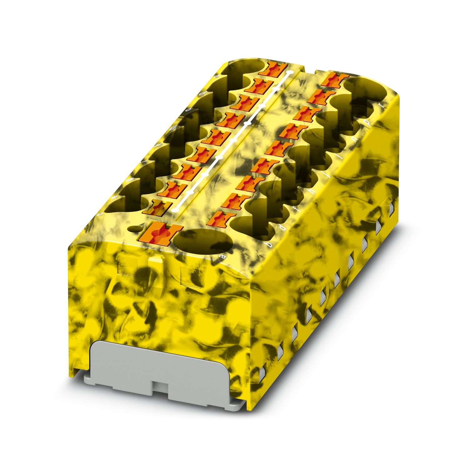
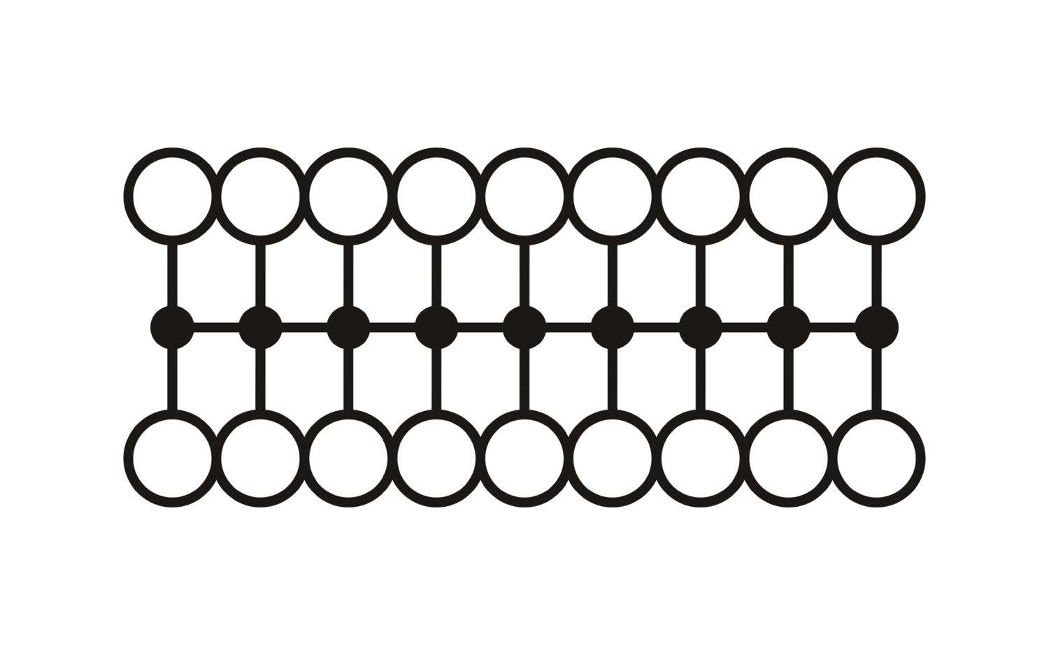
For power distribution applications, IEC 60364-4-43.2008; modified + corrigendum Okt. 2008 (DIN VDE 0100-430:2010-10) section 433.2 ff must be observed!
Product type
Distributor terminal block
Number of connections
19
Number of rows
1
Potentials
1
Insulation characteristics
Overvoltage category
III
Degree of pollution
3
Rated surge voltage
6 kV
Maximum power dissipation for nominal condition
1.02 W
Service Entrance
yes
Number of connections per level
19
Nominal cross section
4 mm²
Rated cross section AWG
12
Load contact
Connection method
Push-in connection
Stripping length
10 mm ... 12 mm
Internal cylindrical gage
A4
Connection in acc. with standard
IEC 60998-2-2
Conductor cross-section rigid
0.2 mm² ... 6 mm²
Cross section AWG
24 ... 10 (converted acc. to IEC)
Conductor cross-section flexible
0.2 mm² ... 6 mm²
Conductor cross-section, flexible [AWG]
24 ... 10 (converted acc. to IEC)
Conductor cross-section flexible (ferrule without plastic sleeve)
0.2 mm² ... 4 mm²
Flexible conductor cross-section (ferrule with plastic sleeve)
0.2 mm² ... 4 mm²
2 conductors with the same cross section, flexible, with TWIN ferrule with plastic sleeve
0.5 mm² ... 1 mm²
Nominal cross section
4 mm²
Nominal current
32 A
Maximum load current
41 A (with 6 mm² conductor connection)
Maximum total current
63 A (The maximum load current of the individual terminal point must not be exceeded.)
Nominal voltage
450 V
Line contact
Connection method
Push-in connection
Stripping length
12 mm ... 14 mm
Connection in acc. with standard
IEC 60998-2-2
Conductor cross-section rigid
0.5 mm² ... 10 mm²
Cross section AWG
24 ... 10 (converted acc. to IEC)
Conductor cross-section flexible
0.5 mm² ... 10 mm²
Conductor cross-section, flexible [AWG]
24 ... 10 (converted acc. to IEC)
Conductor cross-section flexible (ferrule without plastic sleeve)
0.5 mm² ... 10 mm²
Flexible conductor cross-section (ferrule with plastic sleeve)
0.5 mm² ... 10 mm²
2 conductors with the same cross section, flexible, with TWIN ferrule with plastic sleeve
0.75 mm² ... 2.5 mm²
Nominal cross section
10 mm²
Nominal current
57 A
Maximum load current
57 A (with 10 mm² conductor cross-section)
Maximum total current
63 A (The maximum load current of the individual terminal point must not be exceeded.)
Conductor cross-section flexible (ferrule without plastic sleeve)
0.75 mm² ... 4 mm²
Flexible conductor cross-section (ferrule with plastic sleeve)
0.5 mm² ... 4 mm²
Line contact Connection cross sections directly pluggable
Conductor cross-section rigid
1.5 mm² ... 10 mm²
Conductor cross-section flexible (ferrule without plastic sleeve)
2.5 mm² ... 10 mm²
Flexible conductor cross-section (ferrule with plastic sleeve)
1.5 mm² ... 10 mm²
Width
64.8 mm
Height
28.6 mm
Depth
21.7 mm
Color
multicolored (RAL -)
black (RAL 9005)
yellow (RAL 1018)
Flammability rating according to UL 94
V0
Insulating material group
I
Insulating material
PA
Static insulating material application in cold
-60 °C
Relative insulation material temperature index (Elec., UL 746 B)
130 °C
Fire protection for rail vehicles (DIN EN 45545-2) R22
HL 1 - HL 3
Fire protection for rail vehicles (DIN EN 45545-2) R23
HL 1 - HL 3
Fire protection for rail vehicles (DIN EN 45545-2) R24
HL 1 - HL 3
Fire protection for rail vehicles (DIN EN 45545-2) R26
HL 1 - HL 3
Surface flammability NFPA 130 (ASTM E 162)
passed
Specific optical density of smoke NFPA 130 (ASTM E 662)
passed
Smoke gas toxicity NFPA 130 (SMP 800C)
passed
Mechanical data
Open side panel
No
Attachment on the carrier
Result
Test passed
Note
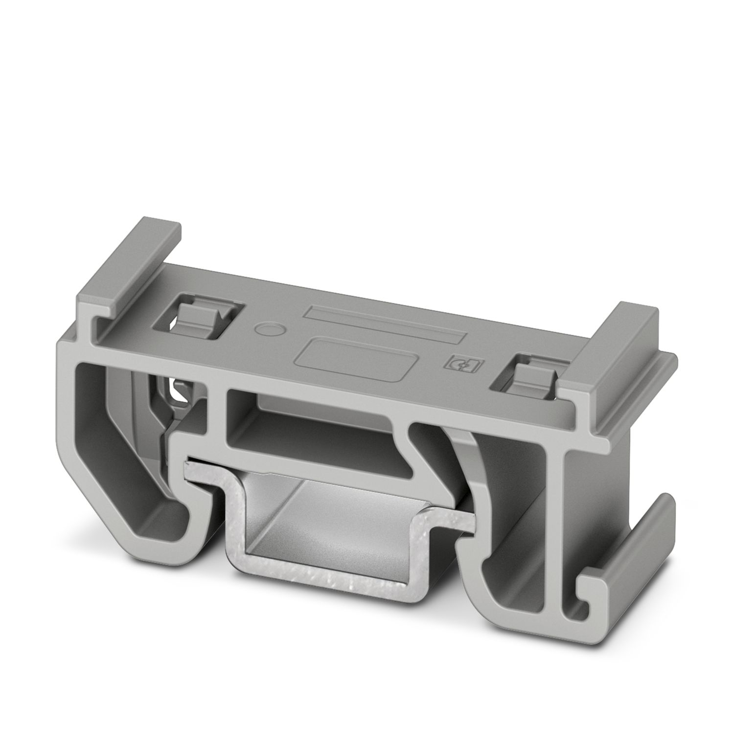
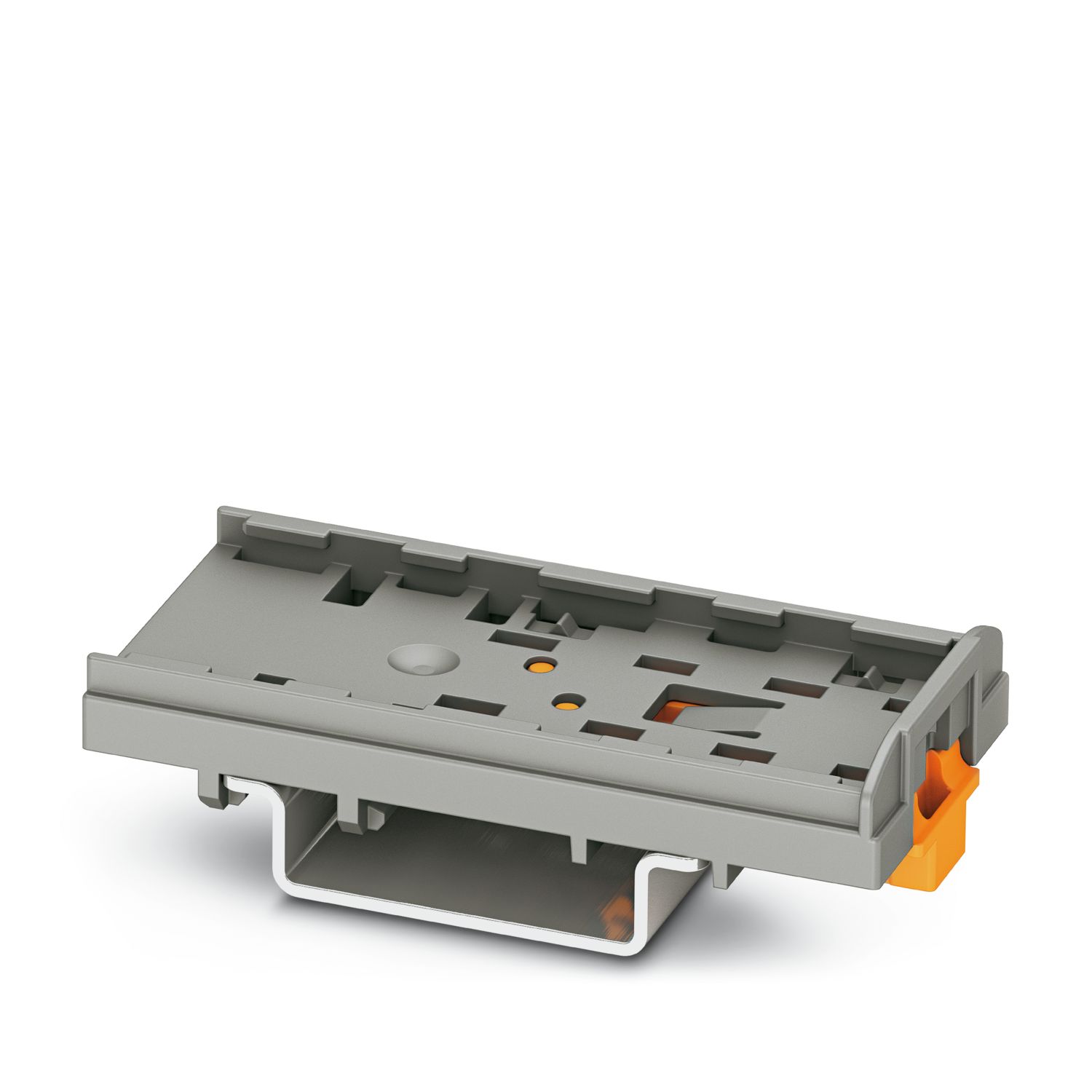
When aligning several blocks, it is recommended to either place a DIN rail adapter underneath the connection point or a flange element between the blocks.
For versions with 6 or 7 connections, it is enough to place one DIN rail adapter centrally per block and place flange elements after every other block.
When using the DIN rail adapter PTFIX-NS35, an aligned block must not protrude by more than a half.
Needle-flame test
Time of exposure
30 s
Result
Test passed
Oscillation/broadband noise
Specification
DIN EN 50155 (VDE 0115-200):2018-05
Spectrum
Long life test category 2, bogie-mounted
Frequency
f1 = 5 Hz to f2 = 250 Hz
ASD level
6.12 (m/s²)²/Hz
Acceleration
3.12g
Test duration per axis
5 h
Test directions
X-, Y- and Z-axis
Result
Test passed
Shocks
Specification
DIN EN 50155 (VDE 0115-200):2018-05
Pulse shape
Half-sine
Acceleration
30g
Shock duration
18 ms
Number of shocks per direction
3
Test directions
X-, Y- and Z-axis (pos. and neg.)
Result
Test passed
Ambient conditions
Ambient temperature (operation)
-60 °C ... 110 °C (Operating temperature range incl. self-heating; for max. short-term operating temperature, see RTI Elec.)
Ambient temperature (storage/transport)
-25 °C ... 60 °C (for a short time, not exceeding 24 h, -60 °C to +70 °C)