


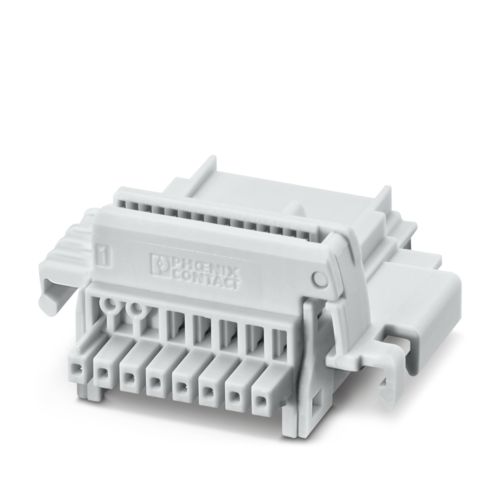
Connect individual ICS housings together easily. 8-position TBUS 8 DIN rail connectors with serial and parallel contacts enable easy module-to-module communication in the control cabinet.


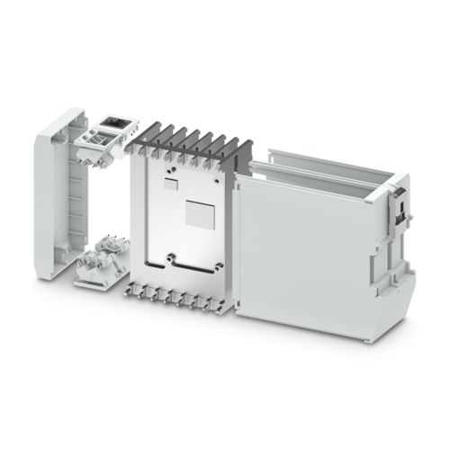
The solutions made possible by the ICS modular housing system are as varied as the requirements for future-oriented automation devices. Benefit from a housing system with graduated sizes, variable connection technology, and optional DIN rail connectors.
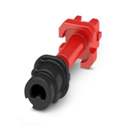
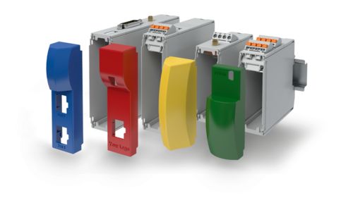
Coding profile for ICC connectors of the ICS housing series
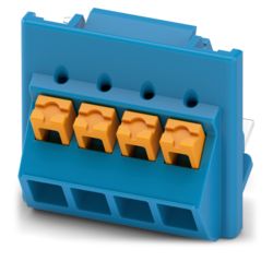
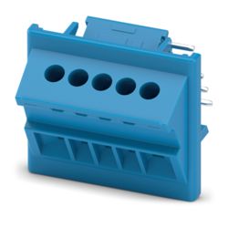
Printed circuit board terminal, nominal current: 18 A, rated voltage (III/2): 300 V, nominal cross section: 2.5 mm2, number of potentials: 4, number of rows: 1, number of positions per row: 4, product range: ICC..-TP2,5/..L5,0, pitch: 5 mm, connection method: Push-in spring connection, mounting: Wave soldering, conductor/PCB connection direction: 0 °, color: blue, Pin layout: Linear pinning, Solder pin [P]: 3.15 mm, number of solder pins per potential: 1, type of packaging: packed in cardboard. Product with pin output on left side
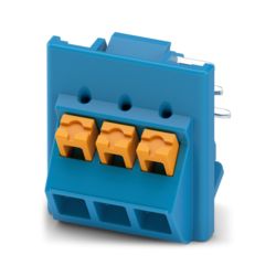
Printed circuit board terminal, nominal current: 18 A, rated voltage (III/2): 300 V, nominal cross section: 2.5 mm2, number of potentials: 3, number of rows: 1, number of positions per row: 3, product range: ICC..-TP2,5/..R5,0, pitch: 5 mm, connection method: Push-in spring connection, mounting: Wave soldering, conductor/PCB connection direction: 0 °, color: blue, Pin layout: Linear pinning, Solder pin [P]: 3.15 mm, number of solder pins per potential: 1, type of packaging: packed in cardboard. Product with pin output on right side
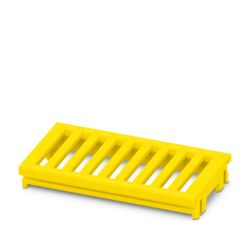
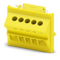
DIN rail housing, ICS filler, with vents, width: 25 mm, height: 7.25 mm, depth: 44.9 mm, color: yellow (similar RAL 1018)
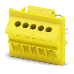
Printed circuit board terminal, nominal current: 16 A, rated voltage (III/2): 150 V, nominal cross section: 1.5 mm2, number of potentials: 5, number of rows: 1, number of positions per row: 5, product range: ICC..-TS1,5/..L3,5, pitch: 3.5 mm, connection method: Screw connection with tension sleeve, screw head form: L Slotted, mounting: Wave soldering, conductor/PCB connection direction: 0 °, color: yellow, Pin layout: Linear pinning, Solder pin [P]: 2.8 mm, number of solder pins per potential: 1, type of packaging: packed in cardboard. Product with pin output on left side
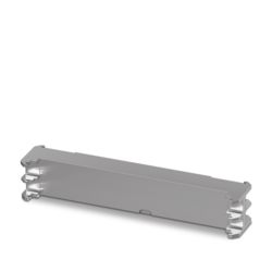
Heatsink for housing series: ICS, material: Aluminum, anodized, product range: ICS25-..122X.., width: 22.4 mm, height: 25 mm, Individual milling possible.
Printed circuit board terminal, nominal current: 16 A, rated voltage (III/2): 150 V, nominal cross section: 1.5 mm2, number of potentials: 5, number of rows: 1, number of positions per row: 5, product range: ICC..-TS1,5/..R3,5, pitch: 3.5 mm, connection method: Screw connection with tension sleeve, screw head form: L Slotted, mounting: Wave soldering, conductor/PCB connection direction: 0 °, color: yellow, Pin layout: Linear pinning, Solder pin [P]: 2.8 mm, number of solder pins per potential: 1, type of packaging: packed in cardboard. Product with pin output on right side
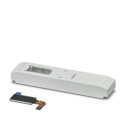
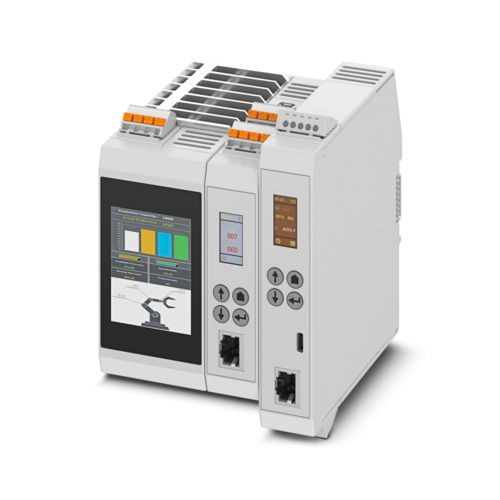
DIN rail housing, Upper part, integrated 0.96″ display, resolution: 80 x 160 Pixel(s), interface: 4-wire SPI half duplex, Housing cover, width: 25 mm, height: 122 mm
Printed circuit board terminal, nominal current: 16 A, rated voltage (III/2): 150 V, nominal cross section: 1.5 mm2, number of potentials: 5, number of rows: 1, number of positions per row: 5, product range: ICC..-TS1,5/..R3,5, pitch: 3.5 mm, connection method: Screw connection with tension sleeve, screw head form: L Slotted, mounting: Wave soldering, conductor/PCB connection direction: 0 °, color: blue, Pin layout: Linear pinning, Solder pin [P]: 2.8 mm, number of solder pins per potential: 1, type of packaging: packed in cardboard. Product with pin output on right side
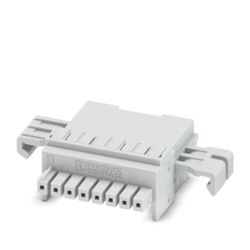
DIN rail bus adapter for ICS, overall width: 20 mm, 8 parallel positions, color: light gray (similar to RAL 7035)

The 50 mm wide lower housing part provides the largest possible PCB surface in the ICS series and thus creates more space for the electronics it holds. In total, up to four PCBs and 20 connectors with up to 100 positions can be mounted in the housing.

Configure your ICS housing. Choose from Push-in and screw connection technologies. Antenna, USB, or RJ45 connections can be easily integrated with additional accessories. Prepared displays, keypads, and heatsinks enable you to create sophisticated applications. You can also use the PROTIQ 3D printing service for prototype production of your housing cover. Once the configuration has been completed, you can use the online thermal simulation and get your design into series production.

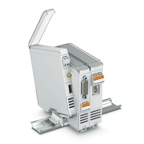
Benefit from a comprehensive selection of modules and a high degree of flexibility in connection technology for IoT applications: Standardized connection technology such as RJ45, USB, and D-SUB connections can be used in a modular way for ICS series DIN rail housings. The 8-pos. TBUS also makes module-to-module communication easier.


Connect individual ICS housings together easily. 8-position TBUS 8 DIN rail connectors with serial and parallel contacts enable easy module-to-module communication in the control cabinet.

The ICS series for the DIN rail features modular connection technology for RJ45, D-SUB, USB, and antenna connections that is unique on the market. PCB headers enable plug-in connection technology of the ICS housing series. Connectors with screw or Push-in technology, with 3 and 4 positions with 5.0 mm pitch increase their flexibility.

The modular system of the ICS housing provides a high level of scalability, tailor-made for your requirements. Overall widths of 20 mm, 25 mm, and 50 mm, installed heights of 77.5 mm, 100 mm, and 122.5 mm, and installed depths of 87.5 mm, 110 mm, and 132.5 mm are available.

Because of its flexibility, the ICS housing enables technically complex solutions to be implemented in a confined space in the control cabinet. Make ideal use of the space for up to two PCBs with a width of 25 mm and for up to four PCBs with a width 50 mm – with an installation time of just a few seconds. This gives you more space and area for relays and electrolytic capacitors. The design, colors, and printing can be tailored.

The visualization and adjustment of processes and characteristic values at the touch of a finger are becoming increasingly important. Touch displays and high-resolution displays with membrane keypads enrich the equipment of the ICS series modular system.

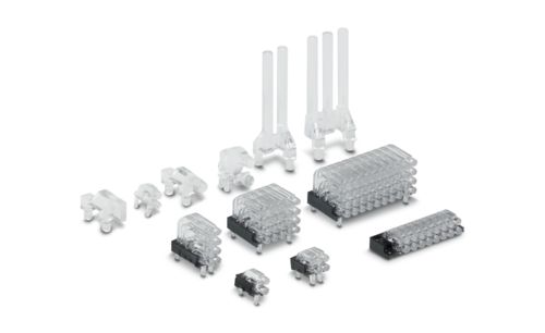
Light guides are available in various designs for status and diagnostic indicators. Mounting is simple thanks to press pins. On request, the fiber-optic cables can be supplied matched to your DIN rail housing.
2.4" touch displays and 0.96" displays with configurable membrane keypads round out the ICS series electronics housings portfolio.
Discover the high level of operating convenience offered by the ICS housings in the adjacent 3D view.
Passive heatsinks allow the devices to be used even in thermally demanding applications. Extensive thermal simulations help achieve the optimum arrangement of components on the printed circuit board.

Use the strengths of two housing families for your application: The two product families ME-IO and ICS can be combined flexibly with each other via T-BUS DIN rail connectors – in whichever way your application requires.


