Application Settings and Defaults
 This is a backstage feature.
You can make the following basic settings in the Options section of the backstage area:
Common
Set the application language.
Project settings
Specify the default project settings and create and edit project templates based on the default settings.
| Further Info
See the topic "Project Templates" for details on creating and using templates. |
The following settings can be used as default settings for new projects and for project templates:
| Settings | Description | |
|---|---|---|
| Din rail | ||
| Default | Define the default mounting rail that is inserted into the workspace when clicking the HOME > INSERT | Endless mounting rail button.
|
|
| Length of rail | Specify the default length of standard mounting rails to be used when inserting into the workspace. | |
| Zero cut offset | Define a zero cut for perforated rails.In the default setting (value 0), the zero cut is in the middle of the first elongated hole. The zero cut is changed accordingly by entering a value in the input field. The value may only be positive and may not exceed the sum of the hole length and hole spacing. | |
| Mounting space / Width of mounting space | Set the Mounting space toggle button to 'ON' to enable the use of the mounting space on the left and right of the mounting rail and enter the desired space at both ends (the space is blocked for the fixing of the rail). | |
| Terminal strip | Define the default end bracket that is used for the autocorrection function and for placing the terminal strip into the workspace when clicking the HOME > INSERT | Terminal strip button, the marker carrier and label used by default.
|
|
| Marking | Define the default material type that is used for marking elements and the default font type, font size and rotation used for marking labels.
|
|
| Gap between items | Specify the default gap between individual terminals placed on mounting rails.
|
|
| Machine-assembled items | When you set the toggle buttons to 'ON', machine-assembled items can be placed. CLM and CLXM articles already have a marking label implemented, so they can be labeled directly as an entire terminal strip using a laser. | |
When you modify any of the values in this page, the Save & Apply button appears on the bottom right of the page. By clicking this button, the settings are saved and applied to the currently opened project.
| Note
With the exception of the Gap between items value (see above), all other settings are applied only to items that are newly inserted when you click Save & Apply. Elements already inserted are not affected. |
Interface settings
- Set up the interfaces for interaction with other CAE applications.
- Define how marking information is to be exported:
-
By block: The marking information when creating a klm export is output sequentially per terminal strip and based on the marking positions of the terminal blocks.
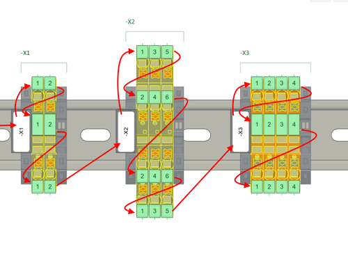
-
By DIN rail: With this export, the labeling information is exported continuously from the beginning to the end of the DIN rail and based on the marking positions of the terminal blocks.

-
By block: The marking information when creating a klm export is output sequentially per terminal strip and based on the marking positions of the terminal blocks.