User Interface
This topic contains the following sections:
- Start page – quick access to the most important functions
- Backstage area – for application settings and default values
- Engineering view – do the planning
Start page – quick access to the most important functions
The start page appears each time you start cxE. It provides quick access to application functions that you might find useful to start your work:
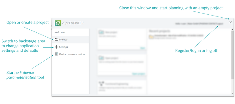
| Further Info
Start and save a project Application settings and defaults Engineering assistants and configurators |
Backstage area – for application settings and default values
 Clicking the cxE icon on the left opens the backstage area.
Besides the "usual" functions like opening/creating or saving projects and information, this is where you...
- ... make the basic application settings like language, set default values and set up the interfaces to external applications.
- ... find the project history and roll back the project to specific project versions or history points.
- ... create and download/copy the project documentation (including part lists) for follow-on usage or data archiving.
- ... find detailed version information on the application itself and the technical components used.
- ... open the cxE online help from the About section.
Note
 A yellow dot on the backstage area icon indicates that there are new cxE release notes available for download in the About section (the dot is also shown next to the Release notes entry in the About section). The icon is removed once you have opened the Release notes link in the About section. A yellow dot on the backstage area icon indicates that there are new cxE release notes available for download in the About section (the dot is also shown next to the Release notes entry in the About section). The icon is removed once you have opened the Release notes link in the About section. |
Engineering view – do the planning
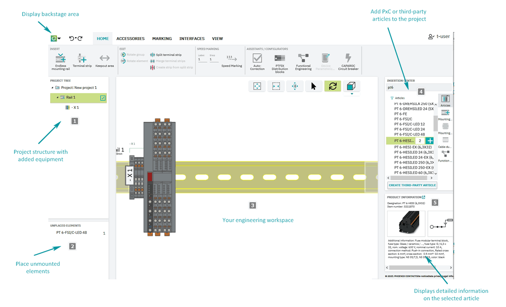
The actual application UI, where you do the planning, consists of a fix central editing area (the engineering workspace) and additional windows for specific purposes, which you can displayed/hide and resize according to your needs.
The following picture shows the different areas of the UI and gives you a general idea of their functions.
| Note
The arrangement of the views and windows has been optimized for engineering tasks and cannot be changed. You can, however, resize the individual windows and toggle their display on the VIEW tab. |
| Note
In this documentation, we use the following notation and style to refer to individual commands (buttons) in the toolbar ribbon: tab name > ribbon heading | button on the ribbon Example: ACCESSORIES > INSERT | |
| (1) | The PROJECT TREE
on the left shows the mounting devices contained in the project together with the mounted equipment (terminal strips).
 Read more... Read more...
|
|
| (2) | The UNPLACED ELEMENTS window is used to handle components and articles that are not placed on mounting rails, mounting panels or enclosures in the current project. You can use this container as a clipboard for the articles and components to be put on purpose. All articles and components added to the UNPLACED ELEMENTS window are not contained in the order.Display/hide this window: VIEW > WINDOW | Unplaced Elements
|
|
| (3) | The WORKSPACE in the middle is the actual editing area where you do the engineering. It shows the 3D representation of the mounting devices that are selected for display in the project tree. The workspace is always visible.With the buttons for the image display settings (in the upper right corner), you can adapt the display of the configuration image according to your needs. 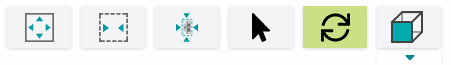
|
|
| (4) | The INSERTION CENTER is the central access to all Phoenix Contact mounting devices, articles and accessories that are available for you. If you need to insert a custom (3rd party) article, you can create and insert this article from the Insertion Center, too.Display/hide this window: VIEW > WINDOW | Insertion Center
|
|
| (5) | The PRODUCT INFORMATION window displays an image and general information on the item that is currently selected in the workspace or the insertion center.Display/hide this window: VIEW > WINDOW | Product information |