The terminal is designed for use within an Inline station. It is used to output digital signals. Thanks to special engineering measures and tests, the terminal can be used under extreme ambient conditions.

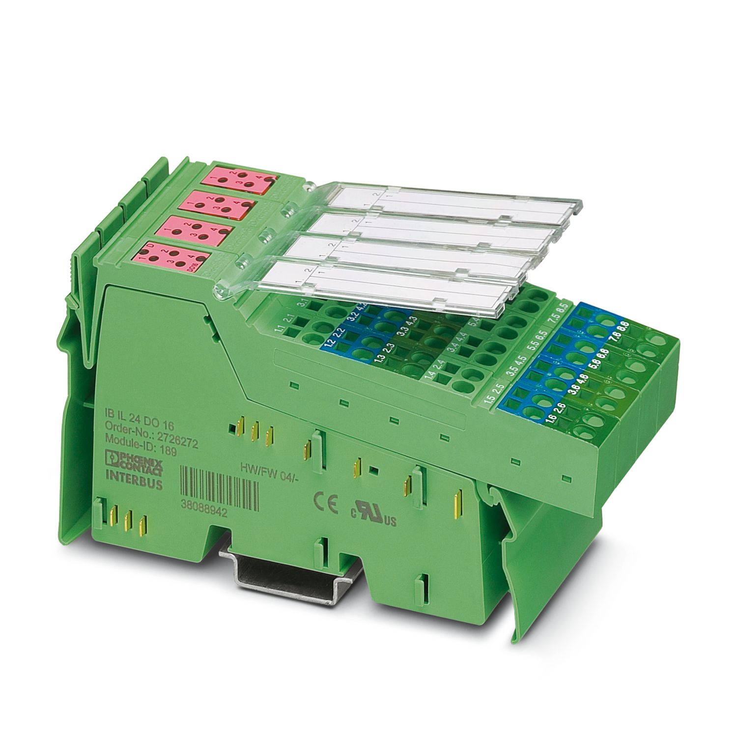
Inline, Digital output terminal, Digital outputs: 16, 24 V DC, 500 mA, connection technology: 3-conductor, Extreme conditions version, transmission speed in the local bus: 500 kbps, degree of protection: IP20, including Inline connectors and marking fields
The terminal is designed for use within an Inline station. It is used to output digital signals. Thanks to special engineering measures and tests, the terminal can be used under extreme ambient conditions.
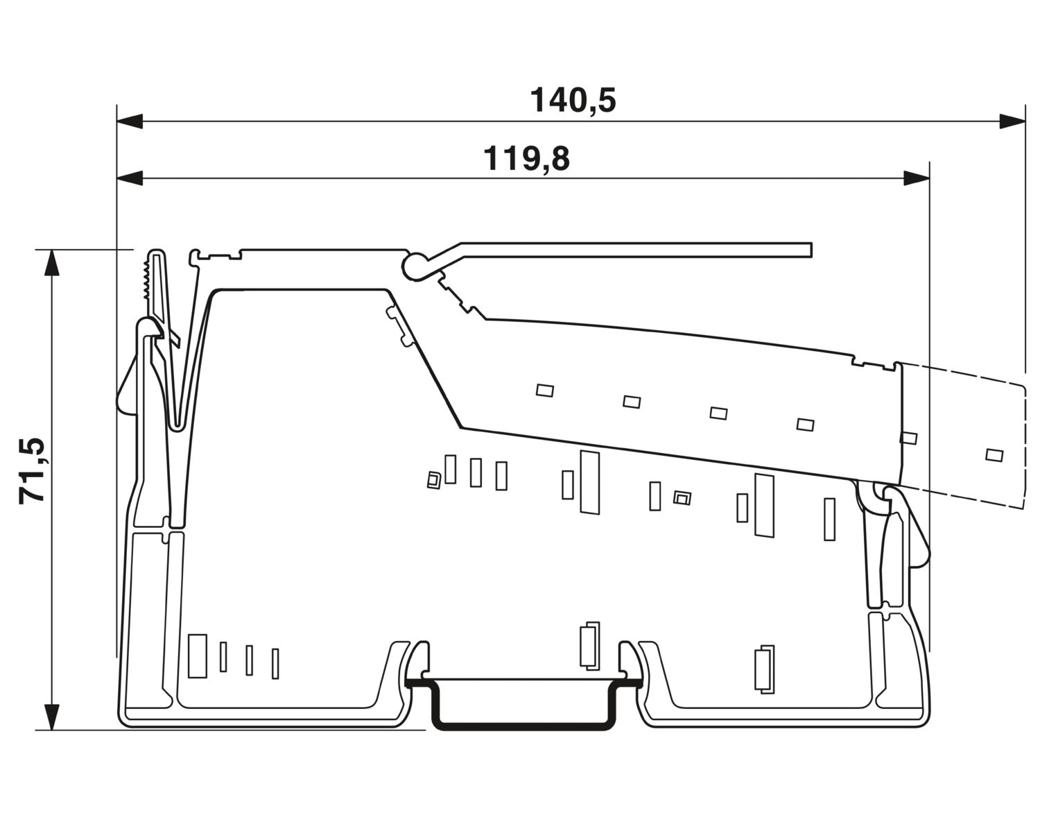
| Dimensional drawing |
|
| Width | 48.8 mm |
| Height | 140.5 mm |
| Depth | 71.5 mm |
| Note on dimensions | Housing dimensions |
| Note on application | |
| Note on application | Only for industrial use |
| Inline local bus | |
| Number of interfaces | 2 |
| Connection method | Inline data jumper |
| Transmission speed | 500 kbps |
| Module | |
| ID code (dec.) | 189 |
| ID code (hex) | BD |
| Length code (hex) | 01 |
| Length code (dec) | 01 |
| Process data channel | 16 bit |
| Input address area | 0 Byte |
| Output address area | 2 Byte |
| Register length | 16 bit |
| Required parameter data | 4 Byte |
| Required configuration data | 4 Byte |
| Digital: | |
| Output name | Digital outputs |
| Connection method | Spring-cage connection |
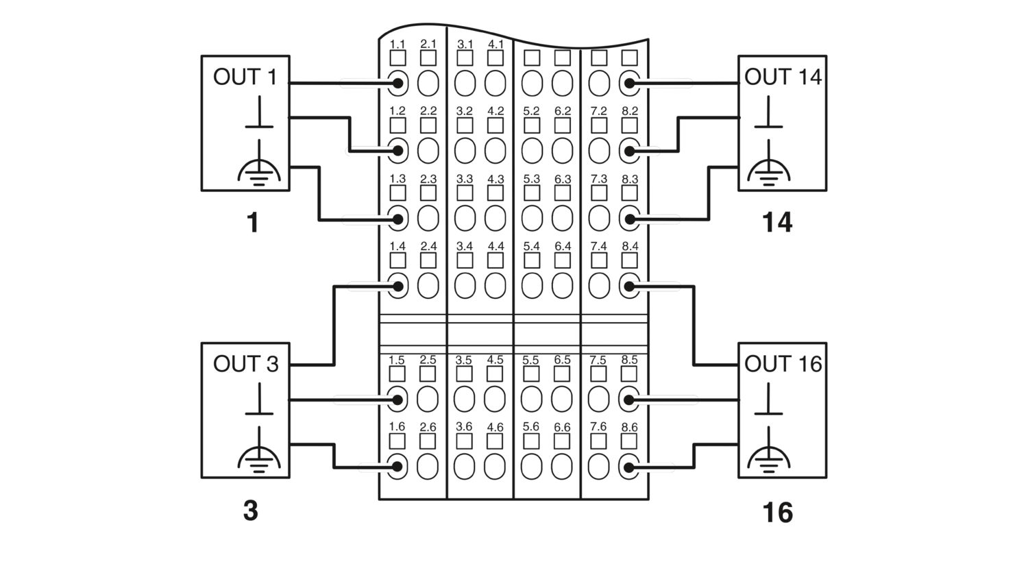
| Connection technology | 3-conductor |
| Number of outputs | 16 |
| Protective circuit | Overload protection, short-circuit protection of outputs; electronic |
| Output voltage | 24 V DC (US - 1 V) |
| Limitation of the voltage induced on circuit interruption | -46 V ... -15 V |
| Maximum inrush current | max. 1.5 A (for 20 ms) |
| Output current | max. 500 mA (per channel) |
| max. 8 A (Device) | |
| Nominal output voltage | 24 V DC |
| Output voltage when switched off | max. 2 V |
| Output current when switched off | max. 300 µA |
| Nominal load, inductive | 12 VA (1.2 H, 50 Ω) |
| Nominal load, lamp | 12 W |
| Nominal load, ohmic | 12 W (48 Ω) |
| Maximum operating frequency with ohmic nominal load | max. 300 Hz (this switching frequency is limited by the number of bus devices, the structure of the bus, the software used and the control or computer system used) |
| Reverse voltage resistance to short pulses | Reverse voltage proof |
| Behavior with overload | Auto restart |
| Behavior with inductive overload | Output can be destroyed |
| Behavior at voltage switch-off | The output follows the power supply without delay |
| Overcurrent shut-down | min. 0.7 A |
| Output current with ground connection interrupt when switched off | max. 25 mA |
| Product type | I/O component |
| Product family | Inline |
| Type | modular |
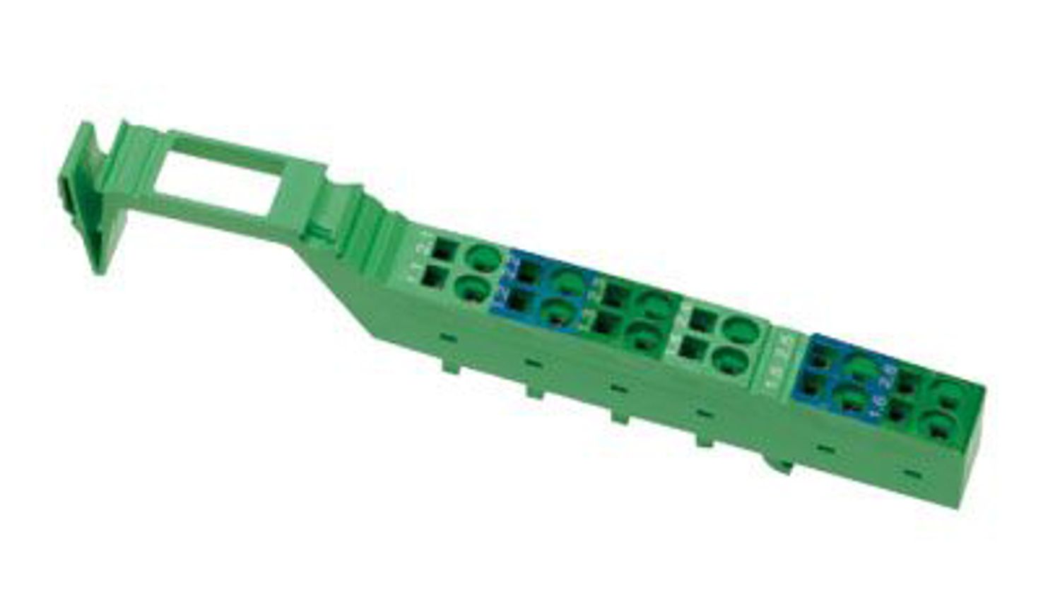
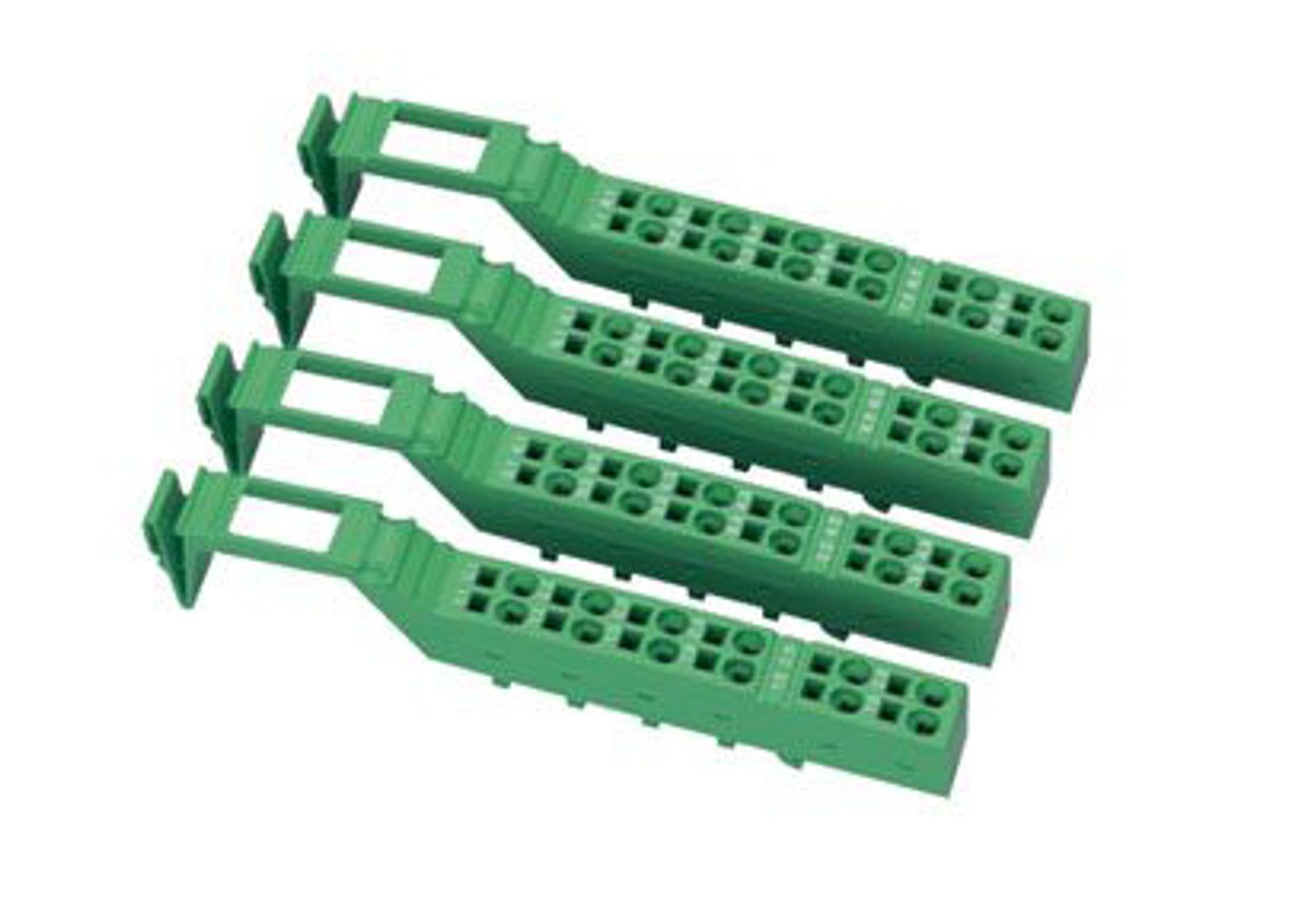
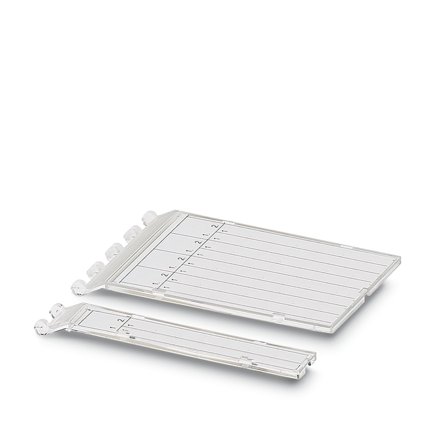
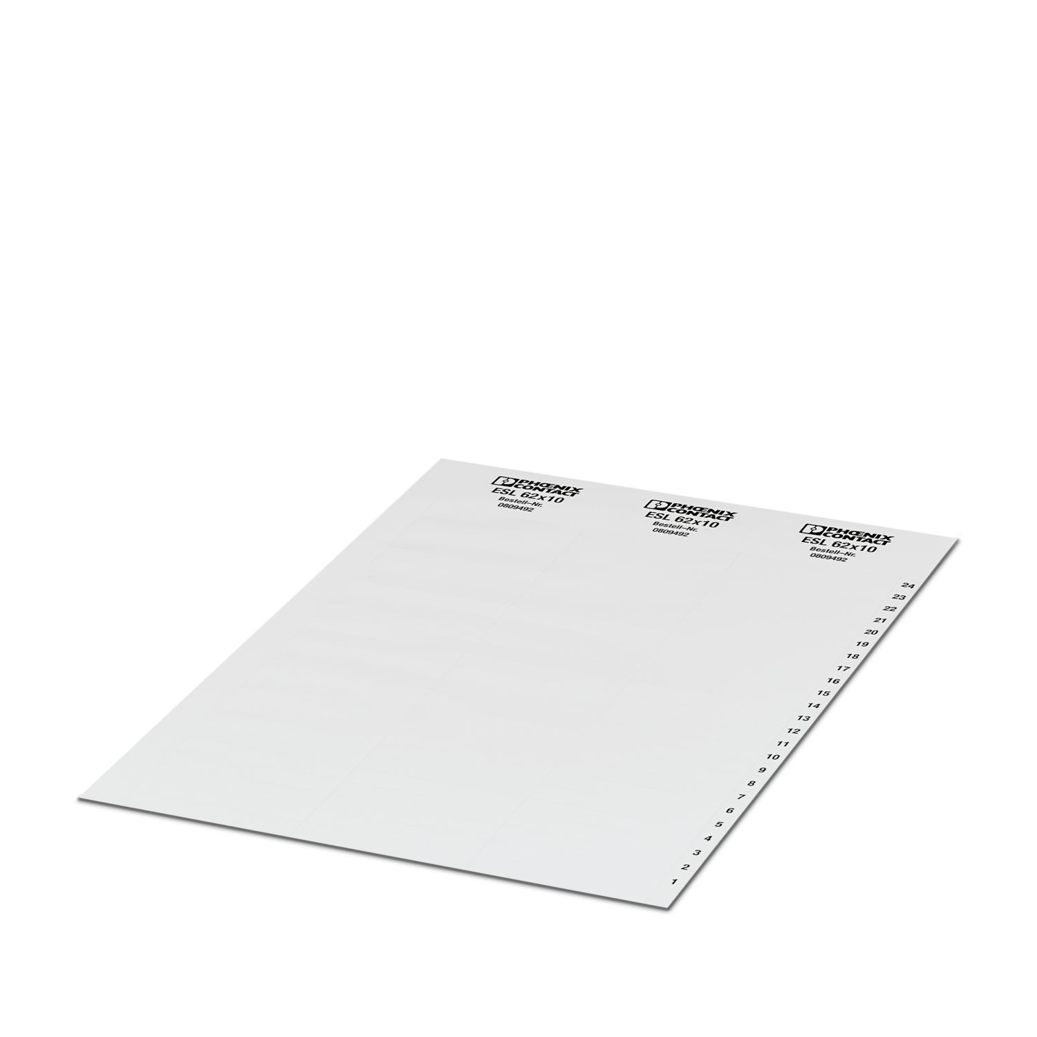
| Scope of supply | including Inline connectors and marking fields |
| No. of channels | 16 |
| Operating mode | Process data mode with one word |
| Special properties | Extreme conditions version |
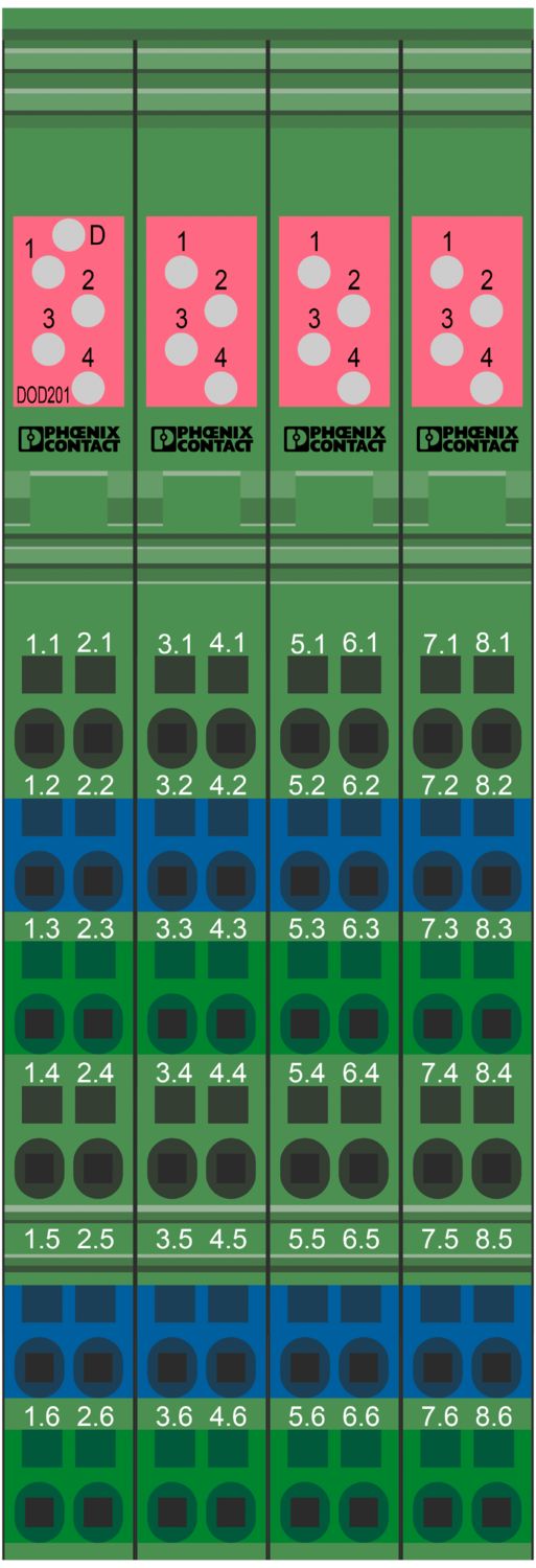
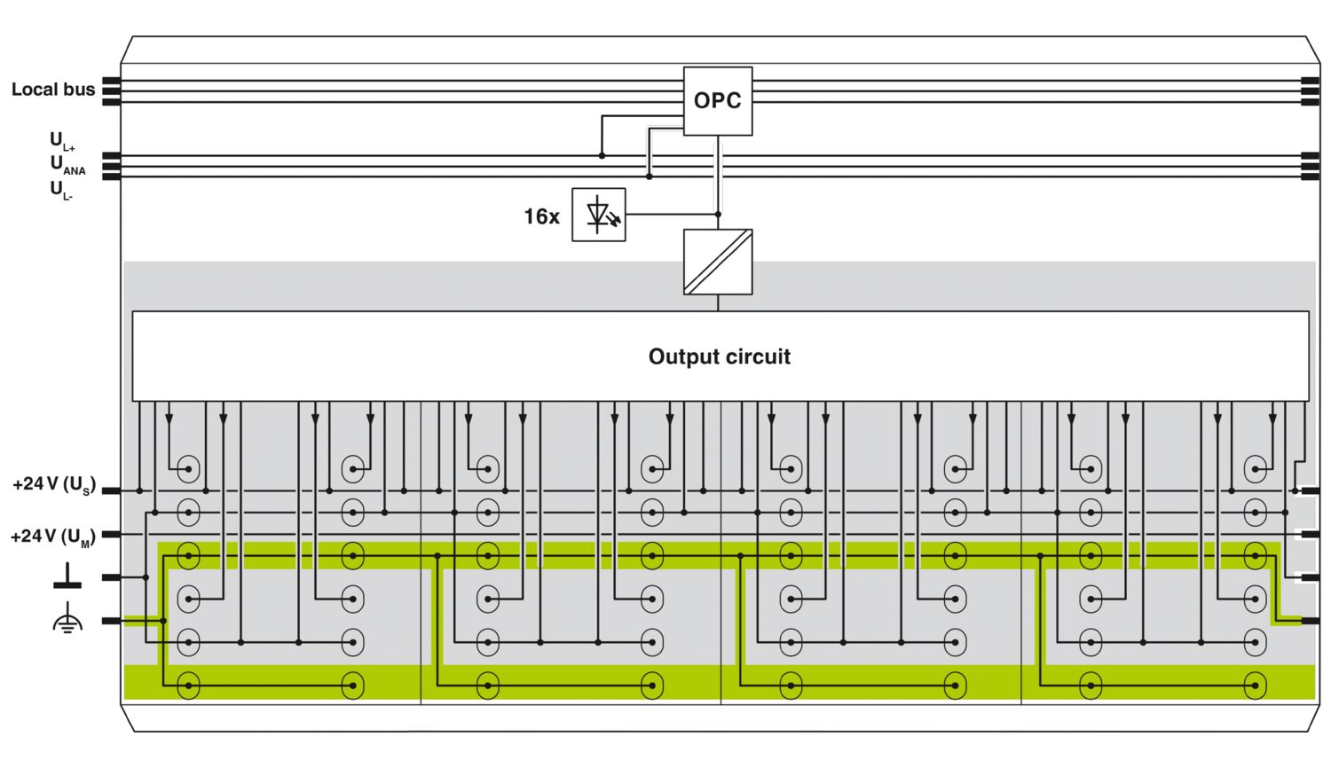
| Diagnostics messages | Short-circuit or overload of the digital outputs Error message in the diagnostic code (bus) and display (2 Hz) via the LED (D) on the module |
| Insulation characteristics | |
| Overvoltage category | II (IEC 60664-1, EN 60664-1) |
| Pollution degree | 2 (IEC 60664-1, EN 60664-1) |
| Potentials: Communications power (UL) | |
| Supply voltage | 7.5 V DC (via voltage jumper) |
| Current draw | max. 90 mA |
| Potentials: Segment circuit supply (US) | |
| Supply voltage | 24 V DC (via voltage jumper) |
| Supply voltage range | 19.2 V DC ... 30 V DC (including all tolerances, including ripple) |
| Current draw | max. 8 A |
| Electrical isolation/isolation of the voltage ranges | |
| Test voltage: 7.5 V supply (bus logics)/24 V supply (I/O) | 500 V AC, 50 Hz, 1 min |
| Test voltage: 24 V supply (I/O) / functional ground | 500 V AC, 50 Hz, 1 min |
| Test voltage: 7.5 V supply (bus logic)/functional ground | 500 V AC, 50 Hz, 1 min |
| Connection technology | |
| Connection name | Inline connector |
| Conductor connection | |
| Connection method | Spring-cage connection |
| Conductor cross section rigid | 0.08 mm² ... 1.5 mm² |
| Conductor cross section flexible | 0.08 mm² ... 1.5 mm² |
| Conductor cross section AWG | 28 ... 16 |
| Stripping length | 8 mm |
| Inline connector | |
| Connection method | Spring-cage connection |
| Conductor cross section, rigid | 0.08 mm² ... 1.5 mm² |
| Conductor cross section, flexible | 0.08 mm² ... 1.5 mm² |
| Conductor cross section AWG | 28 ... 16 |
| Stripping length | 8 mm |
| Ambient conditions | |
| Ambient temperature (operation) | -25 °C ... 55 °C (Standard) |
| -40 °C ... 70 °C (Extended, see section “Tested successfully: use under extreme ambient conditions” in the data sheet.) | |
| Degree of protection | IP20 |
| Air pressure (operation) | 70 kPa ... 106 kPa (up to 3000 m above sea level) |
| Air pressure (storage/transport) | 70 kPa ... 106 kPa (up to 3000 m above sea level) |
| Ambient temperature (storage/transport) | -40 °C ... 85 °C |
| Permissible humidity (operation) | 10 % ... 95 % (according to DIN EN 61131-2) |
| Permissible humidity (storage/transport) | 10 % ... 95 % (according to DIN EN 61131-2) |
| Protection class | III (IEC 61140, EN 61140, VDE 0140-1) |
| Mounting type | DIN rail mounting |