
SAC-8P-M12MS/1,1-PUR/M12MR SH
-
Sensor/actuator cable
1404560
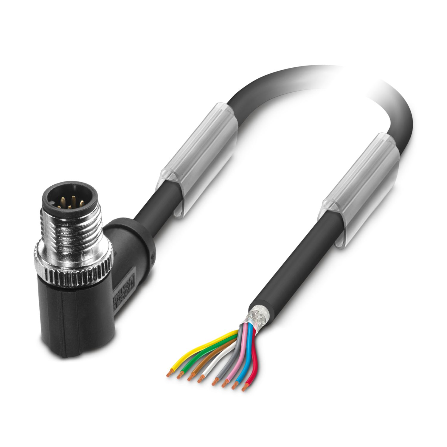
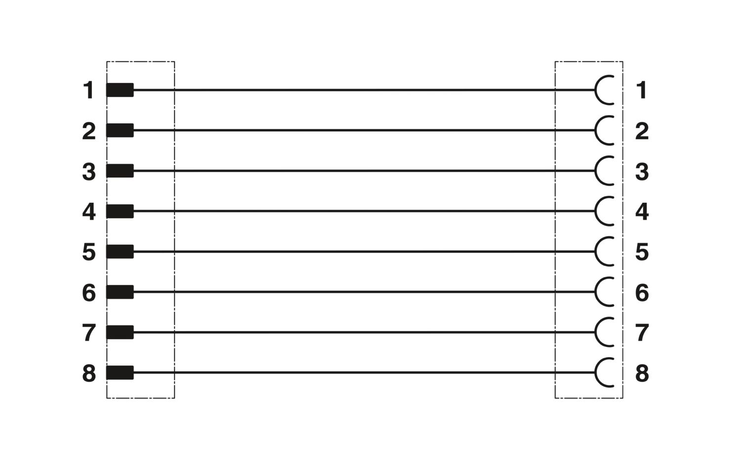
Sensor/actuator cable, 8-position, Plug straight M12, on Plug angled M12, cable length: 1.1 m
Product details
| Product type | Sensor/actuator cable |
| Number of positions | 8 |
| No. of cable outlets | 1 |
| Shielded | yes |
| Coding | A |
| Insulation characteristics | |
| Overvoltage category | II |
| Degree of pollution | 3 |
| Flammability rating according to UL 94 | HB |
| Insulation resistance | ≥ 100 MΩ |
| Nominal voltage UN | 30 V AC |
| 30 V DC | |
| Nominal current IN | 2 A |
| Status display | no |
| Status display present | no |
| Connection 1 | |
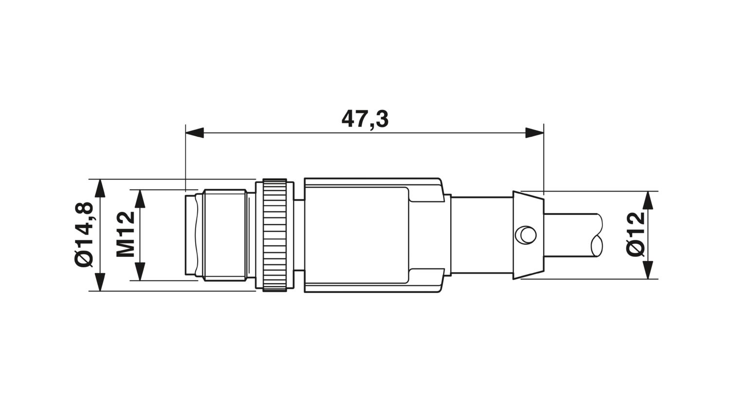
| Dimensional drawing |
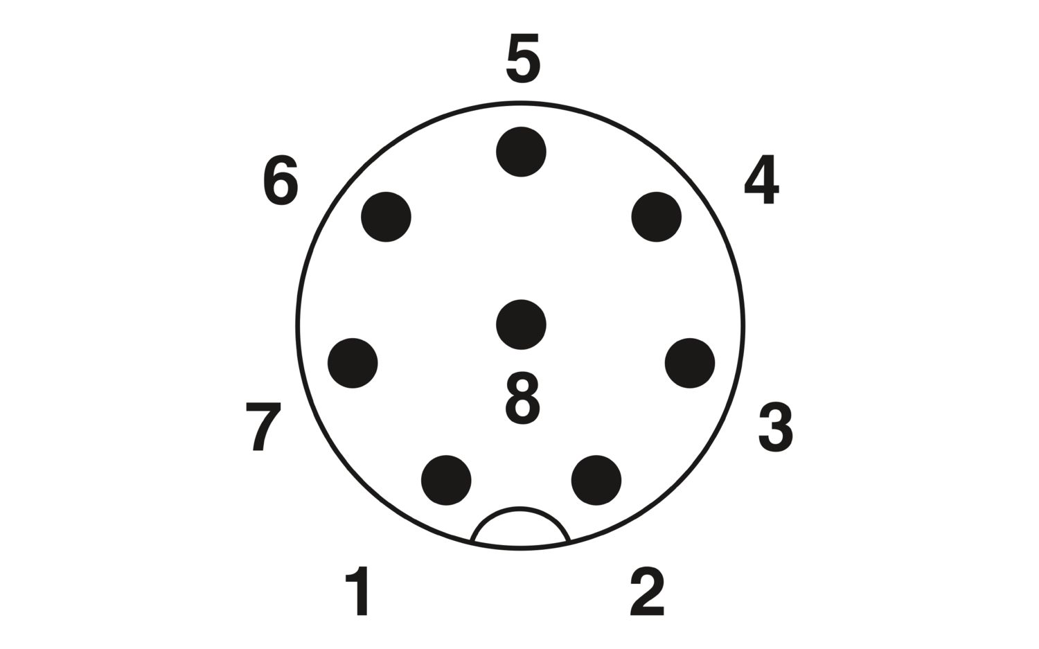
Pin assignment M12 plug, 8-pos., A-coded, view plug side
|
| Type | M12 Plug, angled, 8-position, shielded (Advanced Shielding Technology), Keying: A, Ethernet |
| Number of positions | 8 |
| Shielded | yes |
| Shielding | Advanced Shielding Technology |
| Signal type/category | Ethernet CAT5, 1 bps |
| Insertion/withdrawal cycles | ≥ 100 |
| Insulation resistance | ≥ 100 Ω |
| Overvoltage category | II |
| Degree of pollution | 3 |
| Tightening torque | 0.4 Nm (M12 connector) |
| Material Contact | CuZn |
| Material Contact surface | Ni/Au |
| Material Contact carrier | PA 6.6 |
| Material Screw connection | Die-cast zinc, nickel-plated |
| Material Grip body | TPU, hardly inflammable, self-extinguishing |
| Material Seal | FKM |
| Flammability rating according to UL 94 | V0 |
| Ambient temperature (operation) | -25 °C ... 85 °C |
| Standard designation | M12 connector |
| Standards/regulations | IEC 61076-2-101 |
| Connection 2 | |
| Type | Plug angled M12 |
| Number of positions | 8 |
| Cable length | 1.1 m |
| PUR halogen-free black [PUR] | |
| Dimensional drawing |
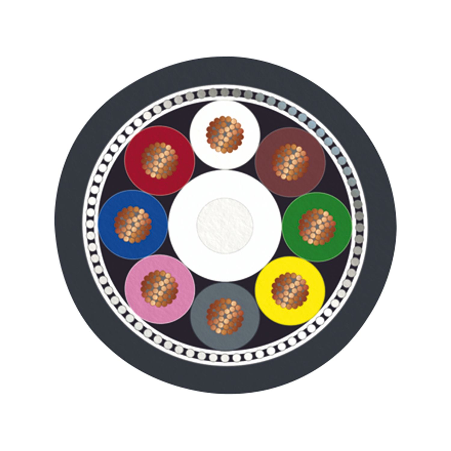
|
| Shielded | yes |
| UL AWM Style | 20549 / 10493 (80°C/300 V) |
| Cable weight | 53 kg/km |
| Cable type | PUR halogen-free black |
| Cable type (abbreviation) | PUR |
| External cable diameter | 5.90 mm ±0.2 mm |
| Outer sheath, material | PUR |
| External sheath, color | black-gray RAL 7021 |
| Thickness, outer sheath | approx. 0.50 mm |
| Conductor material | Bare Cu litz wires |
| Conductor structure signal line | 32x 0.10 mm |
| AWG signal line | 24 |
| Conductor cross-section | 8x 0.25 mm² (Signal line) |
| Material wire insulation | PP |
| Thickness, insulation | approx. 0.20 mm |
| Wire diameter incl. insulation | 1.17 mm ±0.02 mm |
| Single wire, color | brown, white, green, yellow, gray, pink, blue, red |
| Overall twist | 8 wires around filler to the core |
| Shielding | Tinned copper braided shield |
| Optical shield covering | 85 % |
| Nominal voltage, cable | ≤ 300 V AC |
| Test voltage Core/Shield | ≥ 2000.00 V AC (for 60 s) |
| Test voltage, cable | ≥ 3000 V AC (Spark test) |
| Cable resistance | ≤ 78 Ω/km (at 20 °C) |
| Cable insulation resistance | ≥ 1 GΩ*km (at 20 °C) |
| Minimum bending radius, fixed installation | 5 x D |
| Minimum bending radius, flexible installation | 10 x D |
| Number of bending cycles | 10000000 |
| Minimum bending radius, drag chain applications | 10 x D |
| Traversing path | 10 m |
| Traversing rate | 3 m/s |
| Acceleration | 10 m/s² |
| Torsion force | ± 180 °/m |
| Torsion cycles | ≥ 5000000 |
| Torsional frequency | 35 (cycles/min.) |
| Halogen-free | in accordance with DIN VDE 0472 part 815 |
| according to IEC 60754-1 | |
| Resistance to oil | in accordance with IEC 60811-404 |
| Flame resistance | in acc. with UL FT-2 |
| according to UL 758/1581 (horizontal) | |
| in accordance with UL 758/1581 FT2 | |
| According to DIN EN 60332-2-2 (20 s) | |
| Other resistance | hydrolysis and microbe resistant |
| Resistant to salt water | |
| low-abrasion | |
| partly UV-resistant (in accordance with DIN EN ISO 4892-2-A) | |
| Special properties | Flexible cable conduit capable |
| Ambient temperature (operation) | -25 °C ... 80 °C (Cable, flexible installation) |
| -40 °C ... 80 °C (cable, fixed installation) | |
| Ambient conditions | |
| Ambient temperature (operation) | -25 °C ... 90 °C (Plug / socket) |
| Specification | IEC 60512-6-4:2002-02 |
| IEC 60512-1-1:2002-02 | |
| IEC 60512-2-1:2002-02 | |
| IEC 60512-2-5:2003-05 | |
| Requirements, Contact resistance | Resistance difference ΔR ≤ 15 mΩ (for each channel) |
| Requirements, visual check | No defects that impair normal functionality. |
| Lowest frequency | 10 Hz |
| Highest frequency | 500 Hz |
| Amplitude | 0.35 mm |
| Acceleration | 5g |
| Sweep speed | 1 octave/min |
| No. of cycles | 10 |
| Test directions | X-, Y- and Z-axis |
| Shock | |
| Specification | IEC 60512-6-3:2002-02 |
| IEC 60512-1-1:2002-02 | |
| IEC 60512-2-1:2002-02 | |
| IEC 60512-2-5:2003-05 | |
| Requirements, Contact resistance | Resistance difference ΔR ≤ 15 mΩ (for each channel) |
| Requirements, visual check | No defects that impair normal functionality. |
| Acceleration | 50g |
| Test directions | X-, Y- and Z-axis |
| Pulse shape | Half-sine |
| Number of shocks per direction | 3 |
| Duration of the nominal shock | 11 ms |
| Specification | IEC 60512-11-4:2002-02 |
| IEC 60512-1-1:2002-02 | |
| IEC 60512-2-1:2002-02 | |
| IEC 60512-3-1:2002-02 | |
| IEC 60512-4-1:2003-05 | |
| Requirements, Contact resistance | Resistance difference ΔR ≤ 15 mΩ (for each channel) |
| Requirements, insulation resistance | RI ≥ 100 MΩ |
| Requirements, dielectric strength | There must be no electrical flashovers or disruptive charges for the duration of the test. The maximum permissible leakage current must not be exceeded. |
| Requirements, visual check | No defects that impair normal functionality. |
| No. of cycles | 5 |
| Dwell time | 30 min |
| Transition duration | ≤ 10 s |
| Minimum temperature | -25 °C |
| Maximum temperature | +85 °C |
| Specification | IEC 60512-11-9:2002-02 |
| IEC 60512-1-1:2002-02 | |
| IEC 60512-3-1:2002-02 | |
| Requirements, insulation resistance | RI ≥ 100 MΩ |
| Requirements, visual check | No defects that impair normal functionality. |
| Test duration | 16 h |
| Temperature for testing | 85 °C |
| Specification | IEC 60512-11-12:2002-02 |
| IEC 60512-1-1:2002-02 | |
| Requirements, visual check | No defects that impair normal functionality. |
| Test duration | 24 h |
| Temperature for testing | 40 °C |
| Specification | IEC 60512-11-10:2002-02 |
| IEC 60512-1-1:2002-02 | |
| Requirements, visual check | No defects that impair normal functionality. |
| Test duration | 2 h |
| Temperature for testing | -25 °C |
| Specification | IEC 60512-11-12:2002-02 |
| IEC 60512-1-1:2002-02 | |
| IEC 60512-2-1:2002-02 | |
| IEC 60512-3-1:2002-02 | |
| IEC 60512-4-1:2003-05 | |
| IEC 60512-13-2:2006-02 | |
| Requirements, Contact resistance | Resistance difference ΔR ≤ 15 mΩ (for each channel) |
| Requirements, insulation resistance | RI ≥ 100 MΩ |
| Requirements, dielectric strength | There must be no electrical flashovers or disruptive charges for the duration of the test. The maximum permissible leakage current must not be exceeded. |
| Requirements, insertion and withdrawal forces | Maximum allowable insertion force Finsertion < 23 N Maximum allowable withdrawal force Fwithdrawal < 30 N |
| Requirements, visual check | No defects that impair normal functionality. |
| Test duration | 24 h |
| Temperature for testing | 40 °C |
| Specification | IEC 60512-1-1:2002-02 |
| IEC 60512-3-1:2002-02 | |
| IEC 60512-4-1:2003-05 | |
| Requirements | Water that is sprayed against the housing as a jet from any direction must not have any harmful effect. |
| Requirements, insulation resistance | RI ≥ 100 MΩ |
| Requirements, dielectric strength | There must be no electrical flashovers or disruptive charges for the duration of the test. The maximum permissible leakage current must not be exceeded. |
| Requirements, visual check | No defects that impair normal functionality. |
| Test duration | 1 min/m² at least 3 min |
| Specification | IEC 60512-1-1:2002-02 |
| IEC 60512-3-1:2002-02 | |
| IEC 60512-4-1:2003-05 | |
| Requirements | Water must not penetrate in a harmful quantity when the housing is temporarily submerged in water under standard pressure and time conditions. |
| Requirements, insulation resistance | RI ≥ 100 MΩ |
| Requirements, dielectric strength | There must be no electrical flashovers or disruptive charges for the duration of the test. The maximum permissible leakage current must not be exceeded. |
| Requirements, visual check | No defects that impair normal functionality. |
| Test duration | 30 min |
| Specification | IEC 60512-1-1:2002-02 |
| IEC 60512-2-1:2002-02 | |
| IEC 60512-3-1:2002-02 | |
| IEC 60512-13-2:2006-02 | |
| Requirements | Dust must not enter the housing. |
| Requirements, Contact resistance | Resistance difference ΔR ≤ 15 mΩ (for each channel) |
| Requirements, insertion and withdrawal forces | Maximum allowable insertion force Finsertion < 23 N Maximum allowable withdrawal force Fwithdrawal < 30 N |
| Requirements, visual check | No defects that impair normal functionality. |
| Test duration | 8 h |
| Specification | IEC 60512-13-5:2006-02 |
| Requirements | No damage that can impair normal functionality. Connectors must only be able to be plugged in when they are in the correct position and combination. The design must prevent mismatching. Polarization prevents incorrect electrical contact. |
| Insertion force | 1,5 x mating force; at least 35 N |
| Specification | IEC 60512-9-1:2010-03 |
| IEC 60512-1-1:2002-02 | |
| IEC 60512-2-1:2002-02 | |
| Requirements, Contact resistance | Resistance difference ΔR ≤ 15 mΩ (for each channel) |
| Requirements, visual check | No defects that impair normal functionality. |
| No. of cycles | 50 |
| Specification | IEC 60512-11-7:2003-05 |
| Requirements | No damage (corrosion) to the metal body that impairs normal functionality. |
| Requirements, Contact resistance | Resistance difference ΔR ≤ 15 mΩ (for each channel) |
| Test duration | 4 days |
| Test procedure | Method 4 |
| Specification | IEC 60512-9-1:2010-03 |
| Requirements, Contact resistance | Resistance difference ΔR ≤ 15 mΩ (for each channel) |
| Requirements, insulation resistance | RI ≥ 100 MΩ |
| Requirements, dielectric strength | There must be no electrical flashovers or disruptive charges for the duration of the test. The maximum permissible leakage current must not be exceeded. |
| Requirements, visual check | No defects that impair normal functionality. |
| No. of cycles | 50 |
| Specification | IEC 60512-11-4:2002-02 |
| IEC 60512-1-1:2002-02 | |
| IEC 60512-2-1:2002-02 | |
| IEC 60512-3-1:2002-02 | |
| IEC 60512-4-1:2003-05 | |
| Requirements, Contact resistance | Resistance difference ΔR ≤ 15 mΩ (for each channel) |
| Requirements, insulation resistance | RI ≥ 100 MΩ |
| Requirements, dielectric strength | There must be no electrical flashovers or disruptive charges for the duration of the test. The maximum permissible leakage current must not be exceeded. |
| Requirements, visual check | No defects that impair normal functionality. |
| No. of cycles | 5 |
| Dwell time | 30 min |
| Transition duration | ≤ 10 s |
| Minimum temperature | -25 °C |
| Maximum temperature | +85 °C |
| Specification | IEC 60512-9-1:2010-03 |
| IEC 60512-1-1:2002-02 | |
| IEC 60512-2-1:2002-02 | |
| Requirements, Contact resistance | Resistance difference ΔR ≤ 15 mΩ (for each channel) |
| Requirements, visual check | No defects that impair normal functionality. |
| No. of cycles | 100 |
| Requirements | No change in the material properties that would limit the intended use. |
| Test duration | 24 h |
| Temperature for testing | +85 °C ±2 °C |
| Test liquid | IRM 902 |
| Specification | IEC 61373:2010-05 |
| IEC 60512-1-1:2002-02 | |
| IEC 60512-2-1:2002-02 | |
| Requirements, Contact resistance | Resistance difference ΔR ≤ 15 mΩ (for each channel) |
| Requirements, visual check | No defects that impair normal functionality. |
| Acceleration | 5g |
| Test directions | X-, Y- and Z-axis |
| Category | 1 |
| Pulse shape | Half-sine |
| Number of shocks per direction | 3 |
| Shock duration | 30 ms |
| Specification | IEC 61373:2010-05 |
| IEC 60512-1-1:2002-02 | |
| IEC 60512-2-1:2002-02 | |
| Requirements, Contact resistance | Resistance difference ΔR ≤ 15 mΩ (for each channel) |
| Requirements, visual check | No defects that impair normal functionality. |
| Acceleration | 30g |
| Test directions | X-, Y- and Z-axis |
| Category | 2 |
| Pulse shape | Half-sine |
| Number of shocks per direction | 3 |
| Shock duration | 18 ms |
| Specification | IEC 61373:2010-05 |
| IEC 60512-1-1:2002-02 | |
| IEC 60512-2-1:2002-02 | |
| Requirements, Contact resistance | Resistance difference ΔR ≤ 15 mΩ (for each channel) |
| Requirements, visual check | No defects that impair normal functionality. |
| Lowest frequency | 2 Hz |
| Highest frequency | 250 Hz |
| Test directions | X-, Y- and Z-axis |
| Category | 2 |
| Specification | IEC 60512-2-1:2002-02 |
| Requirements | Resistance difference ΔR ≤ 15 mΩ (for each channel) Rmax - Rwire ≤ 10 mΩ (for each channel) Rshield - Rcableshield ≤ 100 mΩ |
| Specification | IEC 60512-3-1:2002-02 |
| Requirements, insulation resistance | RI ≥ 100 MΩ |
| Specification | IEC 60512-4-1:2003-05 |
| Requirements, dielectric strength | There must be no electrical flashovers or disruptive charges for the duration of the test. The maximum permissible leakage current must not be exceeded. |
| Test voltage | 0.65 kV AC |
| Test duration | 60 s |
| Specification | IEC 60512-9-2:2011-11 |
| IEC 60512-1-1:2002-02 | |
| IEC 60512-2-1:2002-02 | |
| IEC 60512-3-1:2002-02 | |
| IEC 60512-4-1:2003-05 | |
| Requirements | The sum of the ambient temperature and temperature rise of a connector must not exceed the upper limiting temperature. |
| Requirements, Contact resistance | Resistance difference ΔR ≤ 15 mΩ (for each channel) |
| Requirements, insulation resistance | RI ≥ 100 MΩ |
| Requirements, dielectric strength | There must be no electrical flashovers or disruptive charges for the duration of the test. The maximum permissible leakage current must not be exceeded. |
| Requirements, visual check | No defects that impair normal functionality. |
| Test current | 2 A |
| Test duration | 1000 h |
| Temperature for testing | 40 °C |
| Upper limiting temperature | 85 °C |
| Specification | IEC 60352-2:2006-02 |
| Connection method | Crimp connections |
| Specification | IEC 60512-1-1:2002-02 |
| Requirements, visual check | No defects that impair normal functionality. |
| Dimensional examination | |
| Specification | IEC 60512-1-2:2002-02 |
| Requirements | All individual parts have been approved for the current revision status. |
| Specification | IEC 60512-13-2:2006-02 |
| Requirements, insertion and withdrawal forces | Maximum allowable insertion force Finsertion < 23 N Maximum allowable withdrawal force Fwithdrawal < 30 N |
| Specification | IEC 60512-7-1:2010-03 |
| IEC 60512-1-1:2002-02 | |
| Requirements, visual check | Loose parts or damage that would impair functionality are not permitted. |