
The module is designed for use within an Axioline F station. It is used to acquire and output digital signals. The filter times of the inputs can be adjusted to increase noise immunity. Filter times of 100 μs enable the user to implement a counter function with a maximum input frequency of 5 kHz in the application. The outputs are protected against short circuit and overload.
AXL F DI16/1 DO8/2-2A 2H
-
Digital module
2702291
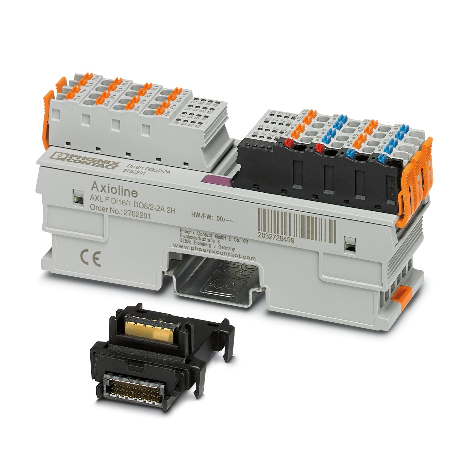
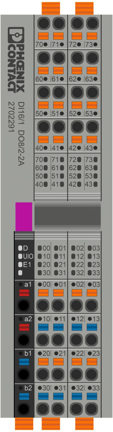
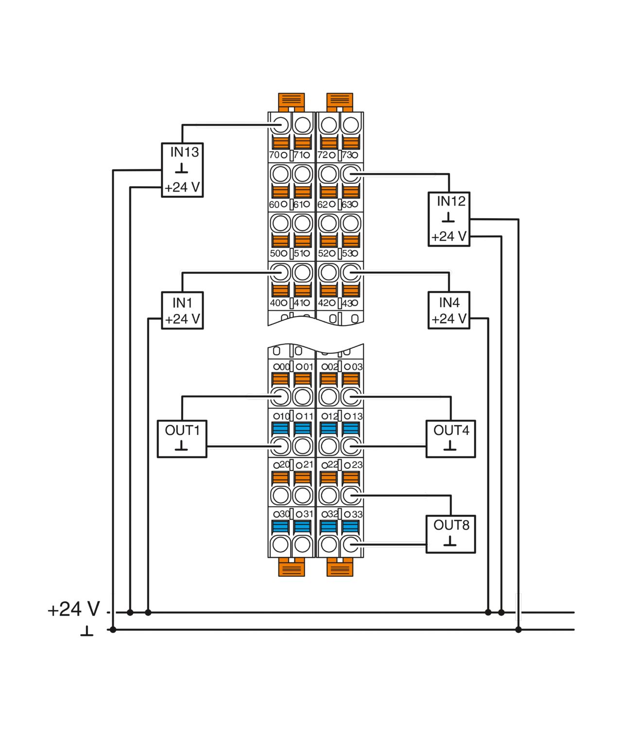
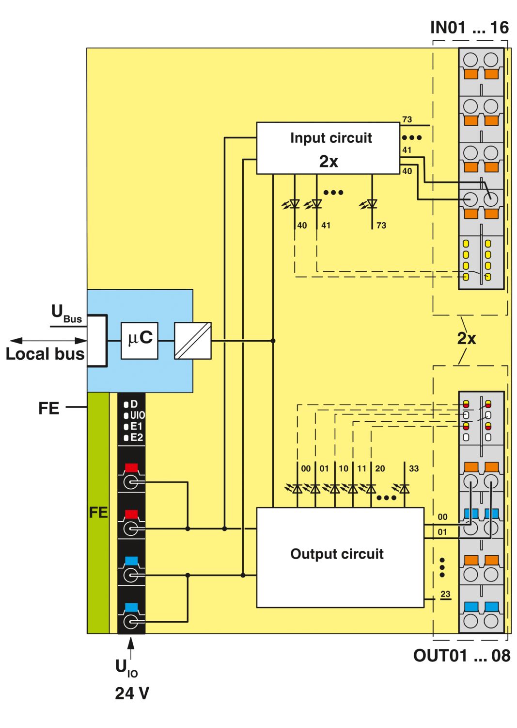

Axioline F, Digital I/O module, Digital inputs: 16, 24 V DC, connection technology: 1-conductor, Digital outputs: 8, 24 V DC, 2 A, connection technology: 2-conductor, transmission speed in the local bus: 100 Mbps, degree of protection: IP20, including bus base module and Axioline F connectors; The product is being prepared for compliance with the Cyber Resilience Act (CRA).
Free download available.
Downloads
Product details
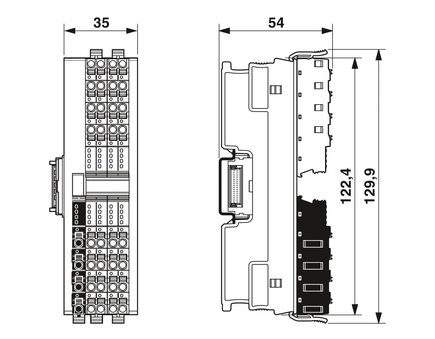
| Dimensional drawing |
|
| Width | 35 mm |
| Height | 129.9 mm |
| Depth | 54 mm |
| Note on dimensions | The depth applies when a TH 35-7.5 DIN rail is used (in accordance with EN 60715). |
| Note on application | Only for industrial use |
| Note on application | As things stand now, we are preparing the product so that, as of December 11, 2027, it will comply with the requirements of the EU Cyber Resilience Act (CRA) based on the information currently available regarding the CRA. |
| Mounting type | DIN rail mounting |
| Mounting position | any (no temperature derating) |
| Color (Housing) | gray (RAL 7042) |
| Axioline F local bus | |
| Number of interfaces | 2 |
| Connection method | Bus base module |
| Transmission speed | 100 Mbps |
| Programming data | |
| Input address area | 2 Byte |
| Output address area | 2 Byte |
| Fieldbus data telegram (PROFIBUS) | |
| Required parameter data | 3 Byte |
| Required configuration data | 7 Byte |
| Digital: | |
| Input name | Digital inputs |
| Description of the input | EN 61131-2 types 1 and 3 |
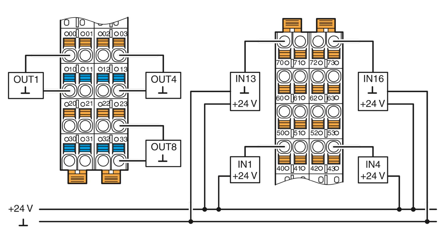
| Number of inputs | 16 |
| Connection method | Push-in connection |
| Connection technology | 1-conductor |
| Input voltage range "0" signal | -3 V DC ... 5 V DC |
| Input voltage range "1" signal | 11 V DC ... 30 V DC |
| Nominal input voltage UIN | 24 V DC |
| Nominal input current at UIN | 2.4 mA |
| Current flow | linear until nominal current is reached, then constantly approx. 2.4 mA |
| Input filter time | 3000 µs (Default) |
| 1000 µs | |
| < 100 µs | |
| Process data update | < 150 µs |
| Protective circuit | Polarity reversal protection of the inputs; parallel diode (30 V, 5 s) |
| Digital: | |
| Output name | Digital outputs |
| Design of digital output | Semiconductor |
| Connection method | Push-in connection |
| Connection technology | 2-conductor |
| Number of outputs | 8 |
| Protective circuit | Short-circuit protection, overload protection of the outputs; electronic |
| Output voltage | 24 V DC |
| Limitation of the voltage induced on circuit interruption | -25.8 V ... -15 V |
| Max. current carrying capacity per output | max. 2 A |
| Maximum output current per module | max. 16 A (Provide external protection; if the total current of 8 A is exceeded, connect the supply at the power connector parallel via both terminal points.) |
| Nominal output voltage | 24 V DC |
| Load min. | 10 kΩ |
| Output voltage when switched off | max. 1 V |
| Output current when switched off | max. 300 µA |
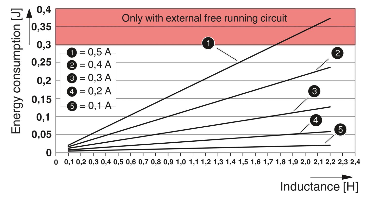
| Nominal load, inductive | max. 48 VA (1.2 H, 12 Ω, at nominal load) |
| Nominal load, lamp | max. 48 W (at nominal voltage) |
| Nominal load, ohmic | max. 48 W (12 Ω, at nominal load) |
| Behavior with overload | Shutdown with automatic restart |
| Behavior with inductive overload | Output can be destroyed |
| Switching frequency | max. 3000 per second (with at least 50 mA load current) |
| max. 1 per second (with inductive load) | |
| max. 4 per second (with nominal lamp load) | |
| Reverse voltage resistance to short pulses | limited protection up to 0.5 A for 1 s |
| Signal delay | max. 150 µs (when switched on) |
| max. 150 µs (when switched off, with at least 50 mA load current) | |
| Overcurrent shut-down | as of 2.1 A |
| Output current with ground connection interrupt when switched off | < 1 mA |
| Product type | I/O component |
| Product family | Axioline F |
| Type | block modular |
| Mounting position | any (no temperature derating) |
| Scope of supply | including bus base module and Axioline F connectors |
| Special properties | The product is being prepared for compliance with the Cyber Resilience Act (CRA) |
| Insulation characteristics | |
| Overvoltage category | II (IEC 60664-1, EN 60664-1) |
| Pollution degree | 2 (IEC 60664-1, EN 60664-1) |
| Maximum power dissipation for nominal condition | 7.95 W |
| Potentials: Axioline F local bus supply (UBus) | |
| Supply voltage | 5 V DC (via bus base module) |
| Current draw | max. 120 mA (up to HW 01) |
| max. 60 mA (from HW 02) | |
| Potentials: Supply for digital input and output modules (UIO) | |
| Supply voltage | 24 V DC |
| Supply voltage range | 19.2 V DC ... 30 V DC (including all tolerances, including ripple) |
| Current draw | max. 16 A (Provide external protection; if the total current of 8 A is exceeded, connect the supply at the power connector parallel via both terminal points.) |
| Current consumption | typ. 10 mA (without connected peripherals) |
| Protective circuit | Surge protection; electronic (35 V, 0.5 s) |
| Reverse polarity protection; parallel diode; with external 5 A fuse (only for commissioning) | |
| Protection | max. 16 A (polarity reversal protection up to 5 A) |
| Electrical isolation/isolation of the voltage ranges | |
| Test voltage: 5 V supply of the local bus (UBus) / 24 V supply (I/Os) | 500 V AC, 50 Hz, 1 min |
| Test voltage: 5 V supply of the local bus (UBus) / functional ground | 500 V AC, 50 Hz, 1 min |
| Test voltage: 24 V supply (I/O) / functional ground | 500 V AC, 50 Hz, 1 min |
| Connection technology | |
| Connection name | Axioline F connectors (digital inputs) |
| Note on the connection method | Please observe the information provided on conductor cross-sections in the “Axioline F: system and installation” user manual. |
| Axioline F connectors (digital inputs) | |
| Connection method | Push-in connection |
| Note on the connection method | Please observe the information provided on conductor cross-sections in the “Axioline F: system and installation” user manual. |
| Conductor cross-section, rigid | 0.2 mm² ... 1.5 mm² |
| Conductor cross-section, flexible | 0.2 mm² ... 1.5 mm² |
| Conductor cross-section AWG | 24 ... 16 |
| Stripping length | 8 mm |
| Axioline F connectors (supply and digital outputs) | |
| Connection method | Push-in connection |
| Note on the connection method | Please observe the information provided on conductor cross-sections in the “Axioline F: system and installation” user manual. |
| Conductor cross-section, rigid | 0.5 mm² ... 1.5 mm² |
| Conductor cross-section, flexible | 0.5 mm² ... 1.5 mm² |
| Conductor cross-section AWG | 20 ... 16 |
| Stripping length | 8 mm |
| Ambient conditions | |
| Ambient temperature (operation) | -25 °C ... 60 °C |
| Degree of protection | IP20 |
| Air pressure (operation) | 70 kPa ... 106 kPa (up to 3000 m above sea level) |
| Air pressure (storage/transport) | 70 kPa ... 106 kPa (up to 3000 m above sea level) |
| Ambient temperature (storage/transport) | -40 °C ... 85 °C |
| Permissible humidity (operation) | 5 % ... 95 % (non-condensing) |
| Permissible humidity (storage/transport) | 5 % ... 95 % (non-condensing) |
| Mechanical test | |
| Vibration resistance in accordance with EN 60068-2-6/IEC 60068-2-6 | 5g |
| Shock in accordance with EN 60068-2-27/IEC 60068-2-27 | 30g |
| Continuous shock in accordance with EN 60068-2-27/IEC 60068-2-27 | 10g |
| Protection class | III (IEC 61140, EN 61140, VDE 0140-1) |
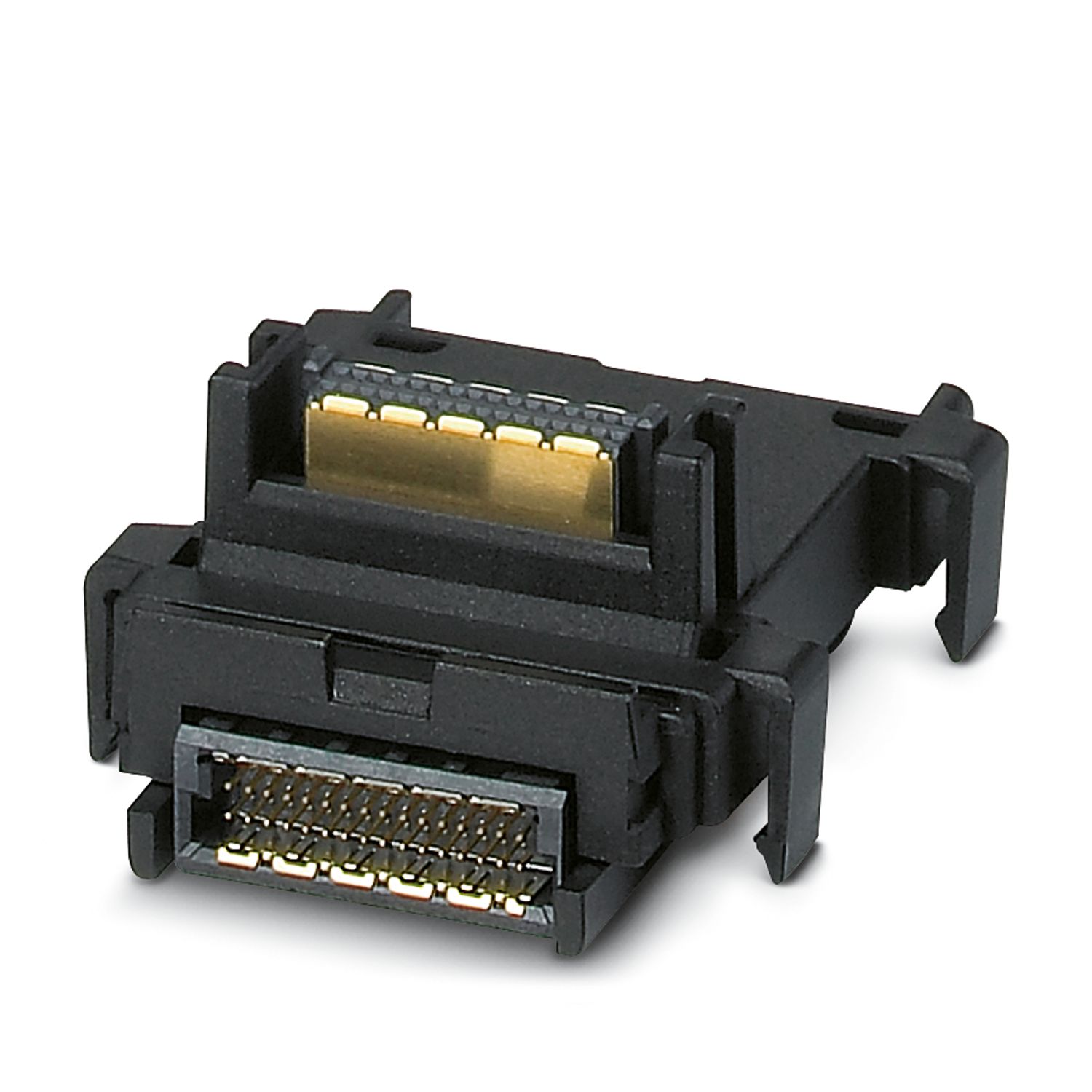

Your advantages
16 digital inputs in accordance with EN 61131-2 type 1 and type 3
24 V DC, 2.4 mA
Connection of sensors in 1-conductor technology
Filter times can be adjusted in three increments: < 100 µs, 1000 µs or 3000 µs
Maximum input frequency: 5 kHz
8 digital outputs
24 V DC, 2 A
Connection of actuators in 2-conductor technology
Minimum update time of < 100 μs
Device rating plate stored