UL Recognized
Approval ID: E468743| Nominal voltage UN | Nominal current IN | Cross section AWG | Cross section mm2 | |
|---|---|---|---|---|
| keine | ||||
| Power | 37 A | - 10 | ||
| Signal | 10 A | - 14 | ||



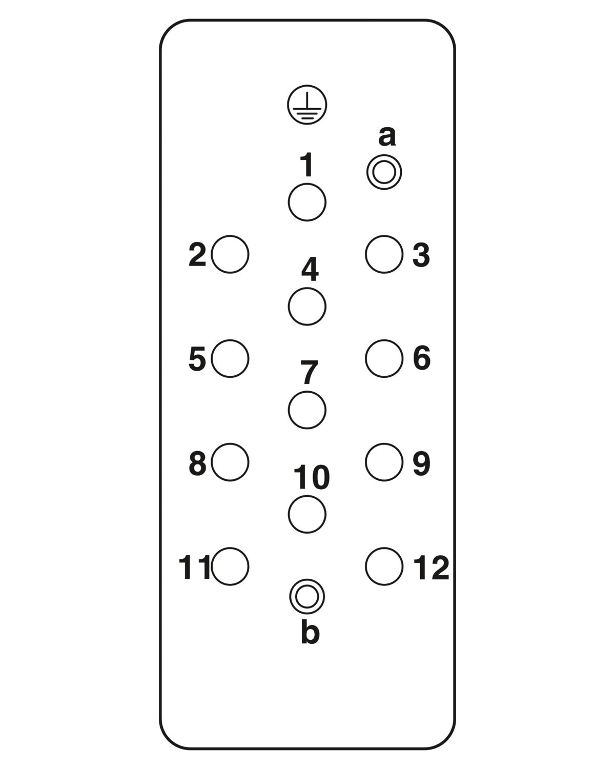

Contact insert, number of positions: 12+2+PE, size: B16, power contacts: 12, control contacts: 2, Socket, Crimp connection, 690 V, 40 A, 1.5 mm2 ... 10 mm2, application: Power/signal
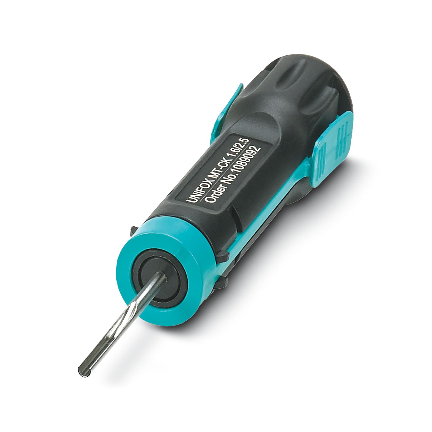
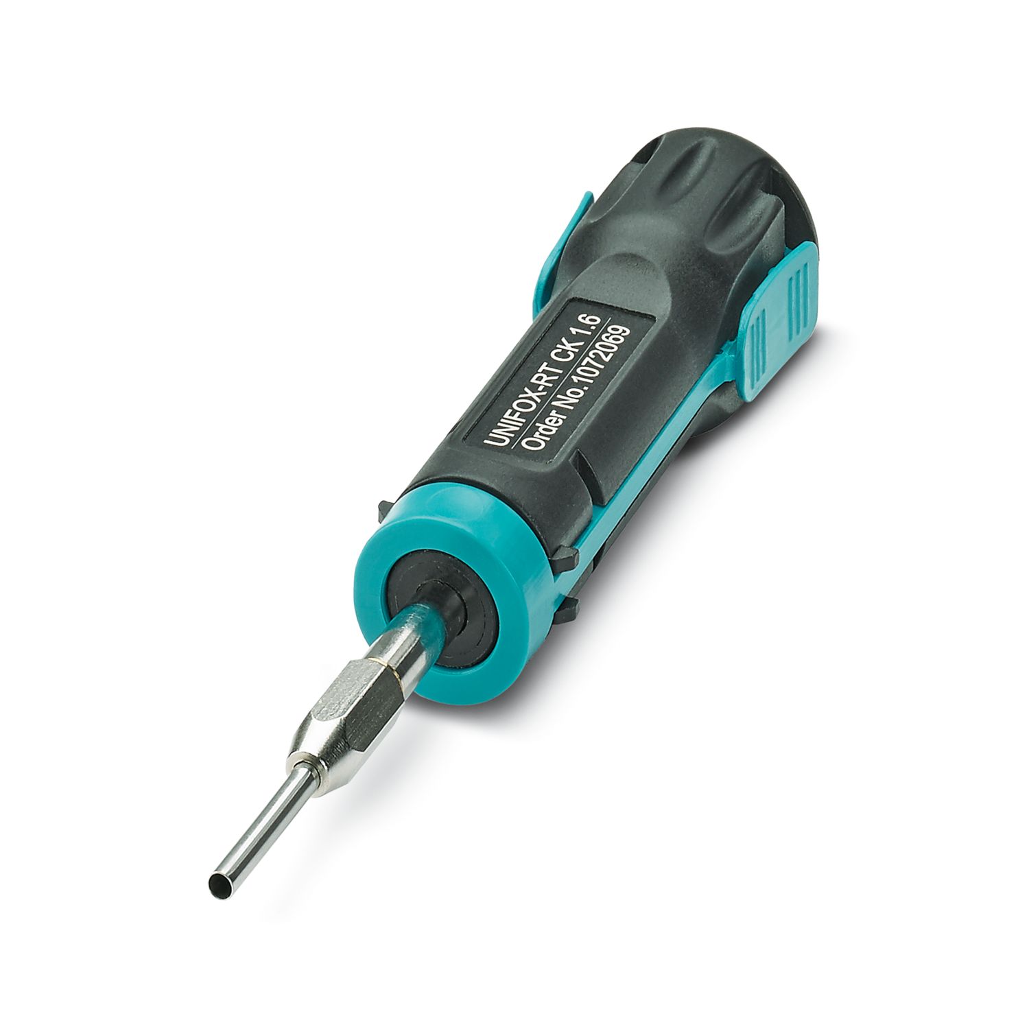
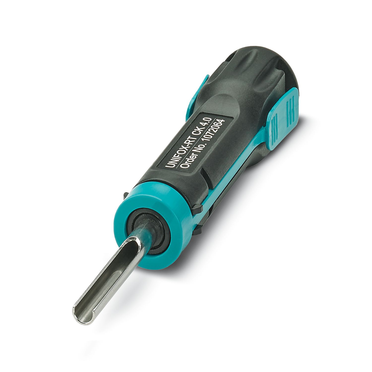
| General | For HEAVYCON ADVANCE and HEAVYCON housing of type B16/B32, power contacts: CK 4,0-ED, control contacts: CK 1,6-ED (crimp contacts not supplied as standard) |
| General | Connectors may be operated only when there is no load/voltage. |
| Assembly note | To ensure correct use, installation in housing with IP54 protection or better is required |
| Product type | Contact insert with a fixed no. of positions |
| Series | HC-K |
| Application | Power/signal |
| Type | B16 |
| B32 | |
| Number of positions | 14 |
| Connection profile | 12+2+PE |
| Contact numbering | 1 - 12 (power contacts) |
| 1 - 2 (control contacts) | |
| No. of power contacts | 12 |
| No. of control contacts | 2 |
| Contact material type | turned |
| Insulation characteristics | |
| Overvoltage category | III |
| Degree of pollution | 3 |
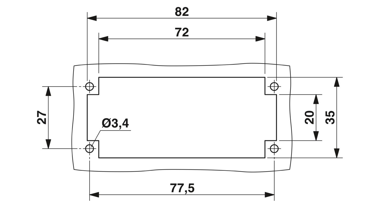
| Dimensional drawing |
|
| Width | 34 mm |
| Height | 41.5 mm |
| Length | 84.5 mm |
| Drill hole distance, horizontal | 77.5 mm |
| Mechanical characteristics | |
| Contact diameter | 4 mm |
| Connection technology | |
| Connection technology | Crimp connection (power contacts) |
| Crimp connection (control contacts) | |
| Conductor connection | |
| Conductor cross-section | 1.5 mm² ... 10 mm² (power contacts) |
| 0.14 mm² ... 2.5 mm² (control contacts) | |
| Connection cross section AWG | 16 ... 8 (power contacts) |
| 26 ... 14 (control contacts) | |
| Tightening torque | 0.8 Nm ... 1.2 Nm (PE connection) |
| 0.5 Nm ... 0.8 Nm (Mounting screws for mounting in the HEAVYCON housing) | |
| Stripping length of the individual wire | 9 mm (Power 1.5 mm² ... 2.5 mm²) |
| 8 mm (Control contacts, with a cross section of 0.14 mm² ... 1.5 mm²) | |
| 9.5 mm (Power contacts, for cross-sections of 4 mm² ... 10 mm²) | |
| 6 mm (Control contacts, with a cross section of 2.5 mm²) | |
| Rated voltage (III/3) | 690 V (power contacts) |
| 250 V (control contacts) | |
| Rated surge voltage | 8 kV (power contacts) |
| 4 kV (control contacts) | |
| Rated current | 40 A (power contacts) |
| 10 A (control contacts) |
| Mechanical data | |
| Insertion/withdrawal cycles | ≥ 500 |
| Flammability rating according to UL 94 | V0 |
| Contact material | Cu alloy |
| Contact carrier material | PC |
| Material of contact surface, power contact | Ag |
| Material of contact surface, control contact | Ag (alternatively Au) |
| Ambient conditions | |
| Ambient temperature (operation) | -40 °C ... 125 °C (including heating up of contacts) |
| Service life test group | |
| Specification | IEC 61984:2008-10 |
| IEC 60512-1-1:2002-02 | |
| IEC 60512-2-1:2002-02 | |
| IEC 60512-2-2:2003-05 | |
| IEC 60512-4-1:2003-05 | |
| IEC 60512-9-1:2010-03 | |
| Requirements, Contact resistance | The contact resistance must not increase by more than 50% of the reference value or ≤ 5 mΩ. The higher value applies. |
| Requirements, dielectric strength | There must be no electrical flashovers or disruptive charges for the duration of the test. The maximum permissible leakage current must not be exceeded. |
| Requirements, visual check | No defects that impair normal functionality. |
| No. of cycles | 500 |
| Temperature rise | |
| Specification | IEC 60512-5-1:2002-02 |
| Requirements | The specified upper limiting temperature must not be exceeded. |
| Upper limiting temperature | 125 °C |
| Climatic test group | |
| Specification | IEC 61984:2008-10 |
| IEC 60512-11-10:2002-02 | |
| IEC 60512-11-9:2002-02 | |
| IEC 60512-11-7:2003-05 | |
| IEC 60512-4-1:2003-05 | |
| Requirements, Contact resistance | The contact resistance must not increase by more than 50% of the reference value or ≤ 5 mΩ. The higher value applies. |
| Requirements, dielectric strength | There must be no electrical flashovers or disruptive charges for the duration of the test. The maximum permissible leakage current must not be exceeded. |
| Requirements, visual check | No defects that impair normal functionality. |
| Test current | 1 A |
| Cold stress | -40 °C/2 h |
| Thermal stress | 125 °C/168 h |
| Corrosive stress | 0.2 dm3 SO2 / 40 °C 3 °C / 24 h / 1 cycle |
| Specification | IEC 60068-2-6:2007-12 |
| Contact disturbance requirement | Duration of the disturbance: max. 1 μs |
| Requirements, Contact resistance | The contact resistance must not increase by more than 50% of the reference value or ≤ 5 mΩ. The higher value applies. |
| Requirements, visual check | No damage that can affect the intended use. |
| Test duration | 2.5 h per axis |
| Lowest frequency | 10 Hz |
| Highest frequency | 150 Hz |
| Amplitude | 0.35 mm |
| Acceleration | 5g |
| Sweep speed | 1 octave/min |
| Test directions | X-, Y- and Z-axis |
| Vibration, broadband noise | |
| Specification | IEC 61373:2010-05 |
| Contact disturbance requirement | Duration of the disturbance: max. 1 μs |
| Requirements, Contact resistance | The contact resistance must not increase by more than 50% of the reference value or ≤ 5 mΩ. The higher value applies. |
| Requirements, visual check | No damage that can affect the intended use. |
| Test duration | 5 h per axis |
| Lowest frequency | 5 Hz |
| Highest frequency | 150 Hz |
| Acceleration | 0.6 g |
| Test directions | X-, Y- and Z-axis |
| Category | 1 |
| Class | B |
| Vibration test | |
| Specification | DNV-CG-0339:2021-08 |
| IEC 60068-2-6:2007-12 | |
| IEC 60512-2-1:2002-02 | |
| Contact disturbance requirement | Duration of the disturbance: max. 1 μs |
| Requirements, Contact resistance | The contact resistance must not increase by more than 50% of the reference value or ≤ 5 mΩ. The higher value applies. |
| Requirements, visual check | No defects that impair normal functionality. |
| Lowest frequency | 5 Hz |
| Highest frequency | 100 Hz |
| Amplitude | 1.6 mm |
| Acceleration | 4g |
| Sweep speed | 1 octave/min |
| Test directions | X-, Y- and Z-axis |
| Shock | |
| Specification | IEC 60068-2-27:2008-02 |
| Contact disturbance requirement | Duration of the disturbance: max. 1 μs |
| Requirements, Contact resistance | The contact resistance must not increase by more than 50% of the reference value or ≤ 5 mΩ. The higher value applies. |
| Requirements, visual check | No defects that impair normal functionality. |
| Acceleration | 30g |
| Test directions | X-, Y- and Z-axis (pos. and neg.) |
| Pulse shape | Half-sine |
| Number of shocks per direction | 3 |
| Shock duration | 18 ms |
| Assessment of fire risk (glow wire test) | |
| Specification | IEC 60998-1:2002-12 |
| IEC 60695-2-11:2000-10 | |
| Requirements | Flames or glowing processes are extinguished within 30 s after the glow wire is removed. No ignition of the silk paper. |
| Test duration | 30 s |
| Temperature for testing | 960 °C |
| Testing in saturated atmosphere in the presence of sulfur dioxide | |
| Specification | DIN 50018:2013-05 |
| Requirements | No damage (corrosion) to the metal body that impairs normal functionality. |
| Test duration | 24 h per cycle |
| No. of cycles | 2 |
| Temperature for testing | 40 °C ±3 °C |
| Specification | IEC 60068-2-14:2023-07 |
| Requirements | No damage that would impair further safe use. Visual inspections and function tests passed. |
| Requirements, Contact resistance | The contact resistance must not increase by more than 50% of the reference value or ≤ 5 mΩ. The higher value applies. |
| No. of cycles | 10 |
| Minimum temperature | -55 °C |
| Maximum temperature | +125 °C |
| Test procedure | Na: Rapid change of temperature with prescribed time of transfer |
| Damp heat cyclic | |
| Specification | DNV-CG-0339:2021-08 |
| IEC 60068-2-30:2005-08 | |
| Requirements | No damage and no temporary or permanent malfunctions in the test object. |
| Requirements, insulation resistance | RI ≥ 100 MΩ |
| Test voltage | 500 V ±15 V |
| Test duration | 12 h + 12 h |
| No. of cycles | 2 |
| Temperature for testing | +55 °C ±2 °C |
| Relative humidity | 95 % |
| Flammability (needle flame test) | |
| Specification | DNV-CG-0339:2021-08 |
| IEC 60695-11-5:2016-12 | |
| Requirements | No flames or glowing on the test object. If a flame or glow develops, it must extinguish within 30 s after the needle flame is removed, without the test object being completely burned. If droplets form, the paper substrate must not catch fire. |
| Standards/regulations | PC: Fire protection in rail vehicles - requirement set R22 acc. to DIN EN 45545-2 (Risk level HL1 - HL2) |
| PC: Fire protection in rail vehicles - requirement set R23 acc. to DIN EN 45545-2 (Risk level HL1 - HL3) |
| Short-time withstand current | |
| Specification | IEC 60998-2-3:2002-12 |
| Requirements, Contact resistance | The contact resistance must not increase by more than 50% of the reference value or ≤ 5 mΩ. The higher value applies. |
| Requirements, visual check | No damage that can affect the intended use. |
| Test duration | 1 s |
| Specification | IEC 61984:2008-10 |
| IEC 60512-1-1:2002-02 | |
| Requirements | Checking of inscriptions (if any), fastenings of live parts, and conductor connections. No defects that impair normal functionality. |
| Additional text | The values specified apply to all repetitions of the same test within the normative test sequence. |
| Durability of marking | |
| Specification | IEC 61984:2008-10 |
| IEC 60068-2-70:1995-12 | |
| Requirements | Inscriptions must be legible after the test. |
| No. of cycles | 10 |
| Test force | 5 N |
| Test liquid | Water |
| Polarization and coding | |
| Specification | IEC 61984:2008-10 |
| IEC 60512-13-5:2006-02 | |
| Requirements | No damage that can impair normal functionality. Connectors must only be able to be plugged in when they are in the correct position and combination. The design must prevent mismatching. Polarization prevents incorrect electrical contact. |
| Test force | 80 N |
| Provisions for earthing | |
| Specification | IEC 61984:2008-10 |
| Requirements | The test objects are manually contacted in every possible position and then released again. A continuity tester is used to check whether the PE contact leads when making contact and lags when breaking contact. |
| Contact retention in insert | |
| Specification | IEC 61984:2008-10 |
| IEC 60512-15-1:2008-05 | |
| Requirements | No axial offset should occur that can affect functions. |
| Test duration | 10 s |
| Test force | 80 N |
| Protection against electric shock | |
| Specification | IEC 60998-1:2002-12 |
| Requirements | Unencapsulated connectors: It must not be possible to touch live parts. Encapsulated connectors: The required air clearances and creepage distances must be maintained between the live parts and the test finger. |
| Nominal voltage UN | Nominal current IN | Cross section AWG | Cross section mm2 | |
|---|---|---|---|---|
| keine | ||||
| Power | 37 A | - 10 | ||
| Signal | 10 A | - 14 | ||