
PSR-MC35-2NO-1DO-24DC-EXI-SC
-
Safety relays
1332276
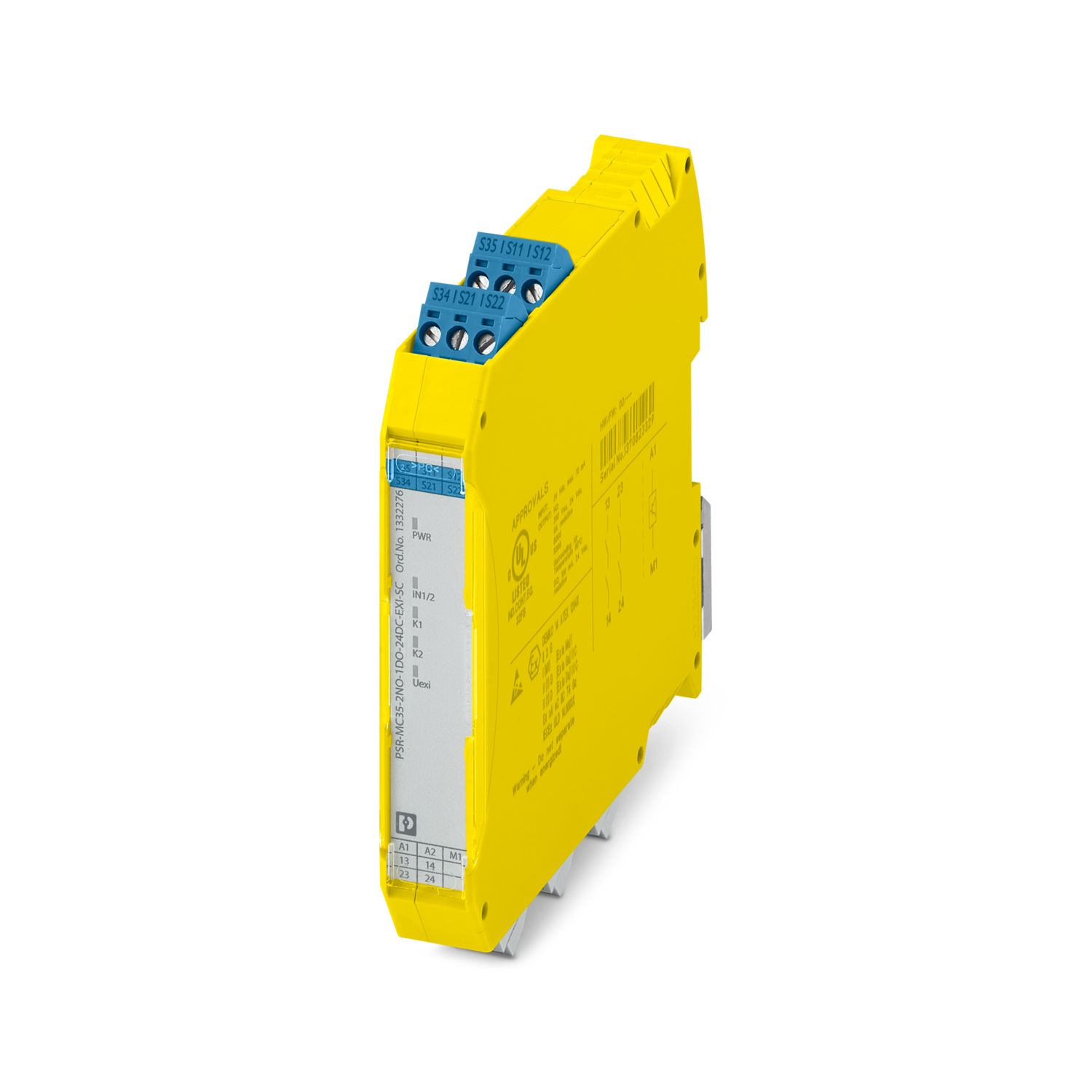
Safety relay for emergency stop switch up to SIL 3, Cat. 4, PL e, 2 intrinsically safe inputs up to zone 0, 2 enabling current paths, automatic or manual, monitored start, plug-in screw terminal block, US = 24 V DC
Product details
| Product type | Safety relays |
| Product family | PSRmini |
| Relay type | Electromechanical relay with force-guided contacts in accordance with IEC/EN 61810-3 |
| Insulation characteristics | |
| Overvoltage category | II |
| Degree of pollution | 2 |
| Times | |
| Typical response time | < 100 ms (manual, monitored start) |
| < 100 ms (automatic start) | |
| Typ. starting time with Us | < 100 ms (when controlled via A1) |
| Typical release time | < 20 ms (on demand via the sensor circuit) |
| < 20 ms (on demand via A1) | |
| Restart time | < 1 s (Boot time, after switching on the supply voltage) |
| Recovery time | 1 s (following demand of the safety function) |
| Start pulse length | ≥ 500 ms (manual start) |
| Maximum power dissipation for nominal condition | 7.82 W (US = 30 V, IREL² = 72 A², UContactVoltageDrop = 0.2 V, PTotal max = 1.42 W + 6.2 W) |
| Nominal operating mode | 100% operating factor |
| Rated insulation voltage | 320 V |
| Rated surge voltage/insulation | See data sheet, section “Insulation coordination”. |
| Supply | |
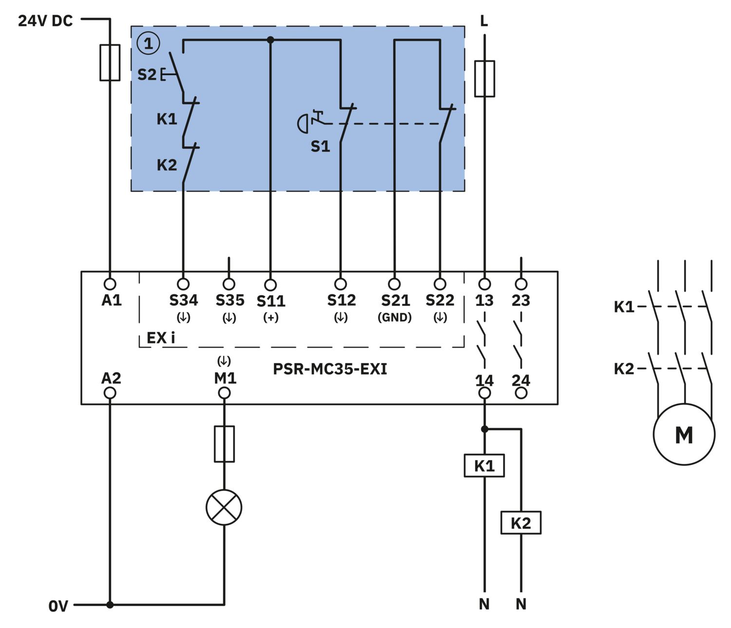
| Designation | A1/A2 |
| Rated control circuit supply voltage US | 19.2 V DC ... 30 V DC |
| Rated control circuit supply voltage US | 24 V DC -20 % / +25 % (provide external protection) |
| Rated control supply current IS | typ. 55 mA |
| Inrush current | typ. 6 A (Δt = 200 s, at US) |
| Filter time | 1 ms (at A1 in the event of voltage dips at Us) |
| Power consumption at UD | typ. 1.32 W |
| Protective circuit | Serial protection against polarity reversal; Suppressor diode |
| Digital: Sensor circuit (S12, S22) | |
| Description of the input | safety-related sensor inputs |
| Number of inputs | 2 |
| Input voltage range "1" signal | 5 V ... 9 V (S12) |
| 1 V ... 2.5 V (S22) | |
| Inrush current | < 4 mA (Δt = 500 µs at Us) |
| Filter time | High test pulses and low test pulses are not permitted |
| Concurrence | ∞ |
| Max. permissible overall conductor resistance | 200 Ω |
| Protective circuit | Suppressor diode |
| Current consumption | < 4 mA (typ. with US) |
| Digital: Start circuit (S34, S35) | |
| Description of the input | non-safety-related |
| NPN | |
| Number of inputs | 2 |
| Input voltage range "1" signal | 5 V ... 9 V |
| Inrush current | < 4 mA (typ. with US, Δt 100 ms) |
| Filter time | High test pulses and low test pulses are not permitted |
| Concurrence | ∞ |
| Max. permissible overall conductor resistance | 200 Ω |
| Protective circuit | Suppressor diode |
| Current consumption | < 4 mA (typ. with US) |
| Relay: Enabling current path (13/14, 23/24) | |
| Output description | 2 N/O contacts each in series, safety-related, floating |
| Number of outputs | 2 (undelayed) |
| Contact switching type | 2 enabling current paths |
| Contact material | AgSnO2 |
| Switching voltage | min. 12 V |
| max. 250 V AC/DC () | |
| Switching capacity | min. 60 mW |
| Inrush current | min. 3 mA |
| max. 6 A | |
| Limiting continuous current | 6 A |
| Sq. Total current | 72 A2 (observe derating) |
| Switching frequency | 0.1 Hz |
| Mechanical service life | 10x 106 cycles |
| Output fuse | 6 A gL/gG |
| 4 A gL/gG (for low-demand applications) | |
| Signal: M1 | |
| Output description | PNP |
| non-safety-related | |
| Number of outputs | 1 |
| Voltage | approx. 22 V DC (Us - 2 V) |
| Current | max. 100 mA |
| Maximum inrush current | 500 mA (Δt = 1 ms at Us) |
| Ohmic load | min. 220 Ω |
| Protective circuit | Suppressor diode |
| Short-circuit protection | Yes |
| Output fuse | ≤ 200 mA (For applications with requirements regarding the “ia” type of protection, see Section “Installation in potentially explosive areas”) |
| Connection technology | |
| pluggable | yes |
| Conductor connection | |
| Connection method | Screw connection |
| Conductor cross-section rigid | 0.2 mm² ... 2.5 mm² |
| Conductor cross-section flexible | 0.2 mm² ... 2.5 mm² |
| Conductor cross-section AWG | 24 ... 12 |
| Stripping length | 7 mm |
| Screw thread | M3 |
| Tightening torque | 0.5 Nm ... 0.6 Nm |
| Safety data: Intrinsically safe connections (S11, S12, S21, S22, S34, S35)/Ex i parameters | |
| Note | Safety characteristics in accordance with ATEX and IECEx (IEC 60079-1) |
| Max. internal inductance Li | negligible |
| Max. internal capacitance Ci | 200 nF |
| Max. output voltage Uo | 11.5 V |
| Max. output current Io | 100 mA |
| Max. output power Po | 285 mW |
| Safety-related maximum voltage Um | 63 V AC |
| 90 V DC | |
| I (simple circuit): Max. external inductivity Lo / Max. external capacitance Co | 0.3 mH / 47.8 µF |
| IIA (simple circuit): Max. external inductivity Lo / Max. external capacitance Co | 0.25 mH / 45.8 µF |
| IIB (simple circuit): Max. external inductivity Lo / Max. external capacitance Co | 0.12 mH / 11 µF |
| IIC (simple circuit): Max. external inductivity Lo / Max. external capacitance Co | 0.03 mH / 1.44 µF |
| Status display | 4 x LED (green) |
| Operating voltage display | 1 x green LED (PWR) |
| Width | 17.5 mm |
| Height | 112.2 mm |
| Depth | 114.5 mm |
| Color (Housing) | yellow (RAL 1018) |
| Housing material | PA |
| Safety data | |
| Stop category | 0 |
| Safety data: EN ISO 13849 | |
| Category | 4 |
| Performance level (PL) | e (2 A AC15, 8760 switching cycles/year; 4 A DC13, 8760 switching cycles/year) |
| Safety data: IEC 61508 - High demand | |
| Safety Integrity Level (SIL) | 3 |
| Safety data: IEC 61508 - Low demand | |
| Safety Integrity Level (SIL) | 3 |
| Safety data: EN IEC 62061 | |
| Safety Integrity Level (SIL) | 3 |
| Ambient conditions | |
| Degree of protection | IP20 |
| Min. degree of protection of inst. location | IP54 |
| Ambient temperature (operation) | -20 °C ... 60 °C (observe derating) |
| Ambient temperature (storage/transport) | -40 °C ... 85 °C |
| Maximum altitude | ≤ 2000 m (Above sea level) |
| Max. permissible humidity (storage/transport) | 75 % (on average, 85% infrequently, non-condensing) |
| Max. permissible relative humidity (operation) | 75 % (on average, 85% infrequently, non-condensing) |
| Shock | 15g |
| Vibration (operation) | 10 Hz ... 150 Hz, amplitude 0.15 mm, 2g |
| ATEX | |
| Identification | II 3(1) G Ex ec nC [ia Ga] IIC T4 Gc |
| II (1) G [Ex ia Ga] IIC | |
| II (1) D [Ex ia Da] IIIC | |
| I (M1) [Ex ia Ma] I | |
| Certificate | UL 24 ATEX 3081X |
| IECEx | |
| Identification | Ex ec nC [ia Ga] IIC T4 Gc |
| [Ex ia Ga] IIC | |
| [Ex ia Da] IIIC | |
| [Ex ia Ma] I | |
| Certificate | IECEx ULD 24.0024X |
| UL, USA/Canada | |
| Identification | cULus |
| Certificate | E140324 |
| UL, USA/Canada | |
| Identification | Class I, Zone 2, AEx ec nC IIC T4 |
| Class I, Zone 2, Ex ec nC IIC Gc T4 X | |
| Certificate | E360692 |
| CE | |
| Identification | CE-compliant |
| Mounting type | DIN rail mounting |
| Assembly note | See derating curve |
| Mounting position | vertical or horizontal |
| Item number | 1332276 |
| Packing unit | 1 pc |
| Minimum order quantity | 1 pc |
| Product key | DNA181 |
| GTIN | 4063151630003 |
| Weight per piece (including packing) | 238,3 g |
| Weight per piece (excluding packing) | 155 g |
| Country of origin | DE |
ECLASS
| ECLASS-13.0 | 27371819 |
| ECLASS-15.0 | 27371819 |
| ECLASS-15.0 ASSET | 27250101 |
ETIM
| ETIM 9.0 | EC001449 |
| EU RoHS | |
| Fulfills EU RoHS substance requirements | Yes |
| Exemption | 7(a), 7(c)-I |
| China RoHS | |
| Environment friendly use period (EFUP) |
EFUP-50
An article-related China RoHS declaration table can be found in the download area for the respective article under "Manufacturer declaration". For all articles with EFUP-E, no China RoHS declaration table issued and required.
|
| EU REACH SVHC | |
| REACH candidate substance (CAS No.) | Lead (CAS: 7439-92-1) |
Compatible products
Your advantages
Extended temperature range of up to 70°C
Suitable up to category 4, PL e (EN ISO 13849-1), SIL 3 (EN IEC 62061)
Housing width: 17.5 mm
PHOENIX CONTACT (Pty) Ltd.
36 Lyn Road P.O. Box 916 ZA-Ferndale 2160