
FRONT 2,5-V/SA10- 3 BK NZB80-1
-
PCB terminal block
1711049
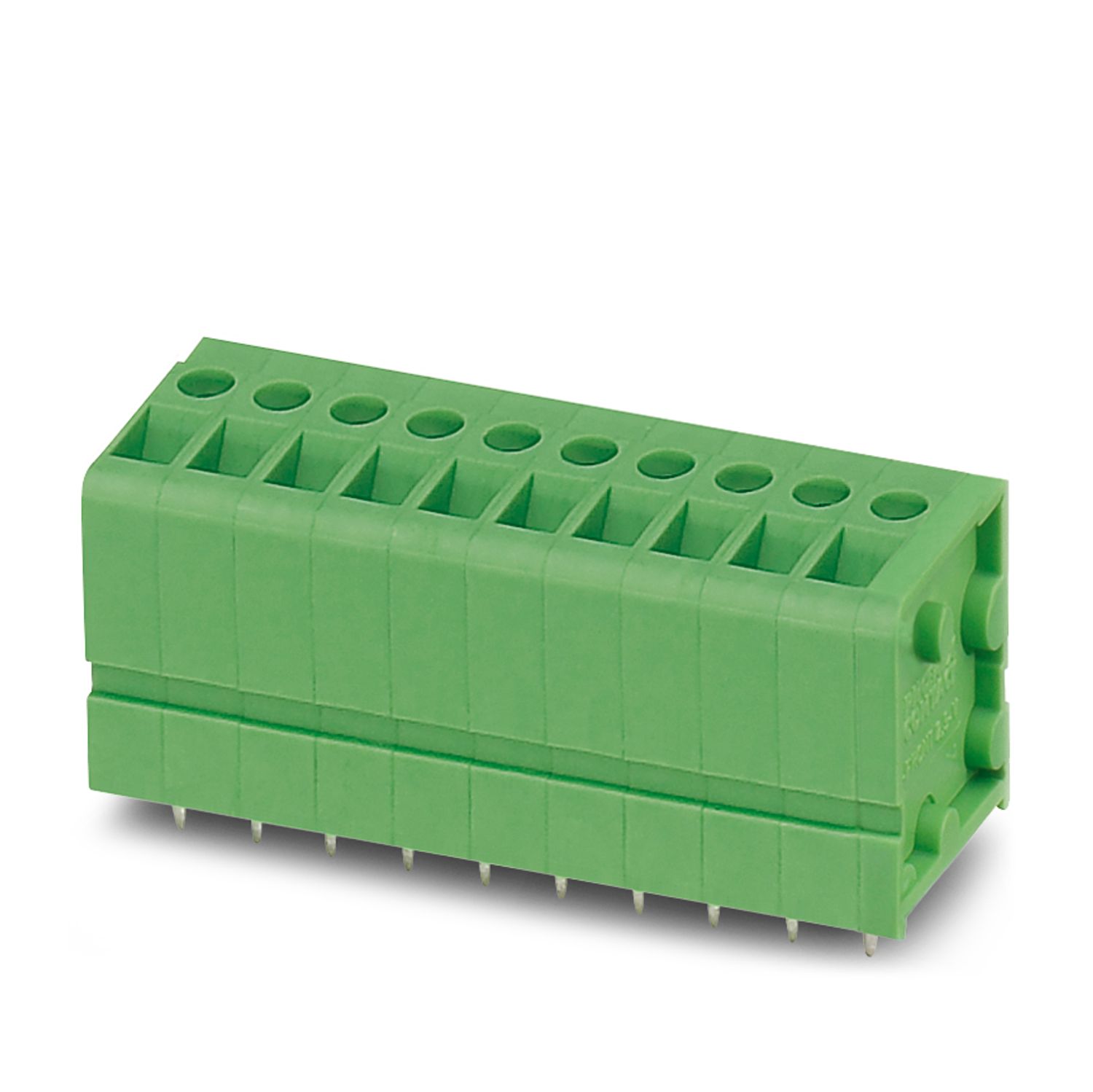
Printed circuit board terminal, nominal current: 24 A, rated voltage (III/2): 400 V, nominal cross section: 2.5 mm2, number of potentials: 3, number of rows: 1, number of positions per row: 3, product range: FRONT 2,5-V/SA10, pitch: 5 mm, connection method: Front screw connection, mounting: Wave soldering, conductor/PCB connection direction: 90 °, color: black, Solder pin [P]: 5 mm, number of solder pins per potential: 2, type of packaging: packed in cardboard
Product details
| Product type | Printed circuit board terminal |
| Product family | FRONT 2,5-V/SA10 |
| Product line | COMBICON Terminals M |
| Number of positions | 3 |
| Pitch | 5 mm |
| Number of connections | 3 |
| Number of rows | 1 |
| Number of potentials | 3 |
| Solder pins per potential | 2 |
| Properties | |
| Nominal current IN | 24 A |
| Nominal voltage UN | 400 V |
| Rated voltage (III/3) | 250 V |
| Rated surge voltage (III/3) | 4 kV |
| Rated voltage (III/2) | 400 V |
| Rated surge voltage (III/2) | 4 kV |
| Rated voltage (II/2) | 630 V |
| Rated surge voltage (II/2) | 4 kV |
| Connection technology | |
| Type | PC terminal block can be aligned |
| Nominal cross section | 2.5 mm² |
| Conductor connection | |
| Connection method | Front screw connection |
| Conductor cross section rigid | 0.2 mm² ... 2.5 mm² |
| Conductor cross section flexible | 0.2 mm² ... 2.5 mm² |
| Conductor cross section AWG | 24 ... 14 |
| Conductor cross section flexible, with ferrule without plastic sleeve | 0.25 mm² ... 1.5 mm² |
| Conductor cross section, flexible, with ferrule, with plastic sleeve | 0.25 mm² ... 1.5 mm² |
| 2 conductors with same cross section, solid | 0.2 mm² ... 0.75 mm² |
| 2 conductors with same cross section, flexible | 0.2 mm² ... 0.75 mm² |
| 2 conductors with same cross section, flexible, with ferrule without plastic sleeve | 0.25 mm² ... 0.34 mm² |
| Stripping length | 9 mm |
| Tightening torque | 0.4 Nm ... 0.5 Nm |
| Mounting type | Wave soldering |
| Material data - contact | |
| Note | WEEE/RoHS-compliant, free of whiskers according to IEC 60068-2-82/JEDEC JESD 201 |
| Contact material | Cu alloy |
| Surface characteristics | hot-dip tin-plated |
| Metal surface terminal point (top layer) | Tin (4 - 8 µm Sn) |
| Metal surface soldering area (top layer) | Tin (4 - 8 µm Sn) |
| Material data - housing | |
| Color (Housing) | black (9005) |
| Insulating material | PA |
| Insulating material group | I |
| CTI according to IEC 60112 | 600 |
| Flammability rating according to UL 94 | V0 |
| Glow wire flammability index GWFI according to EN 60695-2-12 | 850 |
| Glow wire ignition temperature GWIT according to EN 60695-2-13 | 775 |
| Temperature for the ball pressure test according to EN 60695-10-2 | 125 °C |
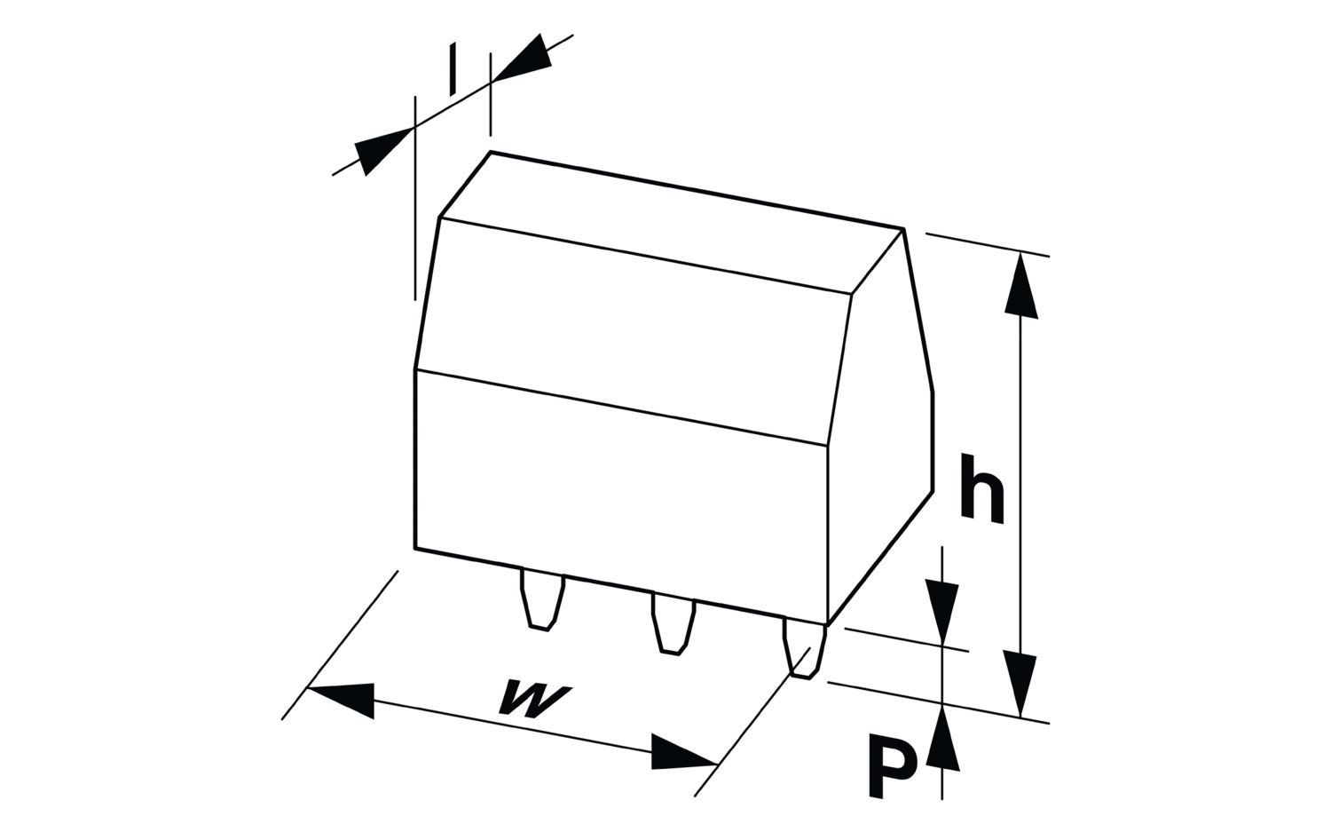
| Dimensional drawing |
|
| Pitch | 5 mm |
| Width [w] | 17.5 mm |
| Height [h] | 24.5 mm |
| Length [l] | 18.5 mm |
| Installed height | 19.5 mm |
| Solder pin length [P] | 5 mm |
| Pin dimensions | 0.8 x 0.8 mm |
| PCB design | |
| Hole diameter | 1.2 mm |
| Test for conductor damage and slackening | |
| Specification | IEC 60999-1:1999-11 |
| Result | Test passed |
| Pull-out test | |
| Specification | IEC 60999-1:1999-11 |
| Conductor cross section/conductor type/tractive force setpoint/actual value | 0.2 mm² / solid / > 10 N |
| 0.2 mm² / flexible / > 10 N | |
| 2.5 mm² / solid / > 50 N | |
| 2.5 mm² / flexible / > 50 N | |
| Temperature-rise test | |
| Specification | IEC 60947-7-4:2019-01 |
| Requirement temperature-rise test | The sum of ambient temperature and temperature rise of the PCB terminal block shall not exceed the upper limiting temperature. |
| Short-time withstand current | |
| Specification | IEC 60947-7-4:2019-01 |
| Insulation resistance | |
| Specification | IEC 60512-3-1:2002-02 |
| Insulation resistance, neighboring positions | > 5 MΩ |
| Air clearances and creepage distances | | |
| Specification | IEC 60947-1:2007-06 + A1:2010-12 + A2:2014-09 |
| Insulating material group | I |
| Comparative tracking index (IEC 60112) | CTI 600 |
| Rated insulation voltage (III/3) | 250 V |
| Rated surge voltage (III/3) | 4 kV |
| minimum clearance value - non-homogenous field (III/3) | 3 mm |
| minimum creepage distance (III/3) | 3.2 mm |
| Rated insulation voltage (III/2) | 400 V |
| Rated surge voltage (III/2) | 4 kV |
| minimum clearance value - non-homogenous field (III/2) | 3 mm |
| minimum creepage distance (III/2) | 3 mm |
| Rated insulation voltage (II/2) | 630 V |
| Rated surge voltage (II/2) | 4 kV |
| minimum clearance value - non-homogenous field (II/2) | 3 mm |
| minimum creepage distance (II/2) | 3.2 mm |
| Vibration test | |
| Specification | IEC 60068-2-6:2007-12 |
| Frequency | 10 - 150 - 10 Hz |
| Sweep speed | 1 octave/min |
| Amplitude | 0.35 mm (10 Hz ... 60.1 Hz) |
| Acceleration | 5g (60.1 Hz ... 150 Hz) |
| Test duration per axis | 2.5 h |
| Test directions | X-, Y- and Z-axis |
| Glow-wire test | |
| Specification | IEC 60695-2-10:2013-04 |
| Temperature | 850 °C |
| Time of exposure | 5 s |
| Aging | |
| Specification | IEC 60947-7-4:2019-01 |
| Ambient conditions | |
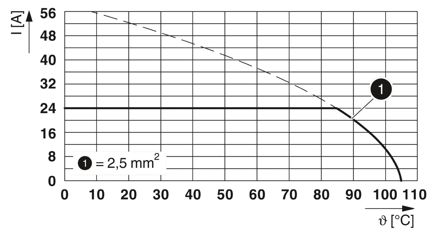
| Ambient temperature (operation) | -40 °C ... 105 °C (Depending on the current carrying capacity/derating curve) |
| Ambient temperature (storage/transport) | -40 °C ... 70 °C |
| Relative humidity (storage/transport) | 30 % ... 70 % |
| Ambient temperature (assembly) | -5 °C ... 100 °C |
| Type of packaging | packed in cardboard |
Your advantages
Well-known connection principle allows worldwide use
Low temperature rise, thanks to maximum contact force
Operation and conductor connection from one direction enable integration into front of device
Two solder pins reduce the mechanical strain on the soldering spots
The latching on the side enables various numbers of positions to be combined
Allows connection of two conductors