
PSR-SCP- 24UC/ESAM4/8X1/1X2
-
Safety relays
2963912
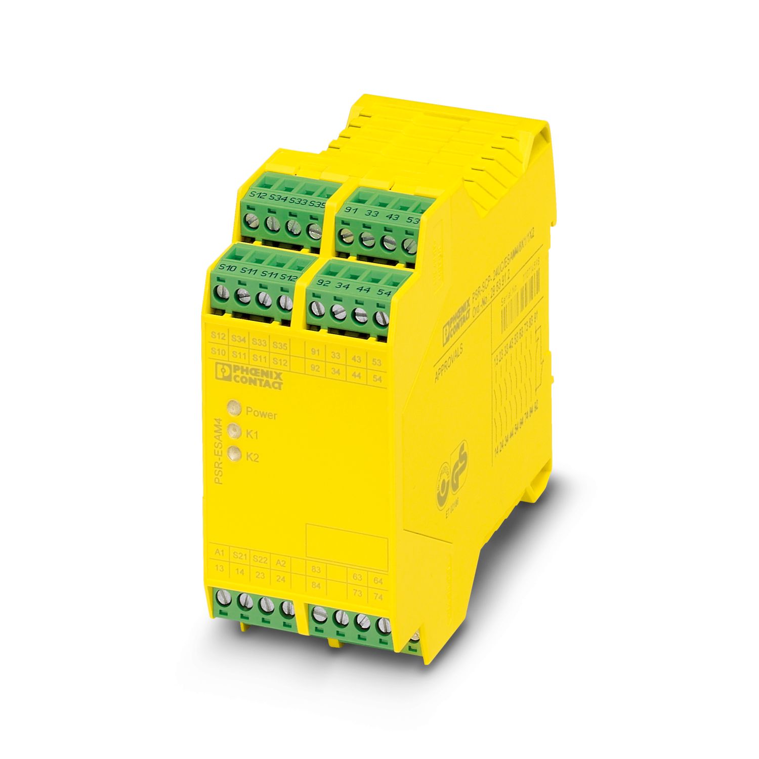
Safety relay for emergency stop and safety door monitoring up to SIL 3 or Cat. 4, PL e in accordance with EN ISO 13849, 1- or 2-channel operation, 8 enabling current paths, US = 24 V DC, plug-in screw terminal block
Free download available.
Downloads
Product details

Your advantages
Up to Cat. 4/PL e in accordance with EN ISO 13849-1, SIL 3 in accordance with EN IEC 62061, SIL 3 in accordance with IEC 61508
Manually monitored and automatic activation in a single device
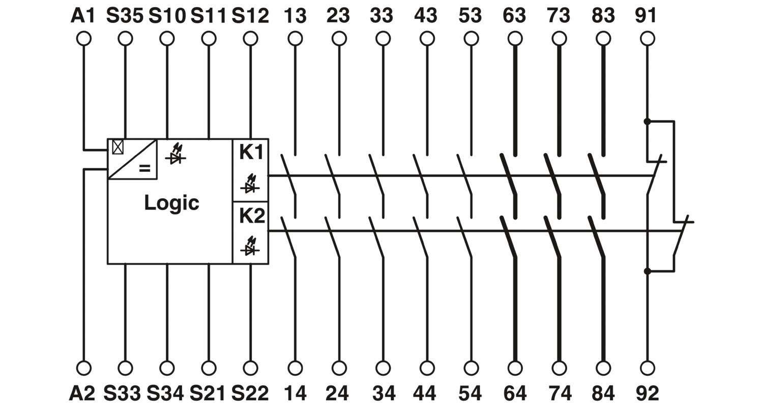
1- and 2-channel control
8 enabling current paths, 1 signaling current path