
PSR-MS21-1NO-1DO-24DC-SC
-
Safety relays
2702192
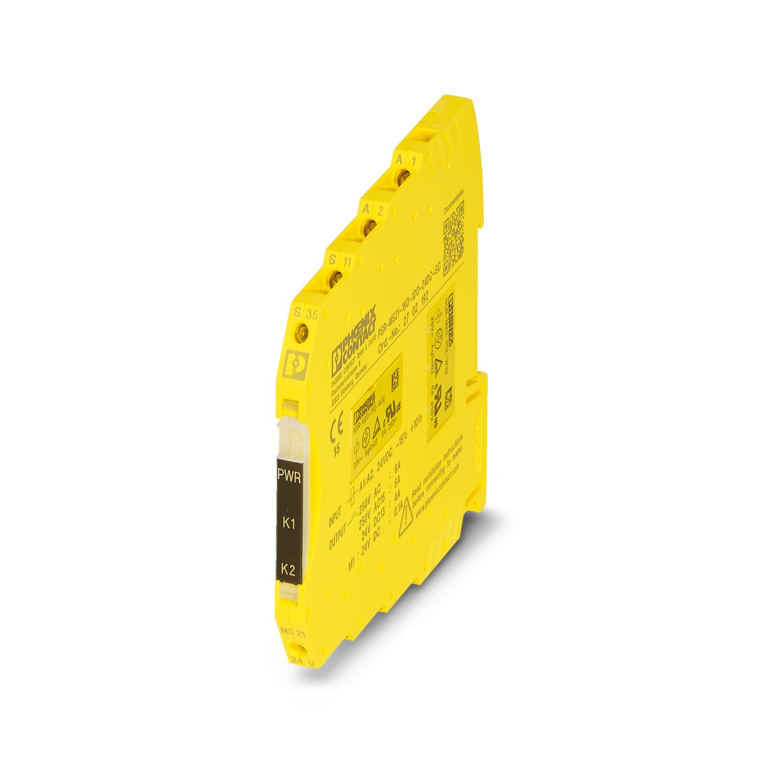
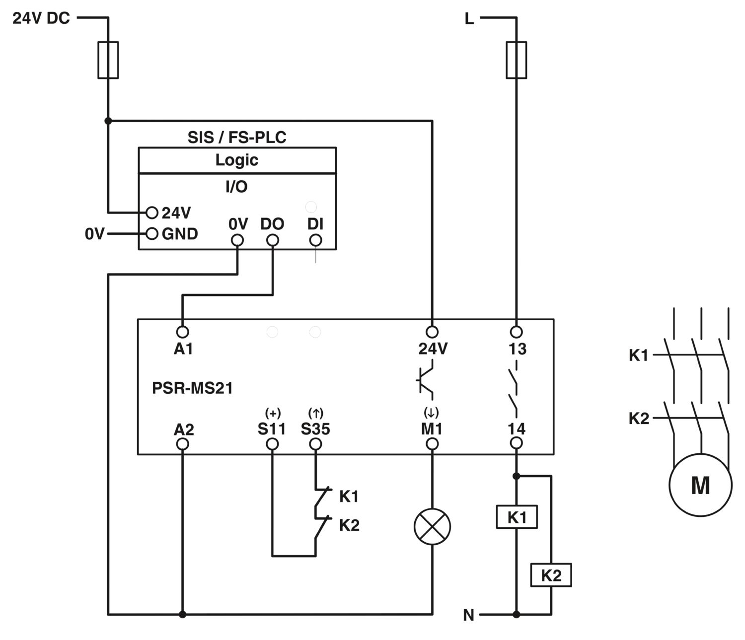
Safety relay for failsafe controllers up to SIL 3, Cat. 4, PL e, 1-channel operation, autostart, 1 enabling current path, US = 24 V DC in accordance with IEC 61131-6, fixed screw terminal block
Free download available.
Downloads
Product details
| Note on application | |
| Note on application | Only for industrial use |
| Product type | Safety relays |
| Product family | PSRmini |
| Application | Controllers |
| Control | 1-channel |
| Relay type | Electromechanical relay with force-guided contacts in accordance with IEC/EN 61810-3 |
| Insulation characteristics | |
| Overvoltage category | III |
| Degree of pollution | 2 |
| Times | |
| Typical response time | < 150 ms (automatic start) |
| Typ. starting time with Us | < 250 ms (when controlled via A1) |
| Typical release time | < 20 ms (when controlled via A1) |
| Restart time | < 1 s (Boot time, after switching on the supply voltage) |
| Recovery time | < 500 ms (following demand of the safety function) |
| Maximum power dissipation for nominal condition | 3.1 W (US = 30 V, IL² = 36A², PTotal max = 1.3 W + +1.8 W) |
| Nominal operating mode | 100% operating factor |
| Rated insulation voltage | 250 V AC |
| Rated surge voltage/insulation | Safe isolation, reinforced insulation 6 kV between input circuit and enabling current path (13/14) Basic insulation 4 kV between all current paths and housing |
| Supply | |
| Designation | 24V |
| Rated control circuit supply voltage US | 24 V DC -20 % / +25 % |
| Inrush current | < 11.5 A (typ. with US, Δt = 25 ns) |
| Protective circuit | Serial protection against polarity reversal; Suppressor diode |
| Short-circuit protection | |
| Digital: A1 | |
| Description of the input | NPN |
| Number of inputs | 1 (safety-related) |
| Input voltage range "0" signal | 0 V DC ... 5 V DC |
| Input voltage range "1" signal | 19.2 V ... 30 V |
| Input current range "0" signal | 0 mA ... 2 mA |
| Inrush current | < 150 mA (typ. with US, Δt = 25 ns) |
| Filter time | 3 ms (Test pulse width of low test pulses) |
| 1 s (Test pulse rate for low test pulse) | |
| 1 ms (Test pulse width, high test pulse) | |
| 100 ms (Test pulse rate, high test pulse) | |
| Unless switch-on pulses/light tests are safety-related, they should be disabled. | |
| Max. permissible overall conductor resistance | 150 Ω (Input and start circuits at US) |
| Protective circuit | Suppressor diode |
| Current consumption | typ. 35 mA (at 24 V) |
| Digital: Start circuit (S35) | |
| Description of the input | NPN |
| Number of inputs | 1 (non-safety-related) |
| Input voltage range "1" signal | 20.4 V ... 26.4 V |
| Inrush current | < 10 mA |
| Max. permissible overall conductor resistance | 150 Ω |
| Voltage at input/start and feedback circuit | 24 V DC -20 % / +25 % |
| Current consumption | < 10 mA |
| Relay: Enabling current path (13/14) | |
| Output description | 2 N/O contacts each in series, safety-related, floating |
| Number of outputs | 1 (undelayed) |
| Contact switching type | 1 enabling current path |
| Contact material | AgSnO2 |
| Switching voltage | min. 12 V AC/DC |
| max. 250 V AC/DC | |
| Switching capacity | min. 60 mW |
| Inrush current | min. 3 mA |
| max. 6 A | |
| Limiting continuous current | 6 A |
| Sq. Total current | 36 A2 (observe derating) |
| Switching frequency | max. 0.1 Hz |
| Mechanical service life | 10x 106 cycles |
| Output fuse | 6 A gL/gG |
| 4 A gL/gG (for low-demand applications) | |
| Signal: M1 | |
| Output description | non-safety-related |
| Number of outputs | 1 (digital, PNP) |
| Voltage | 22 V DC (Us - 2 V DC) |
| Current | max. 100 mA |
| Maximum inrush current | 500 mA (Δt = 1 ms at Us) |
| Protective circuit | Suppressor diode |
| Connection technology | |
| pluggable | no |
| Conductor connection | |
| Connection method | Screw connection |
| Conductor cross section rigid | 0.2 mm² ... 2.5 mm² |
| Conductor cross section flexible | 0.2 mm² ... 2.5 mm² |
| Conductor cross-section AWG | 26 ... 12 |
| Stripping length | 12 mm |
| Screw thread | M3 |
| Tightening torque | 0.5 Nm ... 0.6 Nm |
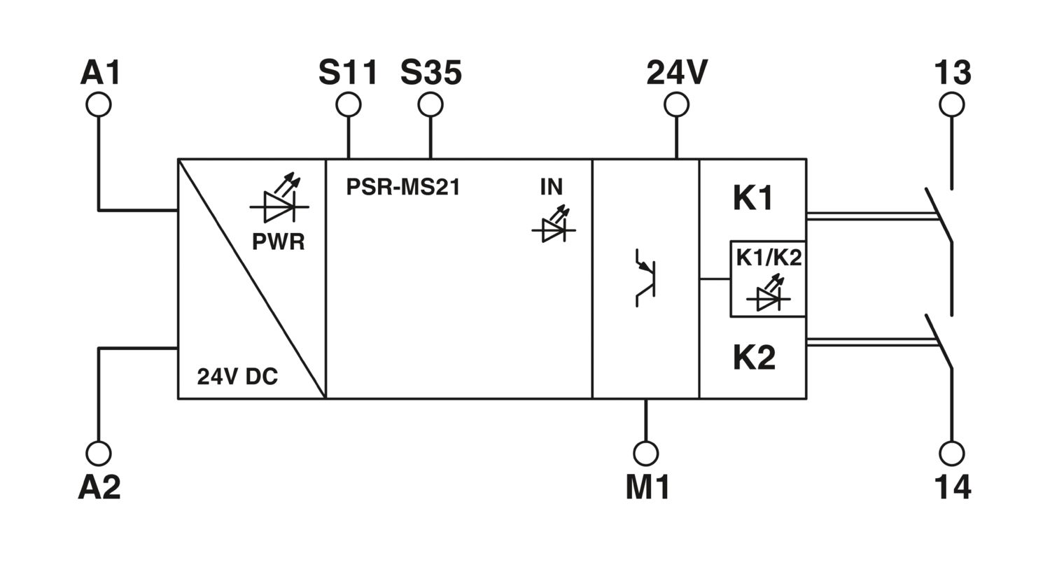
| Status display | 2 x LED (green) |
| Operating voltage display | 1 x LED (green) |
| Width | 6.8 mm |
| Height | 93.1 mm |
| Depth | 102.5 mm |
| Color (Housing) | yellow (RAL 1018) |
| Housing material | PBT |
| Safety data | |
| Stop category | 0 |
| Safety data: EN ISO 13849 | |
| Category | 4 |
| Performance level (PL) | e (4 A DC13; 5 A AC15; 8760 switching cycles/year) |
| Safety data: IEC 61508 - High demand | |
| Safety Integrity Level (SIL) | 3 (4 A DC13; 5 A AC15; 8760 switching cycles/year) |
| Safety data: IEC 61508 - Low demand | |
| Safety Integrity Level (SIL) | 3 |
| Safety data: EN IEC 62061 | |
| Safety Integrity Level (SIL) | 3 (4 A DC13; 5 A AC15; 8760 switching cycles/year) |
| Ambient conditions | |
| Degree of protection | IP20 |
| Min. degree of protection of inst. location | IP54 |
| Ambient temperature (operation) | -40 °C ... 60 °C (observe derating) |
| Ambient temperature (storage/transport) | -40 °C ... 85 °C |
| Maximum altitude | ≤ 2000 m (Above sea level) |
| Max. permissible humidity (storage/transport) | 75 % (on average, 85% infrequently, non-condensing) |
| Max. permissible relative humidity (operation) | 75 % (on average, 85% infrequently, non-condensing) |
| Shock | 15g |
| Vibration (operation) | 10 Hz ... 150 Hz, amplitude 0.15 mm, 2g |
| CE | |
| Certificate | CE-compliant |
| Mounting type | DIN rail mounting |
| Assembly note | See derating curve |
| Mounting position | vertical or horizontal |
| Item number | 2702192 |
| Packing unit | 1 pc |
| Minimum order quantity | 1 pc |
| Sales key | DN01 |
| Product key | DNA171 |
| Catalog page | Page 219 (C-6-2019) |
| GTIN | 4055626010199 |
| Weight per piece (including packing) | 83.4 g |
| Weight per piece (excluding packing) | 69 g |
| Customs tariff number | 85371098 |
| Country of origin | DE |
ECLASS
| ECLASS-13.0 | 27371819 |
ETIM
| ETIM 9.0 | EC001449 |
UNSPSC
| UNSPSC 21.0 | 39122200 |
| EU RoHS | |
| Fulfills EU RoHS substance requirements | Yes |
| Exemption | 7(a), 7(c)-I |
| China RoHS | |
| Environment friendly use period (EFUP) |
EFUP-50
An article-related China RoHS declaration table can be found in the download area for the respective article under "Manufacturer declaration". For all articles with EFUP-E, no China RoHS declaration table issued and required.
|
| EU REACH SVHC | |
| REACH candidate substance (CAS No.) | Lead (CAS: 7439-92-1) |
| SCIP | d482e8c4-47b3-4f50-a5f5-17993ad7e57b |
Compatible products

Your advantages
Up to Cat. 4/PL e in accordance with EN ISO 13849-1, SIL 3 in accordance with EN IEC 62061
Low housing width of just 6.8 mm
1-channel control
1 enabling current path, 1 digital signal output
Couples digital output signals from failsafe controllers to I/O devices (valves, etc.) for electrical isolation and power adaptation
Automatic activation
PHOENIX CONTACT
586 Fulling Mill Road, Middletown, PA 17057