The figure shows a version with a screw connection
Key: 1 = Current limitation 2 = Input circuit 3 = Voltage limitation 4 = Start circuit 5 = Control circuit channel 1 6 = Control circuit signal output 7 = Control circuit channel 2 8 = Start channel 1 and 2 9 = Channel 1 10 = Diagnostics K1, K2 ... K4 = Force-guided elementary relays
Safety relays - PSR-MC30-2NO-1DO-24DC-SP
2700499
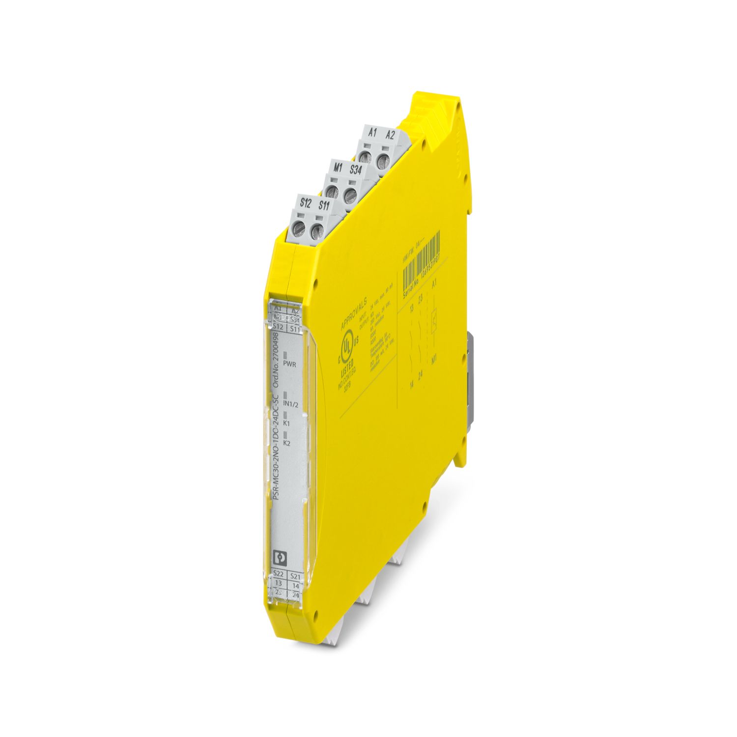
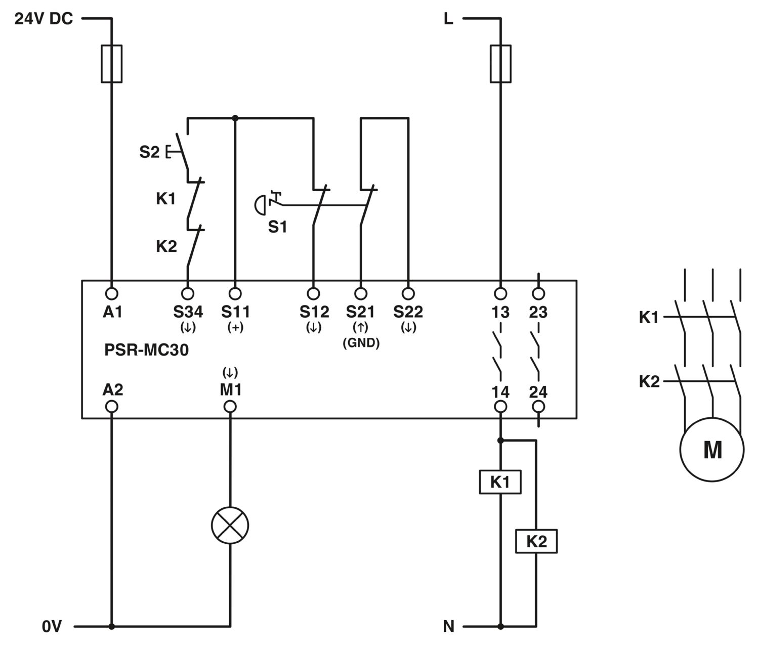
Safety relay for emergency stop and safety doors up to SIL 3, Cat. 4, PL e, 1- or 2-channel operation, automatic or manual, monitored start, cross-circuit detection, 2 enabling current paths, US = 24 V DC, plug-in Push-in terminal block
Electromechanical relay with force-guided contacts in accordance with IEC/EN 61810-3
Insulation characteristics
Overvoltage category
III
Times
Typical response time
< 175 ms (automatic start)
< 175 ms (manual, monitored start)
Typ. starting time with Us
< 250 ms (when controlled via A1)
Typical release time
< 20 ms (when controlled via A1 or S12 and S22.)
Recovery time
< 500 ms
Nominal operating mode
100% operating factor
Designation
A1/A2
Rated control circuit supply voltage US
20.4 V DC ... 26.4 V DC
Rated control circuit supply voltage US
24 V DC -15 % / +10 %
Rated control supply current IS
typ. 65 mA
Power consumption at US
typ. 1.56 W
Inrush current
4 A (Δt = 200 µs at Us)
Filter time
1 ms (at A1 in the event of voltage dips at Us)
Protective circuit
Surge protection; Suppressor diode
Protection against polarity reversal for rated control circuit supply voltage
Rated insulation voltage
250 V AC
Rated insulation voltage
250 V AC
Rated surge voltage/insulation
Safe isolation, reinforced insulation 6 kV between input circuit and enabling current path (13/14) and enabling current path (23/24) Basic insulation 4 kV between all current paths and housing
Digital: Sensor circuit (S11, S12, S21, S22)
Description of the input
safety-related sensor inputs
Input voltage range "0" signal
0 V DC ... 5 V DC (for safe Off; at S12)
Input current range "0" signal
0 mA ... 2 mA (for safe Off; at S12)
Inrush current
< 20 mA (with Us/Ix to S12)
< 5 mA (with Us/Ix to S22)
> -15 mA (with Us/Ix to S22/S21)
Filter time
max. 1.5 ms (at S12, S22; test pulse width)
min. 7.5 ms (at S12, S22; test pulse rate)
Test pulse rate = 5 x Test pulse width
Max. permissible overall conductor resistance
150 Ω
Current consumption
< 5 mA (with Us/Ix to S12)
< 5 mA (with Us/Ix to S22)
> -5 mA (with Us/Ix to S22/S21)
Digital: Start circuit (S34)
Description of the input
non-safety-related
Number of inputs
1
Input voltage range "1" signal
20.4 V DC ... 26.4 V DC
Inrush current
typ. 200 mA
Max. permissible overall conductor resistance
150 Ω
Protective circuit
Suppressor diode
Current consumption
< 10 mA (at S34/24 V)
> -5 mA (at S34/0 V)
Relay: Enabling current paths (13/14, 23/24)
Output description
safety-related N/O contacts
Number of outputs
2 (undelayed)
Contact type
2 enabling current paths
Contact material
AgSnO2
Switching voltage
min. 12 V AC/DC
max. 250 V AC/DC (Observe the load curve)
Switching capacity
min. 60 mW
Inrush current
min. 3 mA
max. 6 A
Limiting continuous current
6 A (observe derating)
Sq. Total current
72 A2 (observe derating)
Switching frequency
0.5 Hz
Mechanical service life
10x 106 cycles
Output fuse
6 A gL/gG (N/O contact)
4 A gL/gG (for low-demand applications)
Signal: M1
Output description
non-safety-related
Number of outputs
1 (digital, PNP)
Voltage
22 V DC (Us - 2 V)
Current
max. 100 mA
Maximum inrush current
500 mA (Δt = 1 ms at Us)
Short-circuit protection
no
Connection technology
pluggable
yes
Conductor connection
Connection method
Push-in connection
Conductor cross section solid
0.2 mm² ... 1.5 mm²
Conductor cross section flexible, with ferrule without plastic sleeve
0.25 mm² ... 1.5 mm² (only together with CRIMPFOX 6)
Conductor cross-section AWG
24 ... 16
Status display
3 x green LED
Operating voltage display
1 x green LED
Width
12.5 mm
Height
116.6 mm
Depth
114.5 mm
Housing material
Polyamide
Housing color
yellow
Safety data
Stop category
0
Safety data: EN ISO 13849
Category
4
Performance level (PL)
e (4 A DC13; 5 A AC15; 8760 switching cycles/year)
Safety data: IEC 61508 - High demand
Safety Integrity Level (SIL)
3
Probability of a hazardous failure per hour (PFHD)
1.5 x 10⁻⁹ (4 A DC13; 5 A AC15; 8760 switching cycles/year)
Proof test interval
240 Months
Duration of use
240 Months
Safety data: IEC 61508 - Low demand
Safety Integrity Level (SIL)
3
Probability of a hazardous failure on demand (PFDAVG)
1.47 x 10⁻⁴
Proof test interval
60 Months
Duration of use
240 Months
Ambient conditions
Degree of protection
IP20
Min. degree of protection of inst. location
IP54
Ambient temperature (operation)
-40 °C ... 55 °C (observe derating)
Ambient temperature (storage/transport)
-40 °C ... 85 °C
Maximum altitude
≤ 2000 m (Above sea level)
Max. permissible humidity (storage/transport)
75 % (on average, 85% infrequently, non-condensing)
Max. permissible relative humidity (operation)
75 % (on average, 85% infrequently, non-condensing)
Shock
15g
Vibration (operation)
10 Hz ... 150 Hz, 2g
Air clearances and creepage distances between the power circuits
Standards/regulations
EN 60664-1
Mounting type
DIN rail mounting
Assembly instructions
See derating curve
Mounting position
vertical or horizontal
Item number
2700499
Packing unit
1 pc
Minimum order quantity
1 pc
Sales Key
C18
Product Key
DNA181
Catalog Page
Page 221 (C-6-2019)
GTIN
4046356912877
Weight per Piece (including packing)
157.25 g
Weight per Piece (excluding packing)
155 g
Customs tariff number
85371098
Country of origin
DE
ECLASS
ECLASS-9.0
27371819
ECLASS-10.0.1
27371819
ECLASS-11.0
27371819
ETIM
ETIM 8.0
EC001449
UNSPSC
UNSPSC 21.0
39122200
EAC
Approval ID: RU C-DE.A*30.B.01082
DNV GL
Approval ID: TAA00002VZ
UL Listed
Approval ID: FILE E 140324
cUL Listed
Approval ID: FILE E 140324
Functional Safety
Approval ID: 44-205-13755201
Functional Safety
Approval ID: 44-780-13755201
cULus Listed
REACh SVHC
Lead 7439-92-1
China RoHS
Environmentally Friendly Use Period = 50 years
For information on hazardous substances, refer to the manufacturer’s declaration available under “Downloads”
Your advantages
Up to Cat. 4/PL e in accordance with EN ISO 13849-1, SIL 3 in accordance with IEC 62061
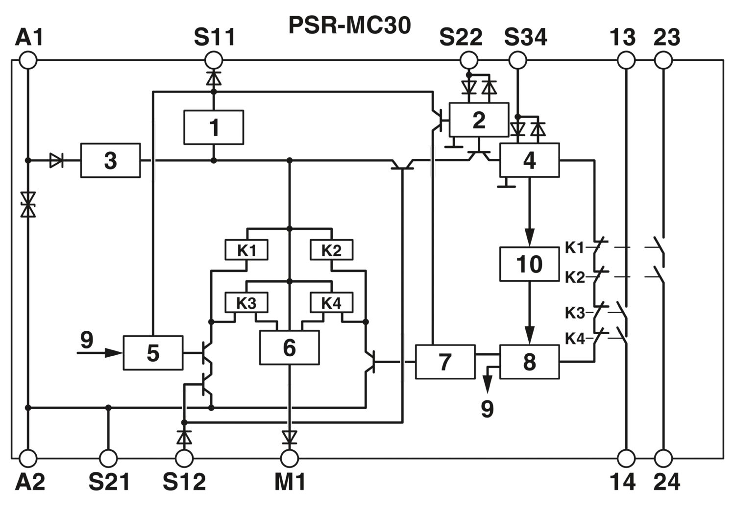
Cross-circuit detection
Low housing width of just 12.5 mm
Manually monitored and automatic activation in a single device
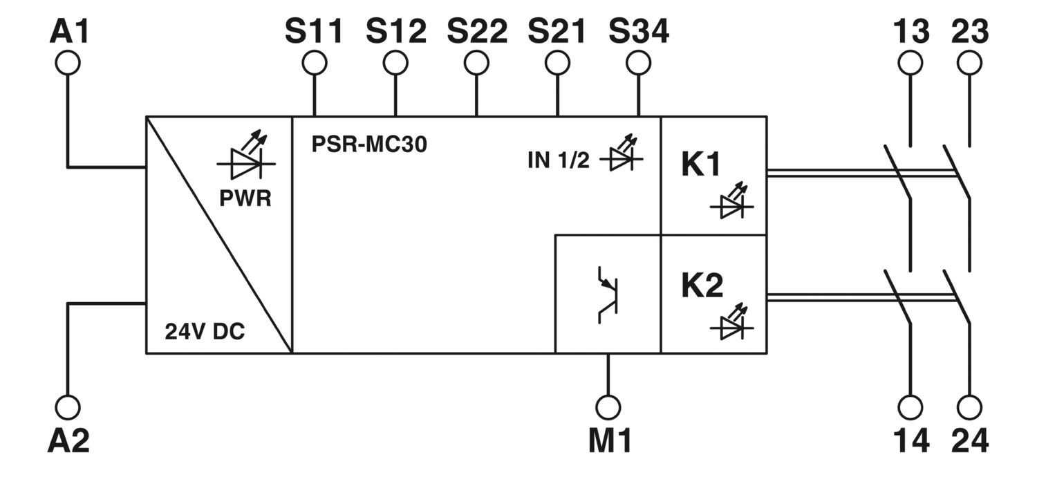