
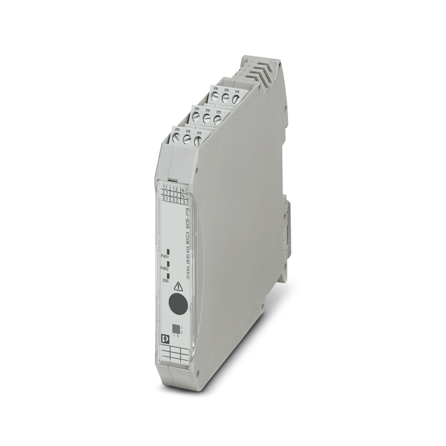
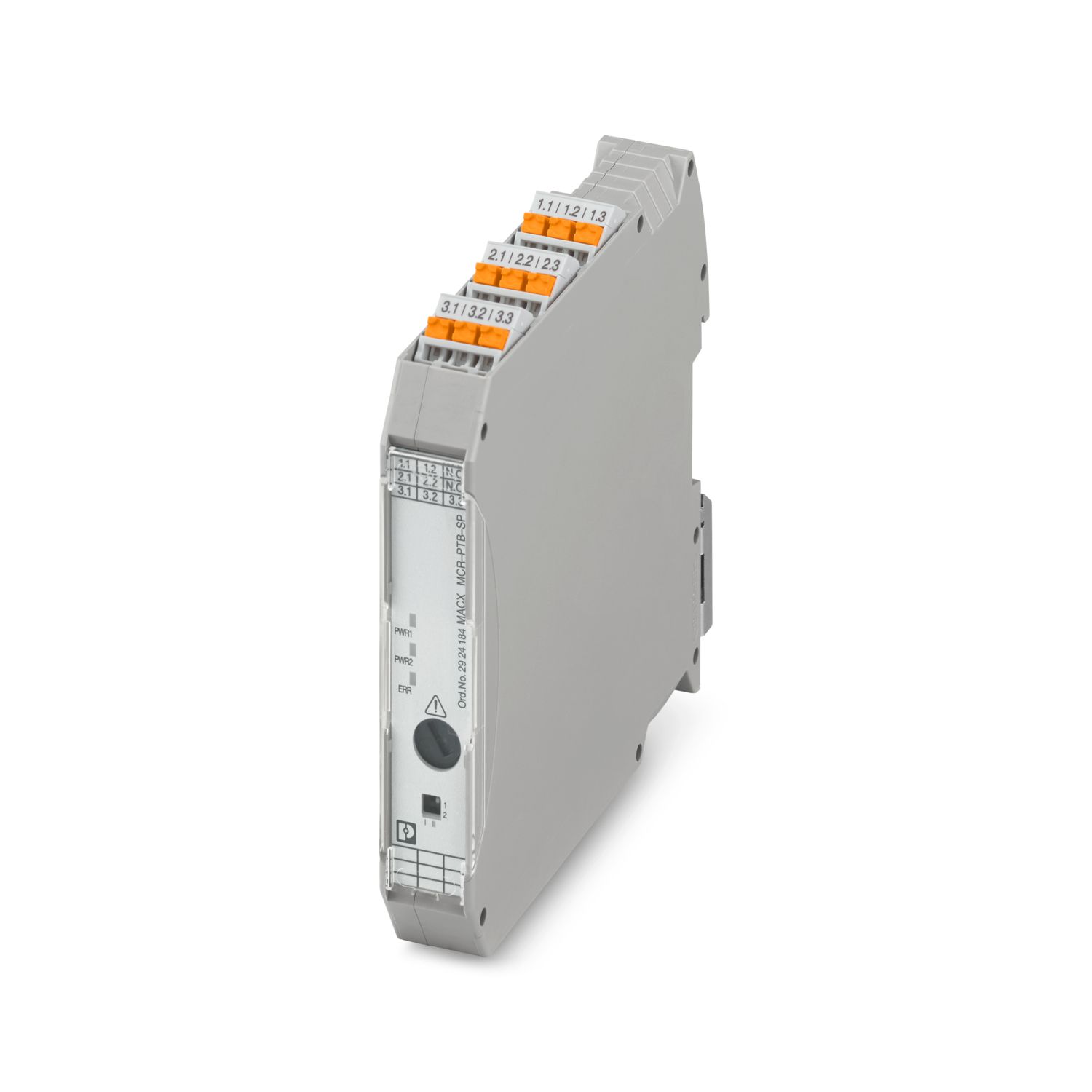
MACX MCR-SL-RPSSI-I-SP
-
Power/input signal conditioner
2924207
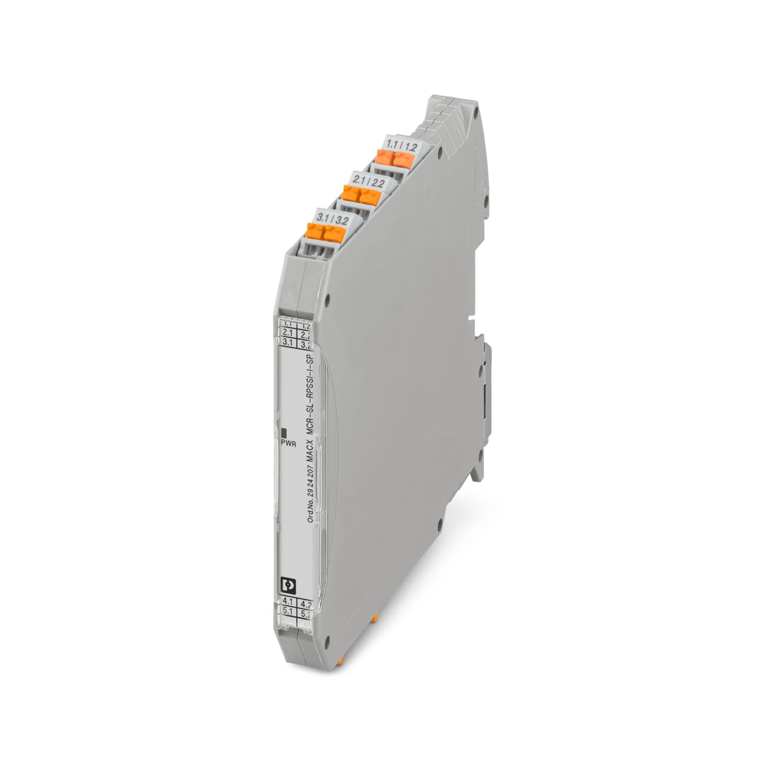
Repeater power supply and input signal conditioner, HART-transparent. Transmits supplied or active 0/4 … 20 mA signals to a load (active or passive). 3-way electrical isolation, SIL 2 in accordance with IEC 61508.
Product details
| Product type | Repeater power supply |
| Product family | MACX Analog |
| Application | Analog IN |
| No. of channels | 1 |
| Electrical isolation | 3-way isolation |
| Electrical isolation between input and output | yes |
| Signal transmission behavior | In = Out |
| Step response (10-90%) | < 200 µs (for jump 4 mA ... 20 mA, load 600 Ω) |
| < 600 µs (for jump 0 mA ... 20 mA, load 600 Ω) | |
| Maximum temperature coefficient | < 0.01 %/K |
| Maximum transmission error | < 0.1 % (of final value 20 mA) |
| Transmission error, typical | < 0.05 % (of final value 20 mA) |
| Electrical isolation | |
| Test voltage | 2.5 kV AC (50 Hz, 60 s) |
| Overvoltage category | II |
| Pollution degree | 2 |
| Electrical isolation Input/output/power supply IEC/EN 61010-1 | |
| Standards/regulations | IEC/EN 61010-1 |
| Rated insulation voltage | 300 Vrms |
| Insulation | Safe isolation |
| Electrical isolation Input/output IEC/EN 60079-11 | |
| Standards/regulations | IEC/EN 60079-11 |
| Rated insulation voltage | 265 Vrms |
| Electrical isolation Input/power supply IEC/EN 60079-11 | |
| Standards/regulations | IEC/EN 60079-11 |
| Rated insulation voltage | 265 Vrms |
| Electrical isolation Output/supply IEC/EN 60079-7 | |
| Standards/regulations | IEC/EN 60079-7 |
| Rated insulation voltage | 265 Vrms |
| Supply | |
| Designation | Repeater power supply operation |
| Nominal supply voltage | 24 V DC -20 % ... +25 % |
| Supply voltage range | 19.2 V DC ... 30 V DC |
| Max. current consumption | < 76 mA (24 V DC / 20 mA / 1000 Ω) |
| < 55 mA (24 V DC / 20 mA / 250 Ω) | |
| Power dissipation | < 1.1 W (24 V DC / 20 mA / 1000 Ω) |
| < 0.95 W (24 V DC / 20 mA / 250 Ω) | |
| < 1.2 W (24 V DC / 20 mA / 0 Ω) | |
| Power consumption (Output active) | < 1.8 W (20 mA / 1000 Ω) |
| < 1.3 W (20 mA / 250 Ω) | |
| Supply | |
| Designation | Signal conditioner operation |
| Nominal supply voltage | 24 V DC -20 % ... +25 % |
| Supply voltage range | 19.2 V DC ... 30 V DC |
| Max. current consumption | < 44 mA (24 V DC / 20 mA / 1000 Ω) |
| < 27 mA (24 V DC / 20 mA / 250 Ω) | |
| Power dissipation | < 0.75 W (24 V DC / 20 mA / 1000 Ω) |
| < 0.65 W (24 V DC / 20 mA / 250 Ω) | |
| < 0.95 W (24 V DC / 20 mA / 0 Ω) | |
| Signal: Repeater power supply operation | |
| Description of the input | Active current input |
| Number of inputs | 1 |
| Input signal | Current |
| Current input signal | 4 mA ... 20 mA |
| Current limitation | 25 mA |
| Transmitter supply voltage | > 21.5 V (20 mA) |
| > 20.8 V (24 mA) | |
| Underload/overload signal range | 0 mA ... 24 mA (Extended transmission range for diagnostics) |
| Signal: Signal conditioner operation | |
| Description of the input | Passive current input |
| Current input signal | 0 mA ... 20 mA |
| 4 mA ... 20 mA | |
| Voltage drop | < 3.5 V (in input isolating amplifier operation) |
| Underload/overload signal range | 0 mA ... 24 mA (Extended transmission range for diagnostics) |
| Signal: Repeater power supply operation | |
| Output description | Current output (active and passive) |
| Number of outputs | 1 |
| Current output signal | 4 mA ... 20 mA (active) |
| 4 mA ... 20 mA (14 ... 26 V ext. source voltage) | |
| Load/output load current output | < 1000 Ω (20 mA) |
| < 825 Ω (24 mA) | |
| Output ripple | < 20 mVrms |
| Output behavior in the event of an error | 0 mA (Cable break in the input) |
| ≥ 22.5 mA (Cable short-circuit in the input) | |
| Underload/overload signal range | 0 mA ... 24 mA (Extended transmission range for diagnostics) |
| Signal: Signal conditioner operation | |
| Output description | Current output (active and passive) |
| Current output signal | 0 mA ... 20 mA (active) |
| 4 mA ... 20 mA (active) | |
| 0 mA ... 20 mA (14 ... 26 V ext. source voltage) | |
| 4 mA ... 20 mA (14 ... 26 V ext. source voltage) | |
| Load/output load current output | < 1000 Ω (20 mA) |
| < 825 Ω (24 mA) | |
| Output ripple | < 20 mVrms |
| Output behavior in the event of an error | 0 mA (Cable break in the input) |
| 0 mA (Cable short-circuit in the input) | |
| Underload/overload signal range | 0 mA ... 24 mA (Extended transmission range for diagnostics) |
| Connection method | Push-in connection |
| Stripping length | 10 mm |
| Conductor cross section rigid | 0.2 mm² ... 2.5 mm² |
| Conductor cross section flexible | 0.2 mm² ... 2.5 mm² |
| Conductor cross section flexible (2 conductors with same cross section) | 0.25 mm² ... 0.34 mm² (TWIN ferrule without plastic sleeve) |
| 0.5 mm² ... 1.5 mm² (TWIN ferrule with plastic sleeve) | |
| Conductor cross section AWG | 24 ... 14 |
| 24 ... 22 (TWIN ferrule without plastic sleeve) | |
| 20 ... 16 (TWIN ferrule with plastic sleeve) |
| Ex installation (EPL) | Gc |
| Div. 2 |
| Data communication (bypass) | |
| HART function | Yes |
| Protocols supported | HART-transparent |
| Status display | Green LED (supply voltage) |
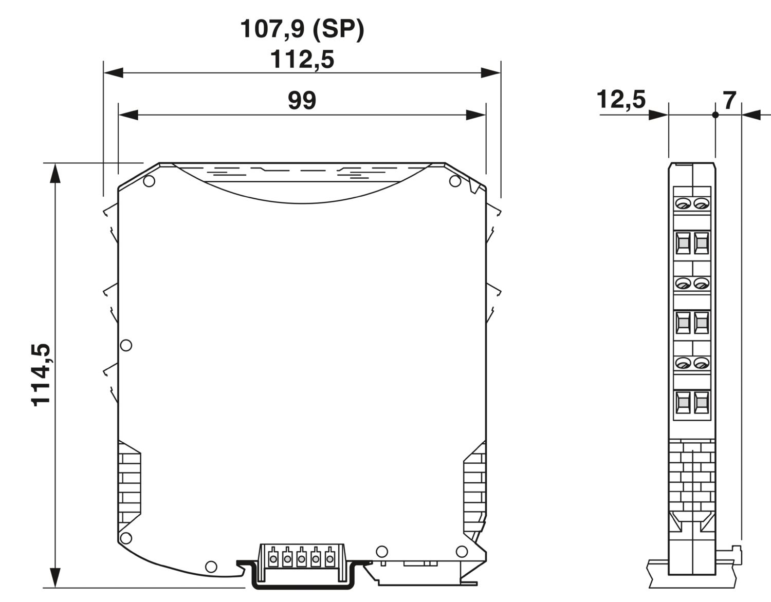
| Dimensional drawing |
|
| Width | 12.5 mm |
| Height | 107.9 mm |
| Depth | 113.7 mm |
| Depth NS 35/7,5 | 114.5 mm (Snapped onto DIN rail NS 35/7,5 in accordance with EN 60715) |
| Color | gray (RAL 7042) |
| Flammability rating according to UL 94 (Housing) | V0 (Housing) |
| Housing material | PA 6.6-FR |
| Ambient conditions | |
| Degree of protection | IP20 (not assessed by UL) |
| Ambient temperature (operation) | -40 °C ... 60 °C (Any mounting position) |
| -40 °C ... 70 °C (Derating) | |
| Ambient temperature (storage/transport) | -40 °C ... 80 °C |
| Permissible humidity (operation) | 10 % ... 95 % (non-condensing) |
| Altitude range (≤ 2000 m) | |
| Altitude | ≤ 2000 m (The technical data refers to altitudes ≤2000 m above mean sea level. For altitudes >2000 m above mean sea level, refer to the data sheet.) |
| Ambient temperature (operation) | -40 °C ... 60 °C |
| -40 °C ... 70 °C (Derating) | |
| Rated insulation voltage | 375 VPP (Power supply, input / output) |
| Altitude range (≤ 3000 m) | |
| Height range | > 2000 m ... 3000 m |
| Ambient temperature (operation) | -40 °C ... 54 °C |
| -40 °C ... 63 °C (Derating) | |
| Rated insulation voltage | 190 V AC (Power supply, input / output) |
| 110 V DC (Power supply, input / output) | |
| Altitude range (≤ 4000 m) | |
| Height range | > 3000 m ... 4000 m |
| Ambient temperature (operation) | -40 °C ... 48 °C |
| -40 °C ... 56 °C (Derating) | |
| Rated insulation voltage | 60 V AC/DC (Power supply, input / output) |
| Altitude range (≤ 5000 m) | |
| Height range | > 4000 m ... 5000 m |
| Ambient temperature (operation) | -40 °C ... 42 °C |
| -40 °C ... 49 °C (Derating) | |
| Rated insulation voltage | 60 V AC/DC (Power supply, input / output) |
| CE | |
| Certificate | CE-compliant |
| Note | and EN 61326 |
| ATEX | |
| Identification | II 3 G Ex ec IIC T4 Gc |
| Certificate | PxCIF08ATEX2865955X |
| UKCA Ex (UKEX) | |
| Identification | II 3 G Ex nA IIC T4 Gc X |
| Certificate | PxCIF21UKEX2865955X |
| IECEx | |
| Identification | Ex ec IIC T4 Gc |
| Certificate | IECEx BVS 08.0016X |
| CCC / China-Ex | |
| Identification | Ex ec IIC T4 Gc |
| Certificate | 2022122304115127 |
| UL, USA/Canada | |
| Identification | UL 61010 Listed |
| UL 508 Listed | |
| Class I, Div. 2, Groups A, B, C, D T4 | |
| Class I, Zone 2, Group IIC T4 | |
| Shipbuilding approval | |
| Certificate | DNV GL TAA000020C |
| Safety Integrity Level (SIL, IEC 61508) | |
| Identification | 2 |
| Certificate | IN-AT-AS-MRL-2300149 |
| Systematic Capability | |
| Identification | 3 |
| INMETRO | |
| Identification | Ex ec IIC T4 Gc |
| Certificate | DNV 18.0136 X |
| Shipbuilding data | |
| Temperature | B |
| Humidity | B |
| Vibration | A |
| EMC | A |
| Enclosure | Required protection according to the Rules shall be provided upon installation on board |
| Electromagnetic compatibility | Conformance with EMC directive |
| Noise immunity | EN 61000-6-2 |
| Note | When being exposed to interference, there may be minimal deviations. |
| Noise emission | |
| Standards/regulations | EN 61000-6-4 |
| Electrical isolation | 3-way isolation |
| GB Standard | |
| Standards/regulations | GB/T 3836.1 |
| GB/T 3836.3 | |
| Mounting type | DIN rail mounting |


Your advantages
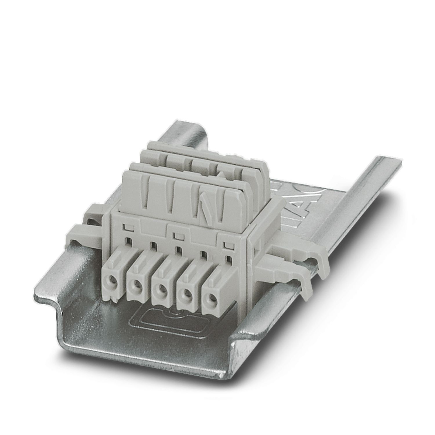
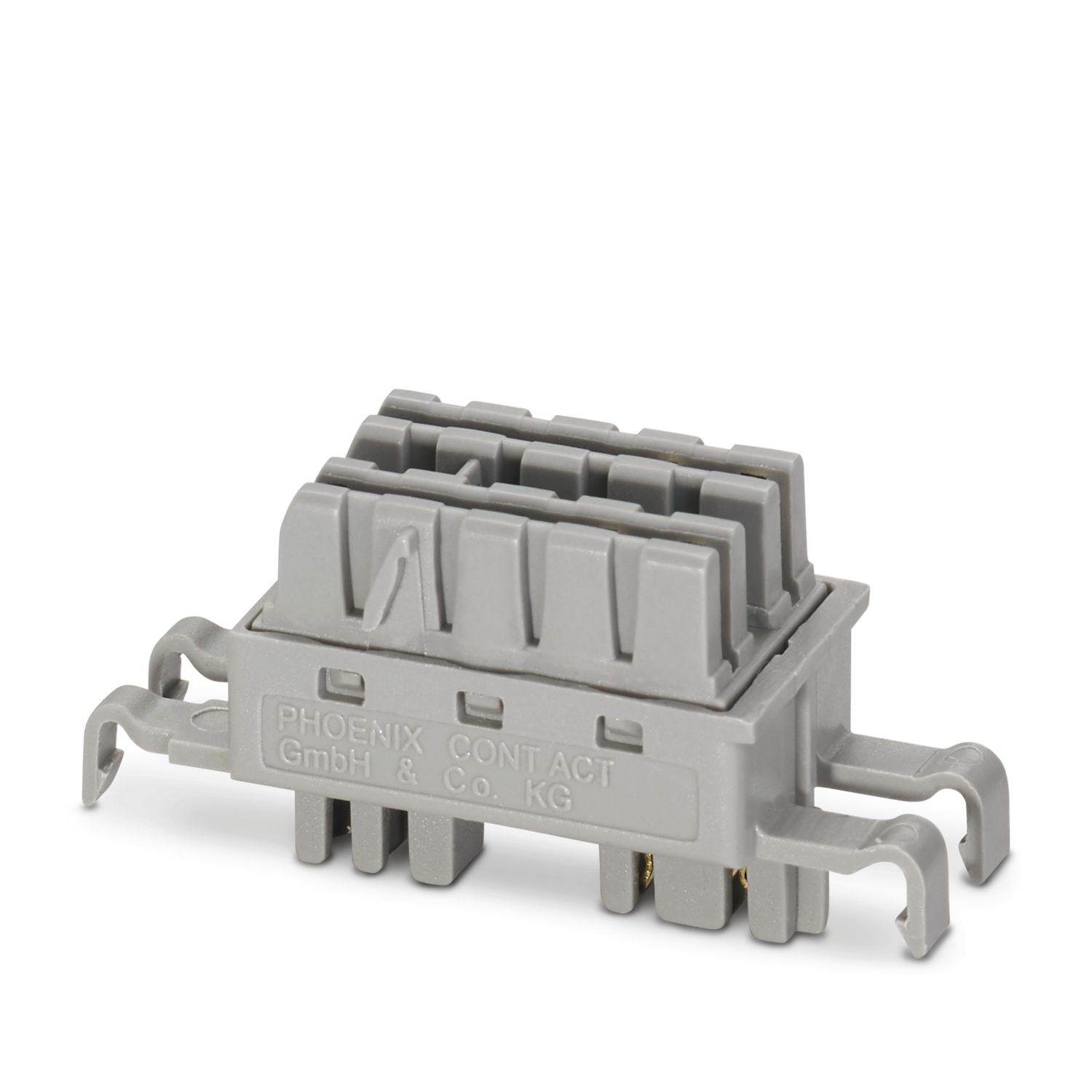
Power supply possible via DIN rail connector
Up to SIL 2 in accordance with EN 61508
Installation in zone 2, protection type "n" (EN 60079-15) permitted
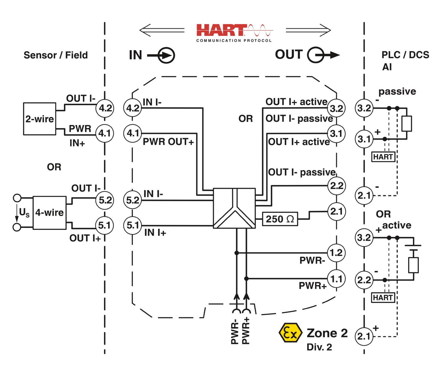
Input: 0/4 mA ... 20 mA (powered or not powered)
Output: 0/4 mA ... 20 mA (active or passive)
Terminal point with 250 Ω resistor to increase HART impedance for low-resistance systems
3-way electrical isolation
Plug-in screw or spring-cage connection technology (Push-in technology), with integrated sockets for HART communicators
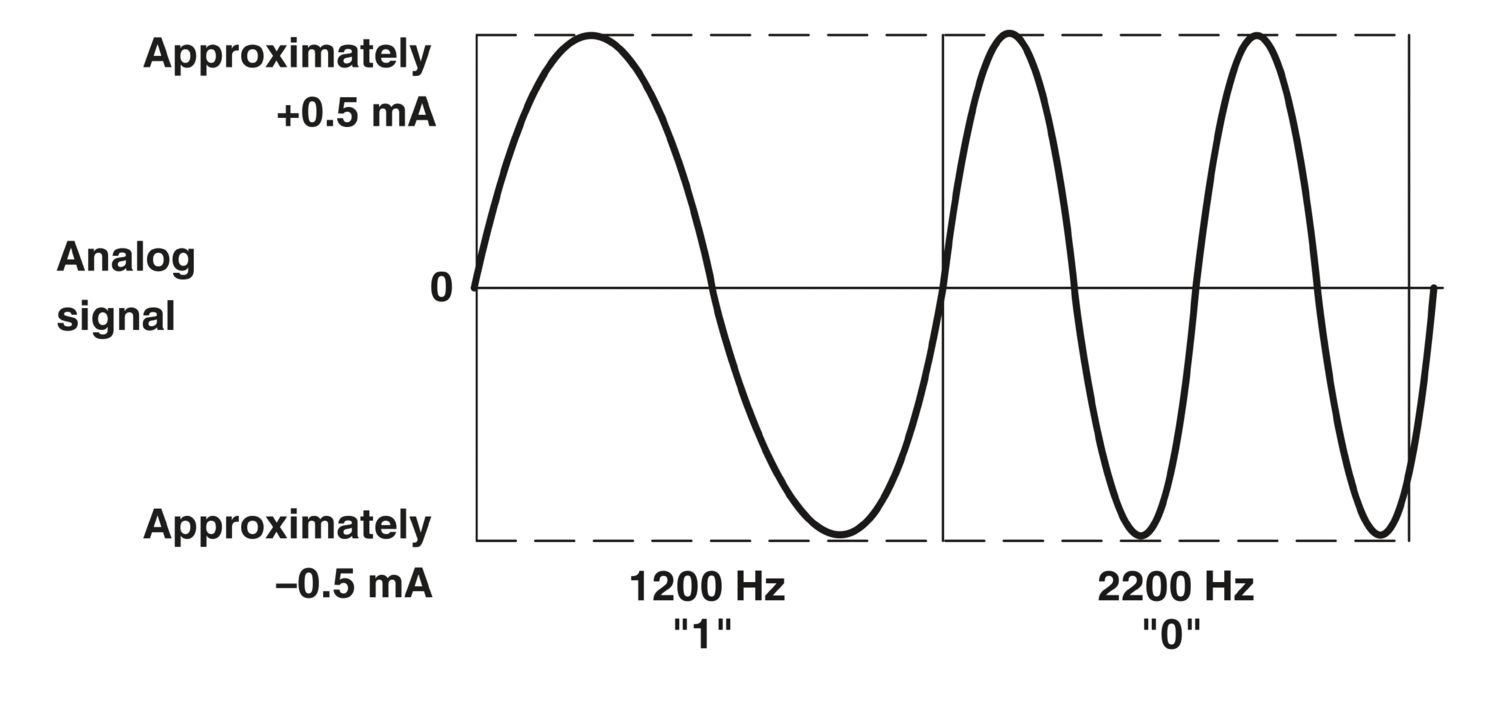
Bidirectional transmission of digital HART communication signals