
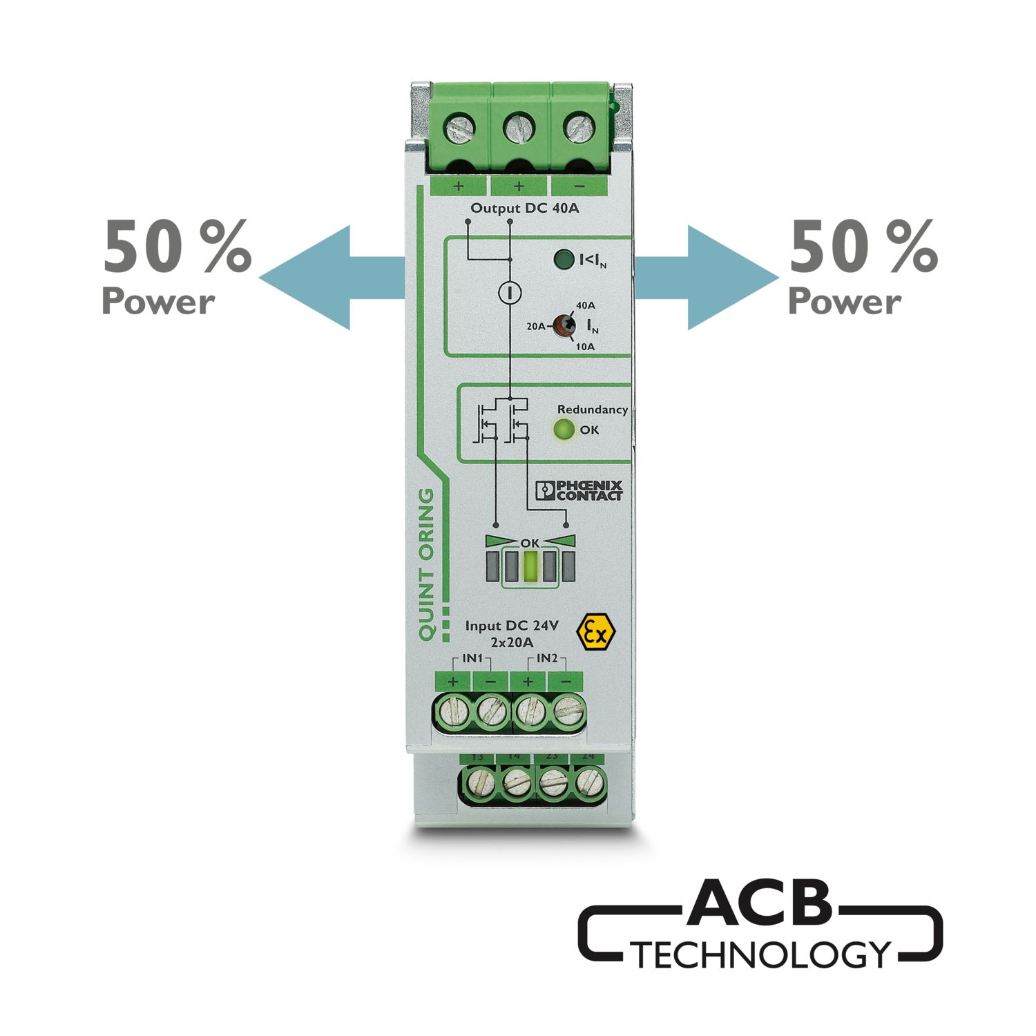
The Auto Current Balancing ACB technology of the QUINT ORING modules doubles the service life of redundantly operated power supplies by evenly utilizing the power supply units. The load current is automatically distributed symmetrically.
QUINT-ORING/24DC/2X10/1X20
-
Redundancy module, with protective coating
2320173
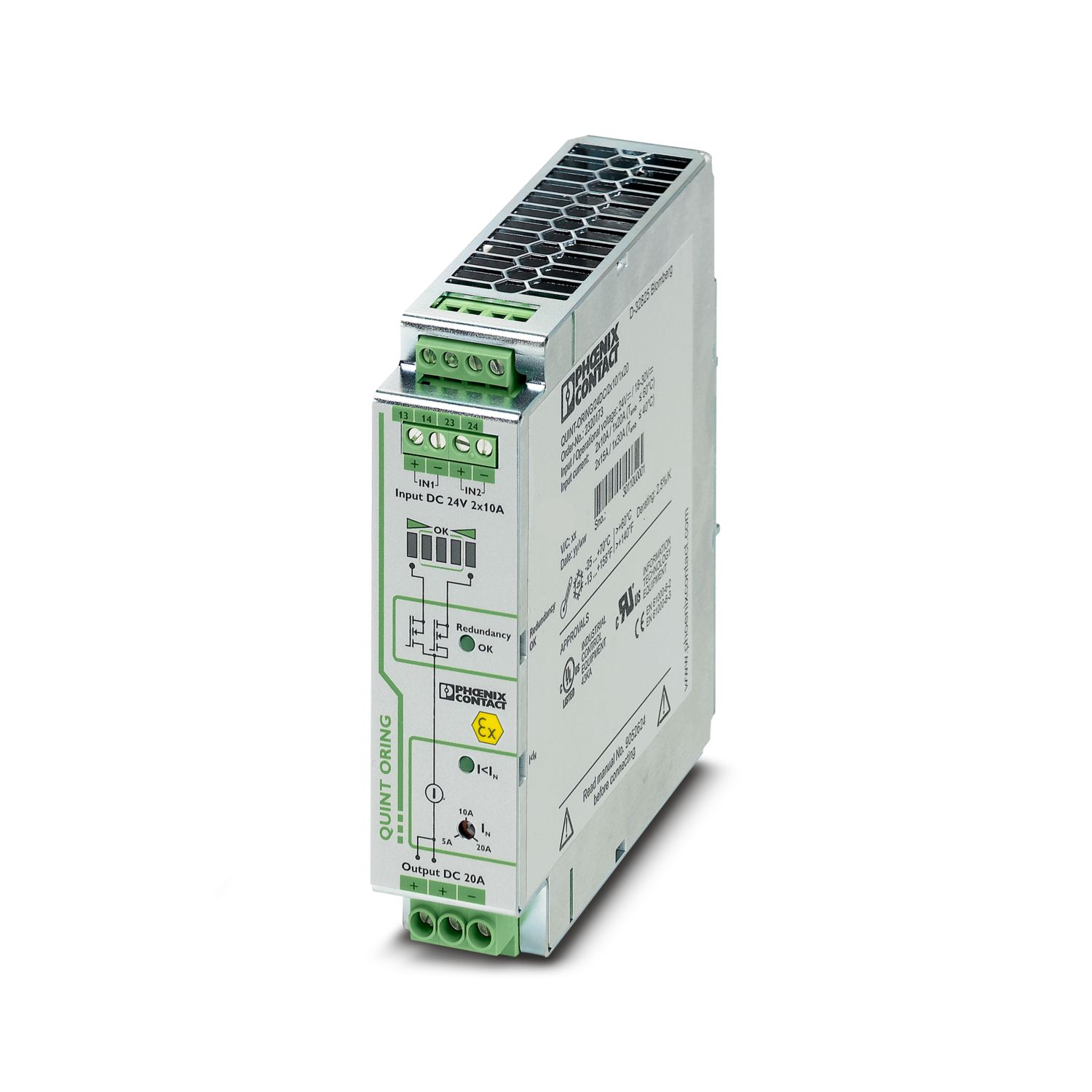
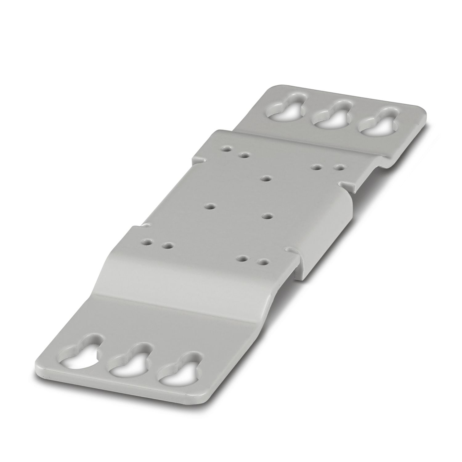
Active QUINT redundancy module for DIN rail mounting with Auto Current Balancing ACB technology and monitoring functions, input: 24 V DC, output: 24 V DC/2 x 10 A or 1 x 20 A, including mounted UTA 107/30 universal DIN rail adapter
Product details
UL Recognized
Approval ID: E211944UL Listed
Approval ID: E123528cUL Listed
Approval ID: E123528DNV
Approval ID: TAA000011FIECEE CB Scheme
Approval ID: DE/PTZ/0044NK
Approval ID: TA25015M| Nominal voltage UN | Nominal current IN | Cross section AWG | Cross section mm2 | |
|---|---|---|---|---|
| keine | ||||
| 500 V | 63 A | - 10 | ||
EAC
Approval ID: RU S-DE.BL08.W.00764ATEX
Approval ID: DEKRA_20ATEX0136_XIECEx
Approval ID: IECEx DEK 20.0082XCCC
Approval ID: 2024322303005876cUL Listed
Approval ID: E199827UL Listed
Approval ID: E199827INMETRO
Approval ID: DNV 22.0237 XNEPSI-EX
Approval ID: GYJ21.1003XEAC Ex
Approval ID: KZ 7500525010102095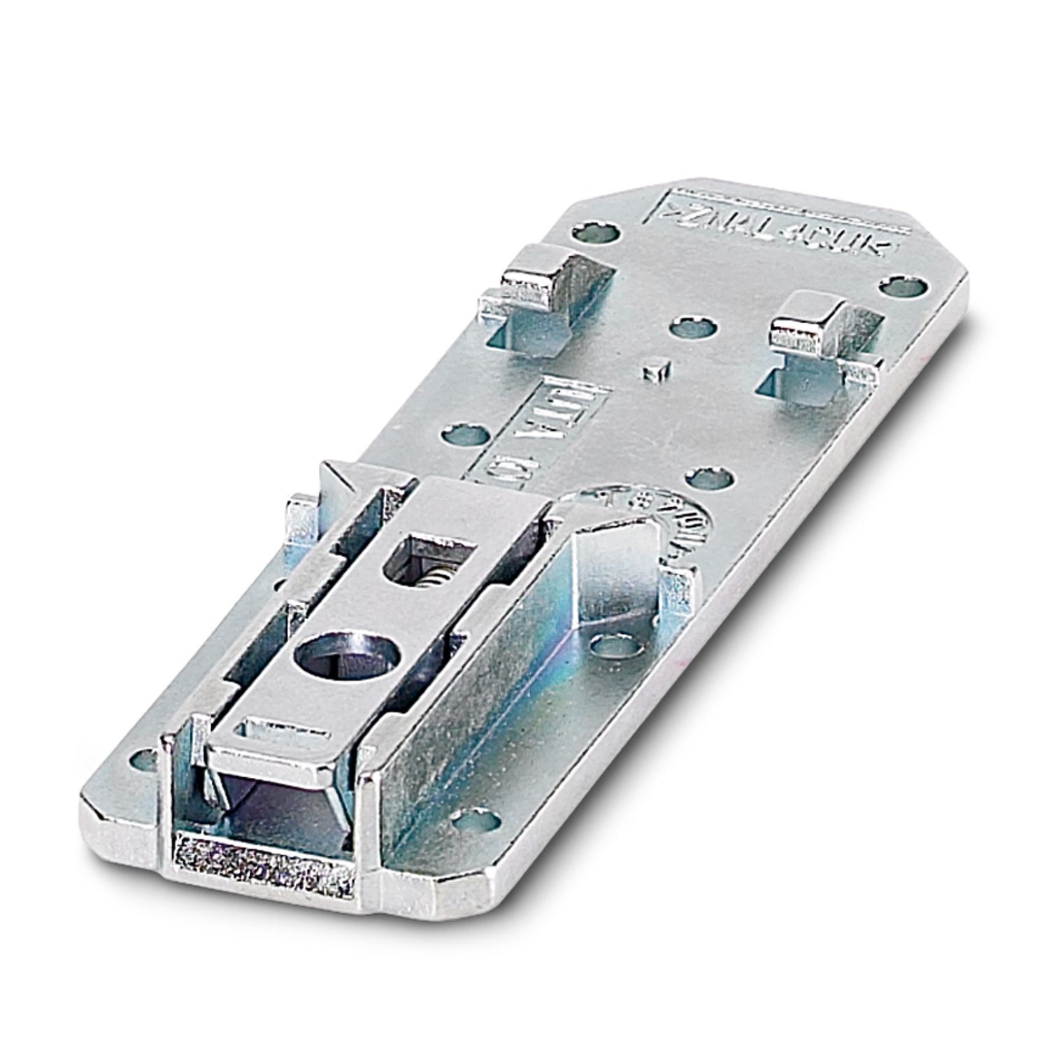
Your advantages
Service life of the redundant solution is doubled, thanks to uniform distribution of the load
Save energy
Permanent monitoring of redundancy
Consistent redundancy up to the load
Frequently asked questions
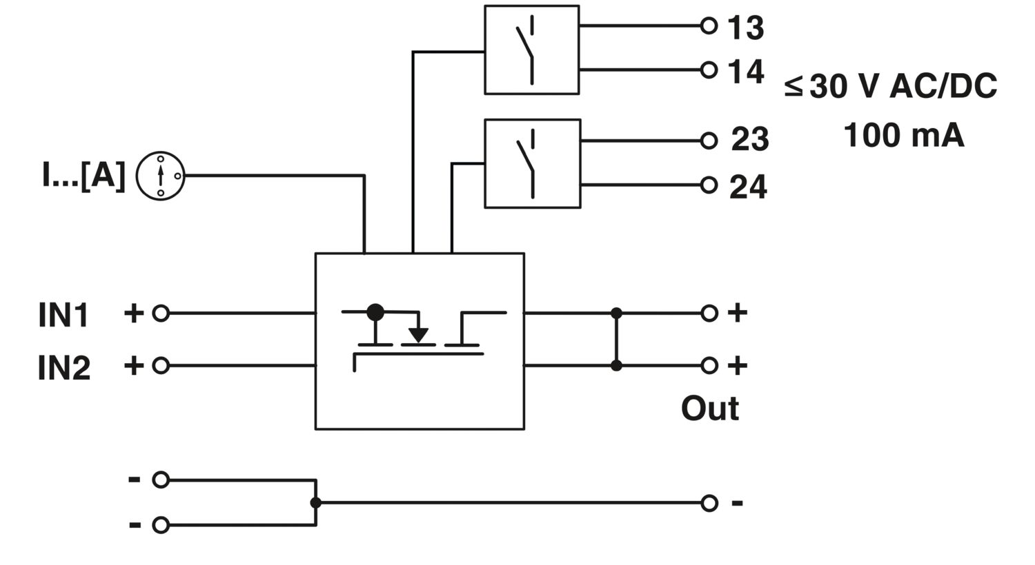
Is there a signal if there is a cable break on the output side or if a cable is not connected?
No. The QUINT4-ORING/12-24DC/2X10/2X10 is recommended as an alternative for signaling this.
https://www.phoenixcontact.com/en-us/products/power-supply-quint4-ps1ac24dc5-2904600
Does the item have integrated surge protection?
Yes, the item has surge protection for voltages from 32 V. To protect the load from hazardous voltage, the respective input is switched off in the event of surge voltage. This means that the load can be supplied safely via the redundant power supply.... View more
Yes, the item has surge protection for voltages from 32 V. To protect the load from hazardous voltage, the respective input is switched off in the event of surge voltage. This means that the load can be supplied safely via the redundant power supply. The fault is signaled via the "Red OK" relay (13/14) and the LED.
View lessWhat is "ACB"?
"ACB" stands for "Auto Current Balancing". Small differences in the output voltage of parallel power supplies have a large influence on the current supplied by a power supply. This technology balances out the current up to a voltage difference of 0.3... View more
"ACB" stands for "Auto Current Balancing". Small differences in the output voltage of parallel power supplies have a large influence on the current supplied by a power supply. This technology balances out the current up to a voltage difference of 0.3 V. Thanks to the balanced utilization and the lower load on an individual power supply, the service life of the redundant system can be doubled.
View less