
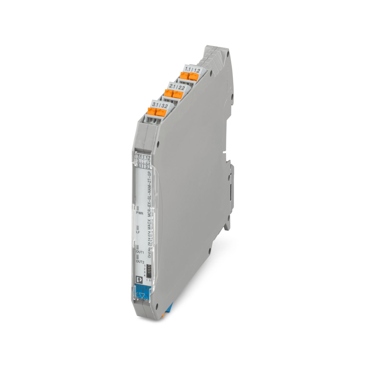
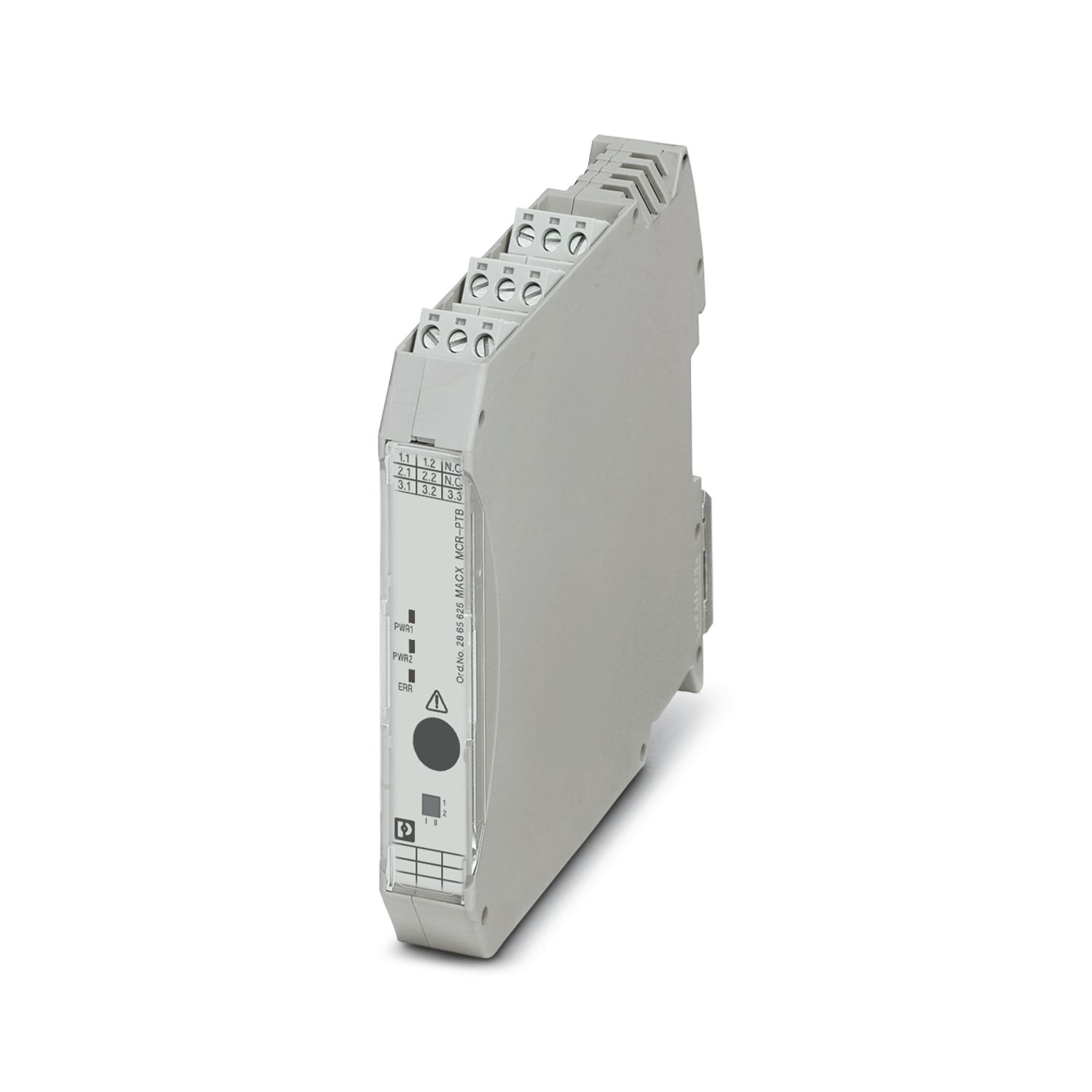
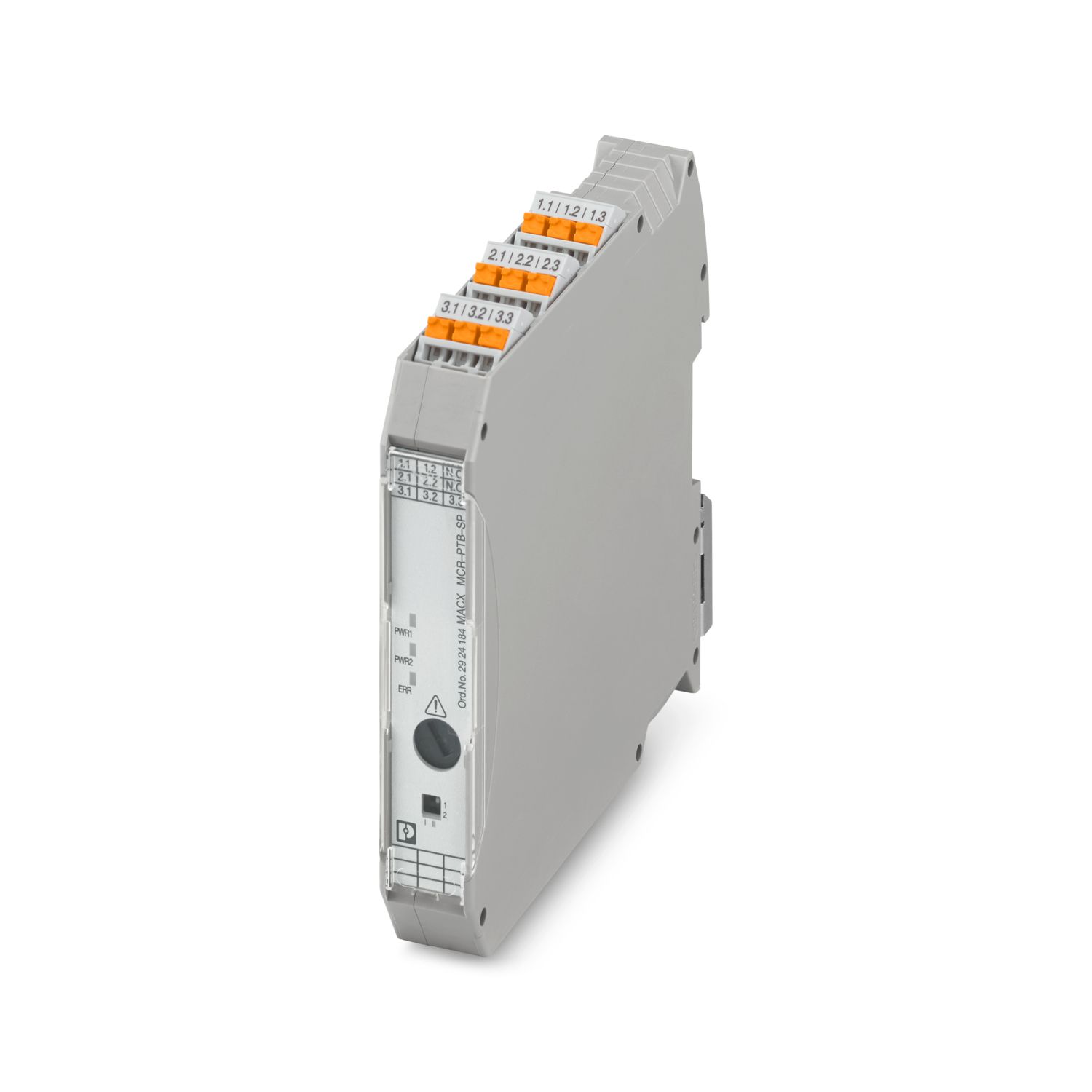
MACX MCR-EX-SL-NAM-2T-SP
-
Isolation switch amplifier
2924074
Free download available.
Downloads
Product details
| Product family | MACX Analog |
| Application | Digital IN |
| No. of channels | 1 |
| Configuration | DIP switches |
| Functionality | |
| Configuration | DIP switches |
| Electrical isolation | 3-way isolation |
| Electrical isolation between input and output | yes |
| Line monitoring | Line fault detection |
| Electrical isolation | |
| Overvoltage category | II |
| Pollution degree | 2 |
| Electrical isolation Input/output IEC/EN 60079-11 | |
| Standards/regulations | IEC/EN 60079-11 |
| Rated insulation voltage | 375 VPP |
| Electrical isolation Input/supply, DIN rail connector IEC/EN 60079-11 | |
| Standards/regulations | IEC/EN 60079-11 |
| Rated insulation voltage | 375 VPP |
| Electrical isolation Input/output/supply, DIN rail connector IEC/EN 61010-1 | |
| Standards/regulations | IEC/EN 61010-1 |
| Rated insulation voltage | 300 Vrms |
| Test voltage | 2.5 kV AC (50 Hz, 60 s) |
| Insulation | Safe isolation |
| Electrical isolation Output 1/output 2 IEC/EN 61010-1 | |
| Standards/regulations | IEC/EN 61010-1 |
| Rated insulation voltage | 50 Vrms |
| Test voltage | 1 kV AC (50 Hz, 60 s) |
| Insulation | Basic insulation |
| Supply | |
| Nominal supply voltage | 24 V DC -20 % ... +25 % |
| Supply voltage range | 19.2 V DC ... 30 V DC |
| Max. current consumption | < 28 mA (24 V DC) |
| Power dissipation | ≤ 800 mW |
| Power consumption | ≤ 800 mW |
| Signal: NAMUR | |
| Description of the input | intrinsically safe |
| Number of inputs | 1 |
| Available input sources | NAMUR proximity sensors (IEC/EN 60947-5-6) |
| floating switch contacts | |
| Switch contacts with resistance circuit | |
| Switching threshold "0" signal current | < 1.2 mA (blocking) |
| Switching threshold "1" signal, current | > 2.1 mA (conductive) |
| Short-circuit current | 8 mA |
| Switching hysteresis | < 0.2 mA |
| Line fault detection | < 0.05 mA ... 0.35 mA (Line break) |
| < 100 Ω ... 360 Ω (Short circuit) | |
| Activated /deactivated via DIP switch | |
| Open-circuit voltage | 8 V DC |
| Switching: Transistor | |
| Output description | passive |
| Minimum switching voltage | 3 V DC |
| Maximum switching voltage | 30 V DC |
| Drop (ΔU) | < 1.4 V |
| Max. switching current | 50 mA (short-circuit-proof) |
| Min. switching current | 5 mA (short-circuit-proof) |
| Switching frequency | ≤ 5 kHz |
| Signal | |
| Number of outputs | 2 |
| Connection method | Push-in connection |
| Stripping length | 10 mm |
| Conductor cross-section rigid | 0.2 mm² ... 2.5 mm² |
| Conductor cross-section flexible | 0.2 mm² ... 2.5 mm² |
| Conductor cross-section flexible (2 conductors with same cross section) | 0.25 mm² ... 0.34 mm² (TWIN ferrule without plastic sleeve) |
| 0.5 mm² ... 1.5 mm² (TWIN ferrule with plastic sleeve) | |
| Conductor cross-section AWG | 24 ... 14 |
| 24 ... 22 (TWIN ferrule without plastic sleeve) | |
| 20 ... 16 (TWIN ferrule with plastic sleeve) |
| Ex installation (EPL) | Gc |
| Div. 2 | |
| Ex i circuits (EPL) | Ga |
| Da | |
| Ma | |
| Div. 1 | |
| Safety data | |
| Max. internal inductance Li | negligible |
| Max. internal capacitance Ci | 1.1 nF |
| Max. output voltage Uo | 9.6 V |
| Max. output current Io | 10 mA |
| Max. output power Po | 25 mW |
| Safety-related maximum voltage Um | 253 V AC |
| 125 V DC | |
| IIC (simple circuit): Max. external inductivity Lo / Max. external capacitance Co | 300 mH / 3.6 µF |
| IIB/IIIC (simple circuit): Max. external inductivity Lo / Max. external capacitance Co | 1000 mH / 26 µF |
| IIA (simple circuit): Max. external inductivity Lo / Max. external capacitance Co | 1000 mH / 210 µF |
| IIC (mixed circuit): Max. external inductivity Lo / Max. external capacitance Co | 100 mH / 510 nF, 50 mH / 580 nF, 5 mH / 600 nF |
| IIB/IIA/IIIC (mixed circuit): Max. external inductivity Lo / Max. external capacitance Co | 100 mH / 1 µF |
| Data | |
| No. of channels | 0 |
| Status display | Green LED (supply voltage) |
| LED yellow (switching state) | |
| Red LED (line errors) |
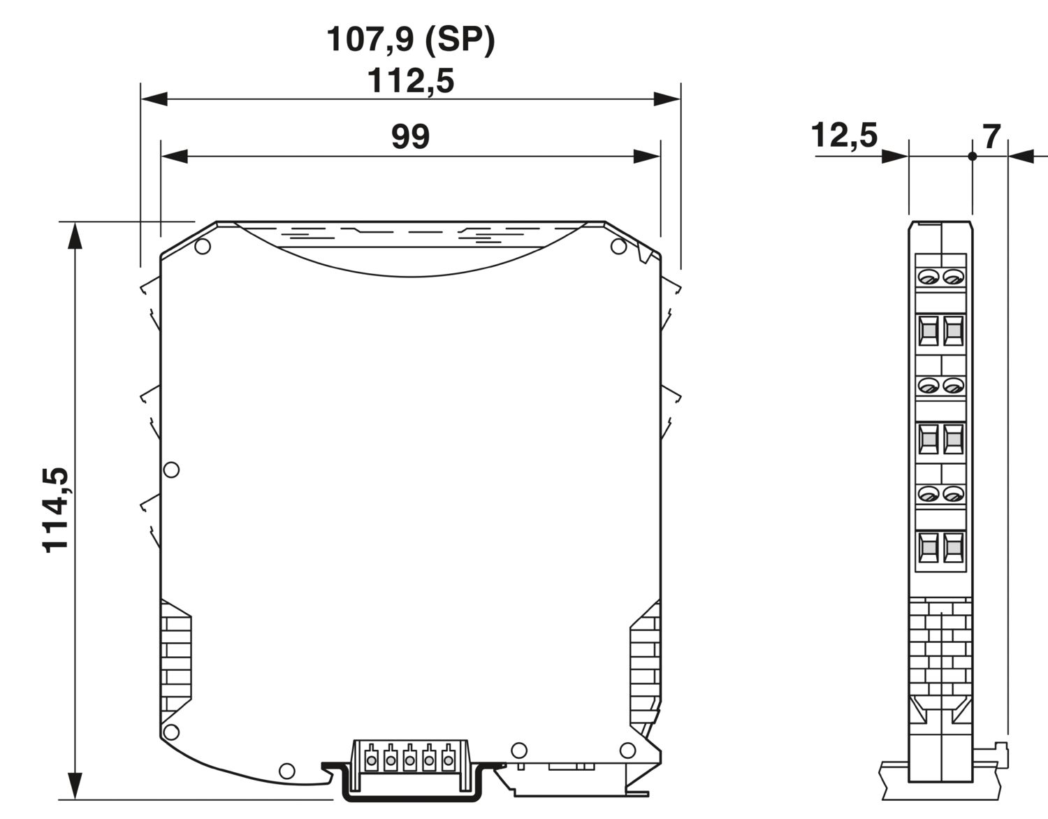
| Dimensional drawing |
|
| Width | 12.5 mm |
| Height | 107.9 mm |
| Depth | 113.7 mm |
| Depth NS 35/7,5 | 114.5 mm (Snapped onto DIN rail NS 35/7,5 in accordance with EN 60715) |
| Color | gray (RAL 7042) |
| Flammability rating according to UL 94 (Housing) | V0 (Housing) |
| Housing material | PA 6.6-FR |
| Safety data | |
| Safety Integrity Level (SIL) | 2 |
| Safety data | |
| Safety Integrity Level (SIL) | 2 |
| Ambient conditions | |
| Degree of protection | IP20 (not assessed by UL) |
| Ambient temperature (operation) | -40 °C ... 60 °C (Any mounting position) |
| -40 °C ... 70 °C (Derating) | |
| Ambient temperature (storage/transport) | -40 °C ... 80 °C |
| Permissible humidity (operation) | 10 % ... 95 % (non-condensing) |
| Altitude range (≤ 2000 m) | |
| Altitude | ≤ 2000 m (The technical data refers to altitudes ≤2000 m above mean sea level. For altitudes >2000 m above mean sea level, refer to the data sheet.) |
| Ambient temperature (operation) | -40 °C ... 60 °C |
| -40 °C ... 70 °C (Derating) | |
| Rated insulation voltage | 265 V AC/DC (UIsolation “ec”: Supply, input / output) |
| Altitude range (≤ 3000 m) | |
| Height range | > 2000 m ... 3000 m |
| Ambient temperature (operation) | -40 °C ... 54 °C |
| -40 °C ... 63 °C (Derating) | |
| Safety-related maximum voltage Um | 190 V AC |
| 110 V DC | |
| Rated insulation voltage | 190 V AC/DC (UIsolation “ec”: Supply, input / output) |
| Altitude range (≤ 4000 m) | |
| Height range | > 3000 m ... 4000 m |
| Ambient temperature (operation) | -40 °C ... 48 °C |
| -40 °C ... 56 °C (Derating) | |
| Safety-related maximum voltage Um | 60 V |
| Rated insulation voltage | 60 V AC/DC (UIsolation “ec”: Supply, input / output) |
| Altitude range (≤ 5000 m) | |
| Height range | > 4000 m ... 5000 m |
| Ambient temperature (operation) | -40 °C ... 42 °C |
| -40 °C ... 49 °C (Derating) | |
| Safety-related maximum voltage Um | 60 V |
| Rated insulation voltage | 60 V AC/DC (UIsolation “ec”: Supply, input / output) |
| CE | |
| Certificate | CE-compliant |
| Note | and EN 61326 |
| ATEX | |
| Identification | II (1) G [Ex ia Ga] IIC |
| II (1) D [Ex ia Da] IIIC | |
| II 3(1) G Ex ec [ia Ga] IIC T4 Gc | |
| I (M1) [Ex ia Ma] I | |
| Certificate | IBExU 08 ATEX 1100 X |
| IECEx | |
| Identification | [Ex ia Ga] IIC |
| [Ex ia Da] IIIC | |
| Ex ec [ia Ga] IIC T4 Gc | |
| [Ex ia Ma] I | |
| Certificate | IECEx IBE 08.0005X |
| CCC / China-Ex | |
| Identification | [Ex ia Ga] IIC |
| [Ex ia Da] IIIC | |
| Ex ec [ia Ga] IIC T4 Gc | |
| Certificate | 2022122316115977 |
| UL, USA/Canada | |
| Identification | Class I Div 2; IS for Class I, II, III Div 1 |
| Certificate | , C.D.-No 83104549 |
| Shipbuilding approval | |
| Certificate | DNV GL TAA00000AG |
| Safety Integrity Level (SIL, IEC 61508) | |
| Identification | 2 |
| Certificate | IN-AT-AS-MRL-25-00008 |
| Systematic Capability | |
| Identification | 3 |
| INMETRO | |
| Identification | [Ex ia Ga] IIC |
| [Ex ia Da] IIIC | |
| Ex ec [ia Ga] IIC T4 Gc | |
| [Ex ia Ma] I | |
| Certificate | DNV 18.0141 X |
| Shipbuilding data | |
| Temperature | B |
| Humidity | B |
| Vibration | A |
| EMC | B |
| Enclosure | Required protection according to the Rules shall be provided upon installation on board |
| Electromagnetic compatibility | Conformance with EMC directive |
| Noise immunity | EN 61000-6-2 |
| Noise emission | |
| Standards/regulations | EN 61000-6-4 |
| Electromagnetic HF field | |
| Designation | Electromagnetic RF field |
| Standards/regulations | EN 61000-4-3 |
| Evaluation criterion | A |
| Fast transients (burst) | |
| Designation | Fast transients (burst) |
| Standards/regulations | EN 61000-4-4 |
| Evaluation criterion | A |
| Conducted interference | |
| Designation | Conducted interferences |
| Standards/regulations | EN 61000-4-6 |
| Evaluation criterion | A |
| Electrical isolation | 3-way isolation |
| GB Standard | |
| Standards/regulations | GB/T 3836.1 |
| GB/T 3836.3 | |
| GB/T 3836.4 | |
| Mounting type | DIN rail mounting |


Your advantages
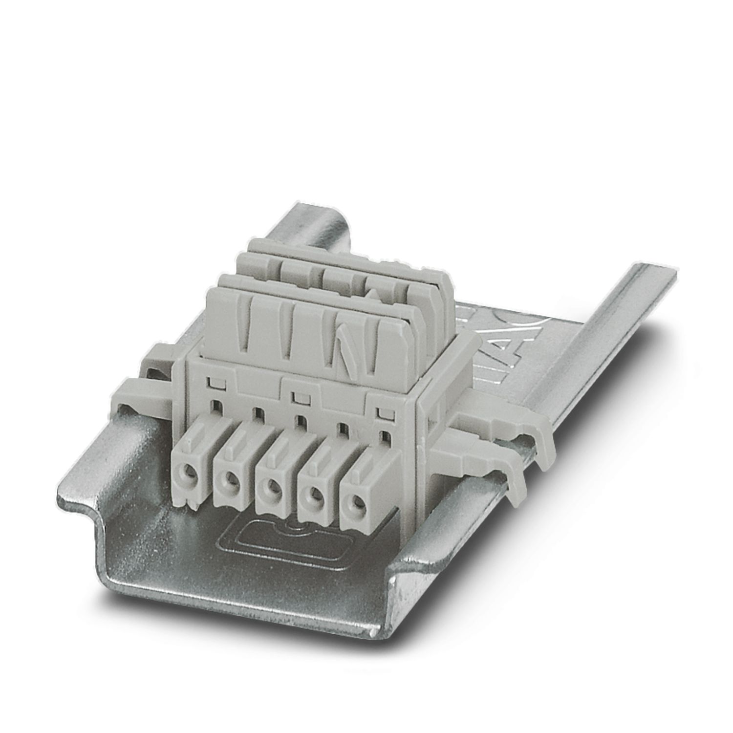
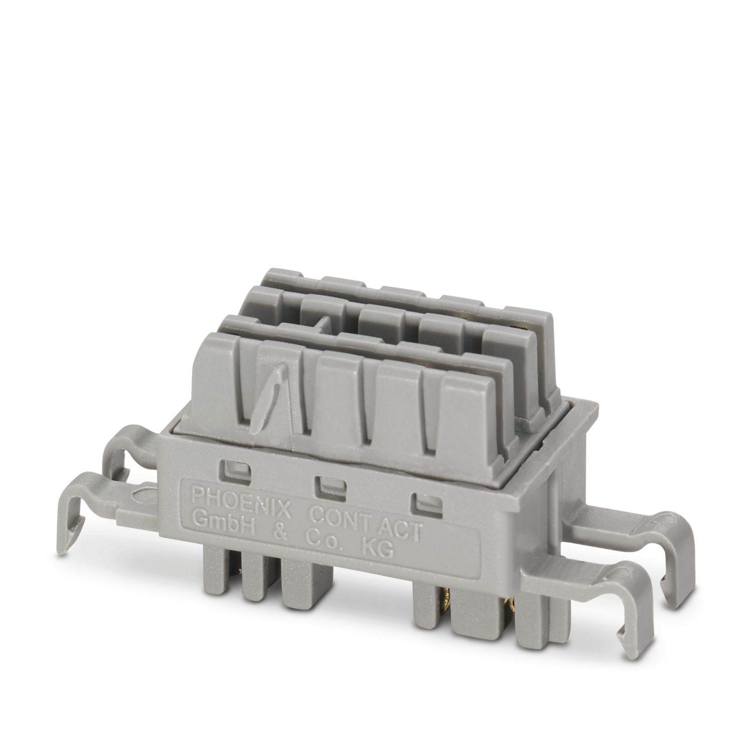
Power supply and error indication possible via DIN rail connector
Up to SIL 2 in accordance with EN 61508
Installation in zone 2, protection type "n" (EN 60079-15) permitted
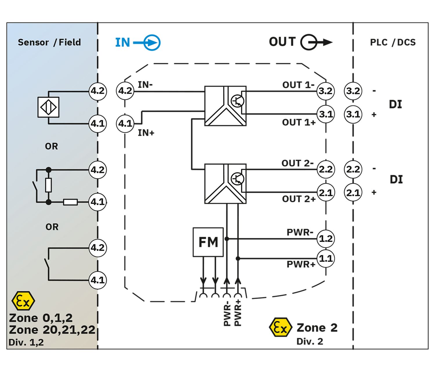
Signal output 2 can also be used as an error signaling output
Line fault detection (LFD), can be activated/deactivated, error indicated by flashing red LED with disabling of transistor output
Direction of operation can be selected (operating or closed circuit current behavior)
2 transistor signal outputs (passive); up to 5 kHz
4-way electrical isolation
Input for NAMUR proximity sensors (EN 60947-5-6), floating contacts or contacts with resistance circuit, [Ex ia] IIC
LED indicators for supply voltage, switching state, and malfunction in accordance with NAMUR NE 44